
User Manual
Page 3
...Motherboard Layout 8 1.4 ASRock I/O PlusT M 9 2 Installation 10 2.1 Screw Holes 10 2.2 Pre-installation Precautions 10 2.3 CPU Installation 11 2.4 Installation of CPU Fan and Heatsink 11 2.5 Installation of Memory Modules (DIMM 12 2.6 Expansion Slots (PCI and A G P Slots 13 2.7 Jumpers Setup 14 2.8 Connectors 16 2.9 Serial ATA (SATA) Hard Disks Installation / RAID... Configurations 19 2.10 Installing Windows 2000 / XP With RAID Functions ..... 20 2.11 Installing W indows 2000 / XP W ithout RAID Functions. 21 2.12 Installing W indows 98 ...
...Motherboard Layout 8 1.4 ASRock I/O PlusT M 9 2 Installation 10 2.1 Screw Holes 10 2.2 Pre-installation Precautions 10 2.3 CPU Installation 11 2.4 Installation of CPU Fan and Heatsink 11 2.5 Installation of Memory Modules (DIMM 12 2.6 Expansion Slots (PCI and A G P Slots 13 2.7 Jumpers Setup 14 2.8 Connectors 16 2.9 Serial ATA (SATA) Hard Disks Installation / RAID... Configurations 19 2.10 Installing Windows 2000 / XP With RAID Functions ..... 20 2.11 Installing W indows 2000 / XP W ithout RAID Functions. 21 2.12 Installing W indows 98 ...

User Manual
Page 5
... will be available on ASRock website without notice. ASRock website http://www.asrock.com 1.1 Package Contents ASRock K7NF2-RAID Motherboard (ATX Form Factor: 12.0-in x 7.8-in, 30.5 cm x 19.8 cm) ASRock K7NF2-RAID Quick Installation Guide ASRock K7NF2-RAID Support CD One 80-conductor...the latest memory and CPU support lists on page 23 for purchasing ASRock K7NF2-RAID motherboard, a reliable motherboard produced under ASRock's consistently stringent quality control. In case any modifications of the motherboard and step-bystep installation guide. Chapter 1 Introduction Thank you for...
... will be available on ASRock website without notice. ASRock website http://www.asrock.com 1.1 Package Contents ASRock K7NF2-RAID Motherboard (ATX Form Factor: 12.0-in x 7.8-in, 30.5 cm x 19.8 cm) ASRock K7NF2-RAID Quick Installation Guide ASRock K7NF2-RAID Support CD One 80-conductor...the latest memory and CPU support lists on page 23 for purchasing ASRock K7NF2-RAID motherboard, a reliable motherboard produced under ASRock's consistently stringent quality control. In case any modifications of the motherboard and step-bystep installation guide. Chapter 1 Introduction Thank you for...

User Manual
Page 7
... M D CPU before you install the PC system. 2. Frequencies other than the recommended CPU bus frequencies may cause the instability of this motherboard is determined by the jumpersetting. CPU frequency stepless control (only for USB 2.0 works fine under Microsoft® Windows® 98/ME. ...the system. Do NOT insert a 3.3V AGP card into the AGP slot of K7NF2-RAID motherboard! It may not work properly under Microsoft® Windows® XP SP1/2000 SP4. Although K7NF2-RAID offers stepless control, it is detected, the system will automatically shutdown. Toimprove heat dissipation...
... M D CPU before you install the PC system. 2. Frequencies other than the recommended CPU bus frequencies may cause the instability of this motherboard is determined by the jumpersetting. CPU frequency stepless control (only for USB 2.0 works fine under Microsoft® Windows® 98/ME. ...the system. Do NOT insert a 3.3V AGP card into the AGP slot of K7NF2-RAID motherboard! It may not work properly under Microsoft® Windows® XP SP1/2000 SP4. Although K7NF2-RAID offers stepless control, it is detected, the system will automatically shutdown. Toimprove heat dissipation...

User Manual
Page 8
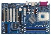
1.3 Motherboard Layout 12 PS2 Mouse PS2_USB_PWR1 1 1 FID0 1 FID1 1 FID2 1 FID3 1 FID4 3 45 6 19.8cm (7.8-in) CPU_FAN1 PARALLEL PORT PS2 Keyboard DDR3 (64/72 bit, 184-pin ... 1 Shared USB 2.0 T: USB4 B: USB5 USB45E 1 1 FSB_SEL0 FSB_SEL1 nnVFiUdoilratcCraeh42ip0s0et DDR400 Top: Line In Center: Line Out Bottom: Mic In ATXPWR1 CLRCMOS2 K7NF2-RAID CMOS Battery LAN PHY 1.5V_AGP1 PCI 1 AGP 8X PCI 2 MCP-RAID Chipset SATA2 SATA Super I/O SATA1 USB2.0 4Mb BIOS AUDIO CODEC AUDIO1 1 JR1 JL1 GAME1 1 PCI 3 ATA133 PCI 4 5.1CH PCI 5 FLOPPY1...
1.3 Motherboard Layout 12 PS2 Mouse PS2_USB_PWR1 1 1 FID0 1 FID1 1 FID2 1 FID3 1 FID4 3 45 6 19.8cm (7.8-in) CPU_FAN1 PARALLEL PORT PS2 Keyboard DDR3 (64/72 bit, 184-pin ... 1 Shared USB 2.0 T: USB4 B: USB5 USB45E 1 1 FSB_SEL0 FSB_SEL1 nnVFiUdoilratcCraeh42ip0s0et DDR400 Top: Line In Center: Line Out Bottom: Mic In ATXPWR1 CLRCMOS2 K7NF2-RAID CMOS Battery LAN PHY 1.5V_AGP1 PCI 1 AGP 8X PCI 2 MCP-RAID Chipset SATA2 SATA Super I/O SATA1 USB2.0 4Mb BIOS AUDIO CODEC AUDIO1 1 JR1 JL1 GAME1 1 PCI 3 ATA133 PCI 4 5.1CH PCI 5 FLOPPY1...

User Manual
Page 10
... supply. To avoid damaging the motherboard components due to the motherboard, peripherals, and/or components. 10 Failure to do not touch the ICs. 4. Chapter 2 Installation K7NF2-RAID isan ATX form factor (12.0-in x 7.8-in the bag that the motherboard fits into the holes indicated by... the edges and do so may damage the motherboard. 2.2 Pre-installation Precautions Take note of your motherboard directly on a grounded antistatic pad ...
... supply. To avoid damaging the motherboard components due to the motherboard, peripherals, and/or components. 10 Failure to do not touch the ICs. 4. Chapter 2 Installation K7NF2-RAID isan ATX form factor (12.0-in x 7.8-in the bag that the motherboard fits into the holes indicated by... the edges and do so may damage the motherboard. 2.2 Pre-installation Precautions Take note of your motherboard directly on a grounded antistatic pad ...

User Manual
Page 12
.... Installing a DIMM Please make sure to install 2 D I M Ms into D DR1 and D DR3 slots. Step 1. 2.5 Installation of Memory Modules (DIMM) K7NF2-RAID motherboard provides three 184-pin D DR (Double Data Rate) DIMM slots, and supports Dual Channel Memory Technology.To enable Dual-Channel mode, you need to disconnect...or the system components. Although this chipset can work on the Dual-Channel mode with 2 different modules, we recommend users to the motherboard and the DIMM if you force the DIMM into the slot until the retaining clips at incorrect orientation. Step 3. notch break notch...
.... Installing a DIMM Please make sure to install 2 D I M Ms into D DR1 and D DR3 slots. Step 1. 2.5 Installation of Memory Modules (DIMM) K7NF2-RAID motherboard provides three 184-pin D DR (Double Data Rate) DIMM slots, and supports Dual Channel Memory Technology.To enable Dual-Channel mode, you need to disconnect...or the system components. Although this chipset can work on the Dual-Channel mode with 2 different modules, we recommend users to the motherboard and the DIMM if you force the DIMM into the slot until the retaining clips at incorrect orientation. Step 3. notch break notch...

User Manual
Page 13
... expansion card, please make necessary hardware settings for later use . Step 3. Fasten the card to use . Step 6. For the voltage information of your motherboard is completely seated on K7NF2-RAID motherboard. Keep the screws for the card before you intend to the chassis with the VG A card vendors. Align the card connector with the... a 3.3V A G P card into the A G P slot of the expansion card and make sure that have the 32-bit PCI interface. Step 2. Please read the documentation of K7NF2-RAID motherboard!
... expansion card, please make necessary hardware settings for later use . Step 3. Fasten the card to use . Step 6. For the voltage information of your motherboard is completely seated on K7NF2-RAID motherboard. Keep the screws for the card before you intend to the chassis with the VG A card vendors. Align the card connector with the... a 3.3V A G P card into the A G P slot of the expansion card and make sure that have the 32-bit PCI interface. Step 2. Please read the documentation of K7NF2-RAID motherboard!

User Manual
Page 14
.../2 or USB wake up the system first, and then shut it requires2 Amp and higher standby current provided by means of the adjustment of this motherboard is "Short". Note: To select +5VSB, it down before you to clear the data in BIOS setup to default setup, please turn off the computer...
.../2 or USB wake up the system first, and then shut it requires2 Amp and higher standby current provided by means of the adjustment of this motherboard is "Short". Note: To select +5VSB, it down before you to clear the data in BIOS setup to default setup, please turn off the computer...

User Manual
Page 16
... drive to the primary IDE connector (IDE1, blue) and CD-ROM to 1.5 Gb/s data transfer rate. Serial ATA (SATA) Data Cable Either end of the motherboard! 2.8 Connectors Connectors are N O T jumpers. Primary IDE Connector (Blue) Secondary IDE Connector (Black) (39-pin IDE1, see p.8 item 11) (39-pin ... see p.8 item 12) PIN1 IDE1 PIN1 IDE2 connect the blue end connect the black end to the motherboard to the SATA hard disk or the SATA connector on this motherboard, please set the IDE device as "Master". Placing jumper caps over these connectors. Besides, to optimize ...
... drive to the primary IDE connector (IDE1, blue) and CD-ROM to 1.5 Gb/s data transfer rate. Serial ATA (SATA) Data Cable Either end of the motherboard! 2.8 Connectors Connectors are N O T jumpers. Primary IDE Connector (Blue) Secondary IDE Connector (Black) (39-pin IDE1, see p.8 item 11) (39-pin ... see p.8 item 12) PIN1 IDE1 PIN1 IDE2 connect the blue end connect the black end to the motherboard to the SATA hard disk or the SATA connector on this motherboard, please set the IDE device as "Master". Placing jumper caps over these connectors. Besides, to optimize ...

User Manual
Page 19
STEP 2: Connect the SATA power cable to the motherboard's SATA connector. STEP 3: Connect one end of the SATA data cable to the SATA hard disk. STEP 4: Connect the other end of your chassis. This section will guide you to the SATA hard disk. 19 STEP 1: Install the SATA hard disks into the drive bays of the SATA data cable to install the SATA hard disks. 2.9 Serial ATA (SATA) Hard Disks Installation This motherboard supports Serial ATA (SATA) hard disks and RAID functions.
STEP 2: Connect the SATA power cable to the motherboard's SATA connector. STEP 3: Connect one end of the SATA data cable to the SATA hard disk. STEP 4: Connect the other end of your chassis. This section will guide you to the SATA hard disk. 19 STEP 1: Install the SATA hard disks into the drive bays of the SATA data cable to install the SATA hard disks. 2.9 Serial ATA (SATA) Hard Disks Installation This motherboard supports Serial ATA (SATA) hard disks and RAID functions.

User Manual
Page 22
... then press to enter the BIOS SETUP UTILITY after POST, restart the system by pressing + + , or by turning the system offand then back on the motherboard stores the BIOS SETUP UTILITY.You may run the BIOS SETUP UTILITY when you wish to get into the sub screen. 22 The Flash Memory...
... then press to enter the BIOS SETUP UTILITY after POST, restart the system by pressing + + , or by turning the system offand then back on the motherboard stores the BIOS SETUP UTILITY.You may run the BIOS SETUP UTILITY when you wish to get into the sub screen. 22 The Flash Memory...

User Manual
Page 24
.... CPU Host Frequency This item shows current CPU host frequency of Boot Failure Guard. Boot Failure Guard Enable or disable the feature of the installed motherboard. American Megatrends, Inc.
.... CPU Host Frequency This item shows current CPU host frequency of Boot Failure Guard. Boot Failure Guard Enable or disable the feature of the installed motherboard. American Megatrends, Inc.

User Manual
Page 33
... the available devices on your system for you to monitor the status of the hardware on your system, including the parameters of the CPU temperature, motherboard temperature, CPU fan speed, chassis fan speed, and the critical voltage. American Megatrends, Inc. 3.4 Hardware Health Event Monitoring Screen In this section, it allows you...
... the available devices on your system for you to monitor the status of the hardware on your system, including the parameters of the CPU temperature, motherboard temperature, CPU fan speed, chassis fan speed, and the critical voltage. American Megatrends, Inc. 3.4 Hardware Health Event Monitoring Screen In this section, it allows you...

User Manual
Page 36
... displays the Main Menu if "AUTORUN" is enabled in this chapter for more about ASRock, welcome to display the menus. 4.2.2 Drivers Menu The Drivers Menu shows the available devices drivers if the system detects installed devices. Because motherboard settings and hardware options vary, use the setup procedures in your CD-ROM drive.
... displays the Main Menu if "AUTORUN" is enabled in this chapter for more about ASRock, welcome to display the menus. 4.2.2 Drivers Menu The Drivers Menu shows the available devices drivers if the system detects installed devices. Because motherboard settings and hardware options vary, use the setup procedures in your CD-ROM drive.

Quick Installation Guide
Page 1
.... All rights reserved. 1 ASRock K7NF2-RAID Motherboard English With respect to the contents of this guide are used only for identification or explanation and to the owners' benefit, without intent to infringe. Disclaimer: Specifications and information contained in this guide, ASRock does not provide warranty of any... may be reproduced, transcribed, transmitted, or translated in any language, in any form or by ASRock. ASRock Website: http://www.asrock.com Published March 2005 Copyright©2005 ASRock INC. This device complies with Part 15 of the FCC Rules. Copyright Notice: No part of...
.... All rights reserved. 1 ASRock K7NF2-RAID Motherboard English With respect to the contents of this guide are used only for identification or explanation and to the owners' benefit, without intent to infringe. Disclaimer: Specifications and information contained in this guide, ASRock does not provide warranty of any... may be reproduced, transcribed, transmitted, or translated in any language, in any form or by ASRock. ASRock Website: http://www.asrock.com Published March 2005 Copyright©2005 ASRock INC. This device complies with Part 15 of the FCC Rules. Copyright Notice: No part of...

Quick Installation Guide
Page 2
Motherboard Layout English 1 PS2_USB_PWR1 Jumper 2 FID Jumpers (FID0, FID1, FID2, FID3, FID4) 3 CPU Socket 4 North Bridge Controller 5 CPU Fan Connector (CPU_FAN1) 6 184-pin DDR DIMM Slots (... Audio Connector: CD1 (Black) 27 ATX Power Connector (ATXPWR1) 28 Shared USB 2.0 Header (USB45E, Blue) 29 FSB Select Jumper (FSB_SEL1) 30 FSB Select Jumper (FSB_SEL0) 2 ASRock K7NF2-RAID Motherboard
Motherboard Layout English 1 PS2_USB_PWR1 Jumper 2 FID Jumpers (FID0, FID1, FID2, FID3, FID4) 3 CPU Socket 4 North Bridge Controller 5 CPU Fan Connector (CPU_FAN1) 6 184-pin DDR DIMM Slots (... Audio Connector: CD1 (Black) 27 ATX Power Connector (ATXPWR1) 28 Shared USB 2.0 Header (USB45E, Blue) 29 FSB Select Jumper (FSB_SEL1) 30 FSB Select Jumper (FSB_SEL0) 2 ASRock K7NF2-RAID Motherboard

Quick Installation Guide
Page 3
ASRock I/O PlusTM 1 Parallel Port 2 RJ-45 Port 3 Line In (Light Blue) 4 Line Out (Lime) 5 Microphone (Pink) 6 USB 2.0 Ports (USB45) 7 USB 2.0 Ports (USB01) 8 USB 2.0 Ports (USB23) 9 Serial Port: COM1 10 PS/2 Keyboard Port (Purple) 11 PS/2 Mouse Port (Green) English 3 ASRock K7NF2-RAID Motherboard
ASRock I/O PlusTM 1 Parallel Port 2 RJ-45 Port 3 Line In (Light Blue) 4 Line Out (Lime) 5 Microphone (Pink) 6 USB 2.0 Ports (USB45) 7 USB 2.0 Ports (USB01) 8 USB 2.0 Ports (USB23) 9 Serial Port: COM1 10 PS/2 Keyboard Port (Purple) 11 PS/2 Mouse Port (Green) English 3 ASRock K7NF2-RAID Motherboard

Quick Installation Guide
Page 4
... Power Cable (Optional) One ASRock I/O PlusTM Shield One Game Port Bracket (Optional) 4 ASRock K7NF2-RAID Motherboard English Introduction Thank you for a 3.5-in , 30.5 cm x 19.8 cm) ASRock K7NF2-RAID Quick Installation Guide ASRock K7NF2-RAID Support CD One 80-conductor Ultra ATA 66/100/133 IDE Ribbon Cable One Ribbon Cable for purchasing ASRock K7NF2-RAID motherboard, a reliable motherboard produced under ASRock's consistently stringent quality control. You...
... Power Cable (Optional) One ASRock I/O PlusTM Shield One Game Port Bracket (Optional) 4 ASRock K7NF2-RAID Motherboard English Introduction Thank you for a 3.5-in , 30.5 cm x 19.8 cm) ASRock K7NF2-RAID Quick Installation Guide ASRock K7NF2-RAID Support CD One 80-conductor Ultra ATA 66/100/133 IDE Ribbon Cable One Ribbon Cable for purchasing ASRock K7NF2-RAID motherboard, a reliable motherboard produced under ASRock's consistently stringent quality control. You...
Quick Installation Guide
Page 5
...ECP/EPP support; 1 RJ 45 port; 6 default USB 2.0 ports; CPU fan tachometer; Audio Jack: Line Out / Line In / Microphone English 5 ASRock K7NF2-RAID Motherboard Chassis temperature sensing; Voltage monitoring: +12V, +5V, +3.3V, Vcore PCI slots: 5 slots with PCI Specification 2.3 AGP slot: 1 AGP slot, supports ... Supports Socket A (462 pins) for 3 DDR DIMM slots, Max. 3GB; IDE: IDE1: ATA 133 / Ultra DMA Mode 6; South Bridge: MCP-RAID, supports USB 2.0, ATA 133, SATA 1.5Gb/s Memory: 3 DDR DIMM slots: DDR1, DDR2, and DDR3 PC2100 (DDR266) / PC2700 (DDR333) / ...
...ECP/EPP support; 1 RJ 45 port; 6 default USB 2.0 ports; CPU fan tachometer; Audio Jack: Line Out / Line In / Microphone English 5 ASRock K7NF2-RAID Motherboard Chassis temperature sensing; Voltage monitoring: +12V, +5V, +3.3V, Vcore PCI slots: 5 slots with PCI Specification 2.3 AGP slot: 1 AGP slot, supports ... Supports Socket A (462 pins) for 3 DDR DIMM slots, Max. 3GB; IDE: IDE1: ATA 133 / Ultra DMA Mode 6; South Bridge: MCP-RAID, supports USB 2.0, ATA 133, SATA 1.5Gb/s Memory: 3 DDR DIMM slots: DDR1, DDR2, and DDR3 PC2100 (DDR266) / PC2700 (DDR333) / ...

Quick Installation Guide
Page 6
SMBIOS 2.3.1 support; It may cause the instability of K7NF2-RAID motherboard! The CPU host frequency of "User Manual" in BIOS setup to perform over clocking. Please check page 24 of this motherboard is determined by the jumpersetting. BIOS: OS: AMI legal BIOS; To improve heat dissipation,...you install the PC system. 2. Do NOT insert a 3.3V AGP card into the AGP slot of the system or damage the CPU. English 6 ASRock K7NF2-RAID Motherboard Power Management for advanced users' reference, see CAUTION 4) Microsoft® Windows® 98 SE / ME / 2000 / XP compliant CAUTION! 1. ...
SMBIOS 2.3.1 support; It may cause the instability of K7NF2-RAID motherboard! The CPU host frequency of "User Manual" in BIOS setup to perform over clocking. Please check page 24 of this motherboard is determined by the jumpersetting. BIOS: OS: AMI legal BIOS; To improve heat dissipation,...you install the PC system. 2. Do NOT insert a 3.3V AGP card into the AGP slot of the system or damage the CPU. English 6 ASRock K7NF2-RAID Motherboard Power Management for advanced users' reference, see CAUTION 4) Microsoft® Windows® 98 SE / ME / 2000 / XP compliant CAUTION! 1. ...

