
User Manual
Page 6
...the rear panel, plus two headers to support 2 additional USB 2.0 ports (see CAUTION 1); South Bridge: MCP-RAID, supports USB 2.0, ATA 133, SATA 1.5Gb/s Memory: 3D DR DIMM slots: D DR1, D DR2, ... 1.2 Specifications Platform: ATX Form Factor (12.0-in x 7.8-in, 30.5-cm x 19.8-cm) CPU: Supports Socket A (462 pins)for A M D AthlonTM /AthlonTM X P / SempronTM /DuronT M processor Chipsets: North Bridge...(Not Support "Hot Plug" function) Floppy Port: Supports up to protect CPU life (ASRock U-COP)(see CAUTION 3) ASRock I/O PlusT M: 1 PS/2 keyboard port, 1 PS/2 mouse port; 1 serial port...
...the rear panel, plus two headers to support 2 additional USB 2.0 ports (see CAUTION 1); South Bridge: MCP-RAID, supports USB 2.0, ATA 133, SATA 1.5Gb/s Memory: 3D DR DIMM slots: D DR1, D DR2, ... 1.2 Specifications Platform: ATX Form Factor (12.0-in x 7.8-in, 30.5-cm x 19.8-cm) CPU: Supports Socket A (462 pins)for A M D AthlonTM /AthlonTM X P / SempronTM /DuronT M processor Chipsets: North Bridge...(Not Support "Hot Plug" function) Floppy Port: Supports up to protect CPU life (ASRock U-COP)(see CAUTION 3) ASRock I/O PlusT M: 1 PS/2 keyboard port, 1 PS/2 mouse port; 1 serial port...

User Manual
Page 8
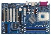
...USB5 USB45E 1 1 FSB_SEL0 FSB_SEL1 nnVFiUdoilratcCraeh42ip0s0et DDR400 Top: Line In Center: Line Out Bottom: Mic In ATXPWR1 CLRCMOS2 K7NF2-RAID CMOS Battery LAN PHY 1.5V_AGP1 PCI 1 AGP 8X PCI 2 MCP-RAID Chipset SATA2 SATA Super I/O SATA1 USB2.0 4Mb BIOS AUDIO CODEC AUDIO1 1 JR1 JL1 GAME1 1 PCI 3 ATA133 ...IDE1 30.5cm (12.0-in) 7 8 9 10 11 12 13 1 PS2_USB_PWR1 Jumper 2 FID Jumpers (FID0, FID1, FID2, FID3, FID4) 3 CPU Socket 4 North Bridge Controller 5 CPU Fan Connector (CPU_FAN1) 6 184-pin DDR DIMM Slots (DDR1- 3) 7 AGP Slot (AGP1) 8 Secondary Serial ATA ...
...USB5 USB45E 1 1 FSB_SEL0 FSB_SEL1 nnVFiUdoilratcCraeh42ip0s0et DDR400 Top: Line In Center: Line Out Bottom: Mic In ATXPWR1 CLRCMOS2 K7NF2-RAID CMOS Battery LAN PHY 1.5V_AGP1 PCI 1 AGP 8X PCI 2 MCP-RAID Chipset SATA2 SATA Super I/O SATA1 USB2.0 4Mb BIOS AUDIO CODEC AUDIO1 1 JR1 JL1 GAME1 1 PCI 3 ATA133 ...IDE1 30.5cm (12.0-in) 7 8 9 10 11 12 13 1 PS2_USB_PWR1 Jumper 2 FID Jumpers (FID0, FID1, FID2, FID3, FID4) 3 CPU Socket 4 North Bridge Controller 5 CPU Fan Connector (CPU_FAN1) 6 184-pin DDR DIMM Slots (DDR1- 3) 7 AGP Slot (AGP1) 8 Secondary Serial ATA ...

User Manual
Page 10
... install motherboard components or change any component, ensure that the power is switched off or the power cord is detached from the wall socket before you uninstallany component, place it . Failure to do so may cause physical injuries to the chassis. To avoid damaging the motherboard...do so may cause severe damage to motherboard components. 2.1 Screw Holes Place screws into it on the carpet or the like. Chapter 2 Installation K7NF2-RAID isan ATX form factor (12.0-in x 7.8-in the bag that comes with the component. Before you and damages to the motherboard, peripherals, ...
... install motherboard components or change any component, ensure that the power is switched off or the power cord is detached from the wall socket before you uninstallany component, place it . Failure to do so may cause physical injuries to the chassis. To avoid damaging the motherboard...do so may cause severe damage to motherboard components. 2.1 Screw Holes Place screws into it on the carpet or the like. Chapter 2 Installation K7NF2-RAID isan ATX form factor (12.0-in x 7.8-in the bag that comes with the component. Before you and damages to the motherboard, peripherals, ...

User Manual
Page 11
... the CPU and the heatsink are securely fastened and in good contact with a speed of the CPU fan and heatsink vendors. 11 Unlock the socket by lifting the lever up to the instruction manuals of 600 MHz and higher require larger heatsink and cooling fan. Step 2. Step 4. The...that it fitsinplace. The CPU fits only in place, pressitfirmly on the side tab to secure the CPU. Step 3. Carefully insert the CPU into the socket to improve heat transfer. 2.3 CPU Installation Step 1. For proper installation, please kindly refer to a 90o angle. Thermal grease between the CPU and ...
... the CPU and the heatsink are securely fastened and in good contact with a speed of the CPU fan and heatsink vendors. 11 Unlock the socket by lifting the lever up to the instruction manuals of 600 MHz and higher require larger heatsink and cooling fan. Step 2. Step 4. The...that it fitsinplace. The CPU fits only in place, pressitfirmly on the side tab to secure the CPU. Step 3. Carefully insert the CPU into the socket to improve heat transfer. 2.3 CPU Installation Step 1. For proper installation, please kindly refer to a 90o angle. Thermal grease between the CPU and ...

Quick Installation Guide
Page 2
Motherboard Layout English 1 PS2_USB_PWR1 Jumper 2 FID Jumpers (FID0, FID1, FID2, FID3, FID4) 3 CPU Socket 4 North Bridge Controller 5 CPU Fan Connector (CPU_FAN1) 6 184-pin DDR DIMM Slots (DDR1- 3) 7 AGP Slot (AGP1) 8 Secondary Serial ATA Connector (SATA2) 9 Primary Serial ATA Connector (... Audio Connector: CD1 (Black) 27 ATX Power Connector (ATXPWR1) 28 Shared USB 2.0 Header (USB45E, Blue) 29 FSB Select Jumper (FSB_SEL1) 30 FSB Select Jumper (FSB_SEL0) 2 ASRock K7NF2-RAID Motherboard
Motherboard Layout English 1 PS2_USB_PWR1 Jumper 2 FID Jumpers (FID0, FID1, FID2, FID3, FID4) 3 CPU Socket 4 North Bridge Controller 5 CPU Fan Connector (CPU_FAN1) 6 184-pin DDR DIMM Slots (DDR1- 3) 7 AGP Slot (AGP1) 8 Secondary Serial ATA Connector (SATA2) 9 Primary Serial ATA Connector (... Audio Connector: CD1 (Black) 27 ATX Power Connector (ATXPWR1) 28 Shared USB 2.0 Header (USB45E, Blue) 29 FSB Select Jumper (FSB_SEL1) 30 FSB Select Jumper (FSB_SEL0) 2 ASRock K7NF2-RAID Motherboard
Quick Installation Guide
Page 5
...3) ASRock I/O PlusTM: 1 PS/2 keyboard port, 1 PS/2 mouse port; 1 serial port: COM1; 1 parallel port: ECP/EPP support; 1 RJ 45 port; 6 default USB 2.0 ports; 1.2 Specifications Platform: ATX Form Factor (12.0-in x 7.8-in, 30.5-cm x 19.8-cm) CPU: Supports Socket A (462 pins) for 3 DDR DIMM slots, Max. 3GB; South Bridge: MCP-RAID, ...: 802.3u (10/100 Ethernet), supports Wake-On-LAN Hardware Monitor: CPU temperature sensing; Audio Jack: Line Out / Line In / Microphone English 5 ASRock K7NF2-RAID Motherboard IDE: IDE1: ATA 133 / Ultra DMA Mode 6; Chassis fan tachometer;
...3) ASRock I/O PlusTM: 1 PS/2 keyboard port, 1 PS/2 mouse port; 1 serial port: COM1; 1 parallel port: ECP/EPP support; 1 RJ 45 port; 6 default USB 2.0 ports; 1.2 Specifications Platform: ATX Form Factor (12.0-in x 7.8-in, 30.5-cm x 19.8-cm) CPU: Supports Socket A (462 pins) for 3 DDR DIMM slots, Max. 3GB; South Bridge: MCP-RAID, ...: 802.3u (10/100 Ethernet), supports Wake-On-LAN Hardware Monitor: CPU temperature sensing; Audio Jack: Line Out / Line In / Microphone English 5 ASRock K7NF2-RAID Motherboard IDE: IDE1: ATA 133 / Ultra DMA Mode 6; Chassis fan tachometer;

Quick Installation Guide
Page 7
... before touching any component, place it fits in the bag that comes with the component. 2.1 CPU Installation o STEP 1: Unlock the socket by the edges and do so may cause severe damage to avoid bending of the following precautions before you handle components. 3. STEP 3:...the socket such that it firmly on a grounded antstatic pad or in place. Whenever you uninstall any component. 2. STEP 4: When the CPU is locked. To avoid damaging the motherboard components due to static electricity, NEVER place your CPU fan and heatsink vendors. 7 ASRock K7NF2-RAID Motherboard...
... before touching any component, place it fits in the bag that comes with the component. 2.1 CPU Installation o STEP 1: Unlock the socket by the edges and do so may cause severe damage to avoid bending of the following precautions before you handle components. 3. STEP 3:...the socket such that it firmly on a grounded antstatic pad or in place. Whenever you uninstall any component. 2. STEP 4: When the CPU is locked. To avoid damaging the motherboard components due to static electricity, NEVER place your CPU fan and heatsink vendors. 7 ASRock K7NF2-RAID Motherboard...