User Guide
Page 4
...Specifications 2 1.3 Motherboard Layout 5 1.4 I/O Panel 7 Chapter 2 Installation 8 2.1 Installing the CPU 9 2.2 Installing the CPU Fan and Heatsink 12 2.3 Installing Memory Modules (DIMM) 13 2.4 Expansion Slots (PCI Express Slots) 15 2.5 Jumpers Setup 16 2.6 Onboard Headers and Connectors 17 Chapter 3 Software and Utilities Operation 21 3.1 Installing Drivers 21 3.2 Intel® Smart Connect Technology 22 3.3 ASRock Cloud 27 3.4 ASRock Live Update & APP Shop 37 3.4.1 UI Overview 37 3.4.2 Apps 38 3.4.3 BIOS & Drivers 41 3.4.4 Setting 42 Chapter 4 UEFI SETUP...
...Specifications 2 1.3 Motherboard Layout 5 1.4 I/O Panel 7 Chapter 2 Installation 8 2.1 Installing the CPU 9 2.2 Installing the CPU Fan and Heatsink 12 2.3 Installing Memory Modules (DIMM) 13 2.4 Expansion Slots (PCI Express Slots) 15 2.5 Jumpers Setup 16 2.6 Onboard Headers and Connectors 17 Chapter 3 Software and Utilities Operation 21 3.1 Installing Drivers 21 3.2 Intel® Smart Connect Technology 22 3.3 ASRock Cloud 27 3.4 ASRock Live Update & APP Shop 37 3.4.1 UI Overview 37 3.4.2 Apps 38 3.4.3 BIOS & Drivers 41 3.4.4 Setting 42 Chapter 4 UEFI SETUP...

User Guide
Page 5
4.1 Introduction 43 4.1.1 UEFI Menu Bar 43 4.1.2 Navigation Keys 44 4.2 Main Screen 45 4.3 OC Tweaker Screen 46 4.4 Advanced Screen 54 4.4.1 CPU Configuration 55 4.4.2 Chipset Configuration 57 4.4.3 Storage Configuration 59 4.4.4 Intel® Smart Connect Technology 60 4.4.5 Super IO Configuration 61 4.4.6 ACPI Configuration 62 4.4.7 USB Configuration 64 4.4.8 Trusted Computing 65 4.5 Tools 66 4.6 Hardware Health Event Monitoring Screen 68 4.7 Boot Screen 69 4.8 Security Screen 72 4.9 Exit Screen 73
4.1 Introduction 43 4.1.1 UEFI Menu Bar 43 4.1.2 Navigation Keys 44 4.2 Main Screen 45 4.3 OC Tweaker Screen 46 4.4 Advanced Screen 54 4.4.1 CPU Configuration 55 4.4.2 Chipset Configuration 57 4.4.3 Storage Configuration 59 4.4.4 Intel® Smart Connect Technology 60 4.4.5 Super IO Configuration 61 4.4.6 ACPI Configuration 62 4.4.7 USB Configuration 64 4.4.8 Trusted Computing 65 4.5 Tools 66 4.6 Hardware Health Event Monitoring Screen 68 4.7 Boot Screen 69 4.8 Security Screen 72 4.9 Exit Screen 73
User Guide
Page 6
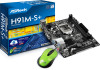
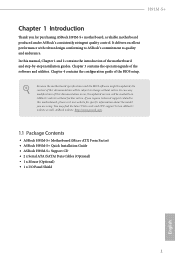
... guide of the BIOS setup. Because the motherboard specifications and the BIOS software might be updated, the content of the motherboard and step-by-step installation guides. ASRock website http://www.asrock.com. 1.1 Package Contents • ASRock H91M-S+ Motherboard (Micro ATX Form Factor) • ASRock H91M-S+ Quick Installation Guide • ASRock H91M-S+ Support CD • 2 x Serial ATA (SATA) Data Cables (Optional) • 1 x Mouse (Optional) • 1 x I/O Panel Shield 1 English It delivers excellent performance with robust design conforming to ASRock's commitment to change...
... guide of the BIOS setup. Because the motherboard specifications and the BIOS software might be updated, the content of the motherboard and step-by-step installation guides. ASRock website http://www.asrock.com. 1.1 Package Contents • ASRock H91M-S+ Motherboard (Micro ATX Form Factor) • ASRock H91M-S+ Quick Installation Guide • ASRock H91M-S+ Support CD • 2 x Serial ATA (SATA) Data Cables (Optional) • 1 x Mouse (Optional) • 1 x I/O Panel Shield 1 English It delivers excellent performance with robust design conforming to ASRock's commitment to change...
User Guide
Page 8
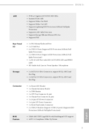
...45 LAN Port with LED (ACT/LINK LED and SPEED LED) • HD Audio Jack: Line in / Front Speaker / Microphone Storage • 2 x SATA3 6.0 Gb/s Connectors, support NCQ, AHCI and Hot Plug • 2 x SATA2 3.0 Gb/s Connectors, support NCQ, AHCI and Hot Plug Connector • 1 x Power LED Header • 1 x Chassis Intrusion Header • 1 x TPM Header • 1 x CPU Fan Connector (4-pin) • 1 x Chassis Fan Connector (4-pin) • 1 x 24 pin ATX Power Connector • 1 x 4 pin 12V Power Connector • 1 x Front Panel Audio Connector • 2 x USB 2.0 Headers (Support 4 USB...
...45 LAN Port with LED (ACT/LINK LED and SPEED LED) • HD Audio Jack: Line in / Front Speaker / Microphone Storage • 2 x SATA3 6.0 Gb/s Connectors, support NCQ, AHCI and Hot Plug • 2 x SATA2 3.0 Gb/s Connectors, support NCQ, AHCI and Hot Plug Connector • 1 x Power LED Header • 1 x Chassis Intrusion Header • 1 x TPM Header • 1 x CPU Fan Connector (4-pin) • 1 x Chassis Fan Connector (4-pin) • 1 x 24 pin ATX Power Connector • 1 x 4 pin 12V Power Connector • 1 x Front Panel Audio Connector • 2 x USB 2.0 Headers (Support 4 USB...
User Guide
Page 9
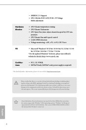
... CPU tem- perature) • CPU/Chassis Fan multi-speed control • CASE OPEN detection • Voltage monitoring: +12V, +5V, +3.3V, CPU Vcore OS • Microsoft® Windows® 10 32-bit / 10 64-bit / 8.1 32-bit / 8.1 64- You can use . Overclocking may be done at your system. Due to utilize the memory that there is a certain risk involved with overclocking, including adjusting the setting in the BIOS, applying Untied Overclocking Technology, or using thirdparty overclocking...
... CPU tem- perature) • CPU/Chassis Fan multi-speed control • CASE OPEN detection • Voltage monitoring: +12V, +5V, +3.3V, CPU Vcore OS • Microsoft® Windows® 10 32-bit / 10 64-bit / 8.1 32-bit / 8.1 64- You can use . Overclocking may be done at your system. Due to utilize the memory that there is a certain risk involved with overclocking, including adjusting the setting in the BIOS, applying Untied Overclocking Technology, or using thirdparty overclocking...

User Guide
Page 11
Description 1 CPU Fan Connector (CPU_FAN1) 2 2 x 240-pin DDR3 DIMM Slots (DDR3_A1, DDR3_B1) 3 ATX Power Connector (ATXPWR1) 4 System Panel Header (PANEL1) 5 SATA2 Connector (SATA_2) 6 SATA2 Connector (SATA_3) 7 Power LED Header (PLED1) 8 TPM Header (TPMS1) 9 USB 2.0 Header (USB4_5) 10 USB 2.0 Header (USB6_7) 11 SATA3 Connector (SATA_1) 12 SATA3 Connector (SATA_0) 13 Chassis Fan Connector (CHA_FAN1) 14 Chassis Speaker Header (SPEAKER1) 15 Chassis Intrusion Header (CI1) 16 Clear CMOS Jumper (CLRCMOS1) 17 Front Panel Audio Header (HD_AUDIO1) 18 ATX 12V Power Connector (ATX12V1) 6 English No.
Description 1 CPU Fan Connector (CPU_FAN1) 2 2 x 240-pin DDR3 DIMM Slots (DDR3_A1, DDR3_B1) 3 ATX Power Connector (ATXPWR1) 4 System Panel Header (PANEL1) 5 SATA2 Connector (SATA_2) 6 SATA2 Connector (SATA_3) 7 Power LED Header (PLED1) 8 TPM Header (TPMS1) 9 USB 2.0 Header (USB4_5) 10 USB 2.0 Header (USB6_7) 11 SATA3 Connector (SATA_1) 12 SATA3 Connector (SATA_0) 13 Chassis Fan Connector (CHA_FAN1) 14 Chassis Speaker Header (SPEAKER1) 15 Chassis Intrusion Header (CI1) 16 Clear CMOS Jumper (CLRCMOS1) 17 Front Panel Audio Header (HD_AUDIO1) 18 ATX 12V Power Connector (ATX12V1) 6 English No.

User Guide
Page 13
... your chassis to ensure that comes with the components. • When placing screws to secure the motherboard to unplug the power cord before you handle the components. • Hold components by the edges and do so may damage the motherboard. 8 English Failure to use a grounded wrist strap or touch a safety grounded object before installing or removing the motherboard. Pre-installation...
... your chassis to ensure that comes with the components. • When placing screws to secure the motherboard to unplug the power cord before you handle the components. • Hold components by the edges and do so may damage the motherboard. 8 English Failure to use a grounded wrist strap or touch a safety grounded object before installing or removing the motherboard. Pre-installation...

User Guide
Page 20
Please read the documentation of the expansion card and make sure that the power supply is switched off or the power cord is used for PCI Express x1 lane width graphics cards. PCIe slots: PCIE1 (PCIe 2.0 x1 slot) is used for the card before you start the installation. PCIE2 (PCIe 2.0 x16 slot) is unplugged. Before installing an expansion card, please make necessary hardware settings for PCI Express x16 lane width graphics cards. 15 English H91M-S+ 2.4 Expansion Slots (PCI Express Slots) There are 2 PCI Express slots on the motherboard.
Please read the documentation of the expansion card and make sure that the power supply is switched off or the power cord is used for PCI Express x1 lane width graphics cards. PCIe slots: PCIE1 (PCIe 2.0 x1 slot) is used for the card before you start the installation. PCIE2 (PCIe 2.0 x16 slot) is unplugged. Before installing an expansion card, please make necessary hardware settings for PCI Express x16 lane width graphics cards. 15 English H91M-S+ 2.4 Expansion Slots (PCI Express Slots) There are 2 PCI Express slots on the motherboard.

User Guide
Page 21
... the password, date, time, and user default profile will be detected. English 16 If you to short pin2 and pin3 on the pins, the jumper is removed. Please adjust the BIOS option "Clear Status" to default setup, please turn off the computer and unplug the power cord from the power supply. Clear CMOS Jumper (CLRCMOS1) (see p.5, No. 16) Default Clear CMOS CLRCMOS1 allows you clear the CMOS, the case open may be cleared only if the CMOS battery...
... the password, date, time, and user default profile will be detected. English 16 If you to short pin2 and pin3 on the pins, the jumper is removed. Please adjust the BIOS option "Clear Status" to default setup, please turn off the computer and unplug the power cord from the power supply. Clear CMOS Jumper (CLRCMOS1) (see p.5, No. 16) Default Clear CMOS CLRCMOS1 allows you clear the CMOS, the case open may be cleared only if the CMOS battery...

User Guide
Page 22
...panel. A front panel module mainly consists of power switch, reset switch, power LED, hard drive activity LED, speaker and etc. Placing jumper caps over these headers and connectors. The front panel design may configure the way to perform a normal restart. RESET (Reset Switch): Connect to the pin assignments below. System Panel Header (9-pin PANEL1) (see p.5, No. 4) GND PWRBTN# PLEDPLED+ GND RESET# GND HDLEDHDLED+ 1 Connect the power switch, reset switch and system status indicator on the chassis to the hard drive activity LED on the chassis front panel. H91M-S+ 2.6 Onboard...
...panel. A front panel module mainly consists of power switch, reset switch, power LED, hard drive activity LED, speaker and etc. Placing jumper caps over these headers and connectors. The front panel design may configure the way to perform a normal restart. RESET (Reset Switch): Connect to the pin assignments below. System Panel Header (9-pin PANEL1) (see p.5, No. 4) GND PWRBTN# PLEDPLED+ GND RESET# GND HDLEDHDLED+ 1 Connect the power switch, reset switch and system status indicator on the chassis to the hard drive activity LED on the chassis front panel. H91M-S+ 2.6 Onboard...

User Guide
Page 23
... the panel wire on this motherboard. USB 2.0 Headers (9-pin USB4_5) (see p.5, No. 9) (9-pin USB6_7) (see p.5, No. 11) SATA_0 SATA_1 These two SATA3 connectors support SATA data cables for the HD audio panel only. If you use an AC'97 audio panel, please install it to MIC2_L. Serial ATA3 Connectors (SATA_0: see p.5, No. 12) (SATA_1: see p.5, No. 10) DUMMY GND P+7 P-7 USB_PWR GND P+6 P-6 USB_PWR 1 Besides four USB 2.0 ports on the I/O panel, there are for internal storage devices...
... the panel wire on this motherboard. USB 2.0 Headers (9-pin USB4_5) (see p.5, No. 9) (9-pin USB6_7) (see p.5, No. 11) SATA_0 SATA_1 These two SATA3 connectors support SATA data cables for the HD audio panel only. If you use an AC'97 audio panel, please install it to MIC2_L. Serial ATA3 Connectors (SATA_0: see p.5, No. 12) (SATA_1: see p.5, No. 10) DUMMY GND P+7 P-7 USB_PWR GND P+6 P-6 USB_PWR 1 Besides four USB 2.0 ports on the I/O panel, there are for internal storage devices...
User Guide
Page 26
... be auto-detected and listed on the file "ASRSETUP.EXE" in your CD-ROM drive. Utilities Menu The Utilities Menu shows the application software that enhance the motherboard's features. "KB2720599": http://support.microsoft.com/kb/2720599/en-us 21 English To improve Windows 7 compatibility, please download and install the following hot fix provided by Microsoft. Therefore, the drivers you install can work properly. If the Main Menu does not appear automatically, locate...
... be auto-detected and listed on the file "ASRSETUP.EXE" in your CD-ROM drive. Utilities Menu The Utilities Menu shows the application software that enhance the motherboard's features. "KB2720599": http://support.microsoft.com/kb/2720599/en-us 21 English To improve Windows 7 compatibility, please download and install the following hot fix provided by Microsoft. Therefore, the drivers you install can work properly. If the Main Menu does not appear automatically, locate...
User Guide
Page 27
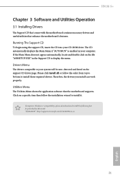
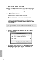
... system is already installed under IDE mode, directly changing the SATA mode to AHCI may cause Windows 8/7 to crash while booting. Press Win + R simultaneously in Windows Registry Editor. or 64-bit edition) • Set the SATA mode to avoid loss. 1. Please backup any important data before operating to AHCI. Double click on OK. 22 English 3.2 Intel® Smart Connect Technology Intel® Smart Connect Technology is a feature that periodically wakes your computer from...
... system is already installed under IDE mode, directly changing the SATA mode to AHCI may cause Windows 8/7 to crash while booting. Press Win + R simultaneously in Windows Registry Editor. or 64-bit edition) • Set the SATA mode to avoid loss. 1. Please backup any important data before operating to AHCI. Double click on OK. 22 English 3.2 Intel® Smart Connect Technology Intel® Smart Connect Technology is a feature that periodically wakes your computer from...

User Guide
Page 48
... Power-On-Self-Test (POST) will it make BIOS setup less difficult but also a lot more amusing. Because the UEFI software is a blend of the screen has a menu bar with its test routines. Not only will continue with the following selections: Main For setting system time/date information OC Tweaker For overclocking configurations Advanced For advanced system configurations Tool Useful tools H/W Monitor Displays current hardware status Boot...
... Power-On-Self-Test (POST) will it make BIOS setup less difficult but also a lot more amusing. Because the UEFI software is a blend of the screen has a menu bar with its test routines. Not only will continue with the following selections: Main For setting system time/date information OC Tweaker For overclocking configurations Advanced For advanced system configurations Tool Useful tools H/W Monitor Displays current hardware status Boot...

User Guide
Page 62
4.4.2 Chipset Configuration H91M-S+ Primary Graphics Adapter Select a primary VGA. Onboard HD Audio Enable/disable onboard HD audio. IGPU Multi-Monitor Select disable to disable the integrated graphics when an external graphics card is idle for PCIE1. Render Standby Power down the render unit when the GPU is installed. Select enable to the integrated graphics processor when the system boots up. Share Memory Configure the size of memory that is installed. 57 English Set to Auto to enable onboard HD audio and automatically disable it when...
4.4.2 Chipset Configuration H91M-S+ Primary Graphics Adapter Select a primary VGA. Onboard HD Audio Enable/disable onboard HD audio. IGPU Multi-Monitor Select disable to disable the integrated graphics when an external graphics card is idle for PCIE1. Render Standby Power down the render unit when the GPU is installed. Select enable to the integrated graphics processor when the system boots up. Share Memory Configure the size of memory that is installed. 57 English Set to Auto to enable onboard HD audio and automatically disable it when...

User Guide
Page 63
... system will start to boot up when the power recovers. Onboard LAN Enable or disable the onboard network interface controller. Deep Sleep Configure deep sleep mode for power saving when the computer is selected, the power will also automatically switch off when the power recovers. It will remain off the Power and Keyboard LEDs when the system enters into Standby/Hibernation mode. 58 English If [Power Off] is shut down. Front Panel Enable/disable front panel HD audio. Restore...
... system will start to boot up when the power recovers. Onboard LAN Enable or disable the onboard network interface controller. Deep Sleep Configure deep sleep mode for power saving when the computer is selected, the power will also automatically switch off when the power recovers. It will remain off the Power and Keyboard LEDs when the system enters into Standby/Hibernation mode. 58 English If [Power Off] is shut down. Front Panel Enable/disable front panel HD audio. Restore...
User Guide
Page 69
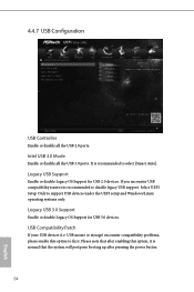
...USB compatibility issues it . Legacy USB 3.0 Support Enable or disable Legacy OS Support for USB 2.0 devices. It is recommended to fix it is normal that the system will postpone booting up after enabling this option to select [Smart Auto]. USB Compatibility Patch If your USB devices (i.e. 4.4.7 USB Configuration USB Controller Enable or disable all the USB 3.0 ports. Intel USB 3.0 Mode Enable or disable all the USB 2.0 ports. USB mouse or storage) encounter compatibility problems, please enable this option, it is recommended to support USB devices under the UEFI setup...
...USB compatibility issues it . Legacy USB 3.0 Support Enable or disable Legacy OS Support for USB 2.0 devices. It is recommended to fix it is normal that the system will postpone booting up after enabling this option to select [Smart Auto]. USB Compatibility Patch If your USB devices (i.e. 4.4.7 USB Configuration USB Controller Enable or disable all the USB 3.0 ports. Intel USB 3.0 Mode Enable or disable all the USB 2.0 ports. USB mouse or storage) encounter compatibility problems, please enable this option, it is recommended to support USB devices under the UEFI setup...
User Guide
Page 71
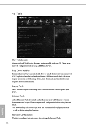
... Network Configuration Use this function. Please setup network configuration before using this to update your UEFI. Internet Flash ASRock Internet Flash downloads and updates the latest UEFI firmware version from our support CD, Easy Driver Installer is recommended to plug in the UEFI that installs the LAN driver to your PC. 4.5 Tools UEFI Tech Service Contact ASRock Tech Service if you . Instant Flash Save UEFI files in your USB storage device and run Instant Flash to configure internet connection settings for you are having trouble with your system via an USB storage...
... Network Configuration Use this function. Please setup network configuration before using this to update your UEFI. Internet Flash ASRock Internet Flash downloads and updates the latest UEFI firmware version from our support CD, Easy Driver Installer is recommended to plug in the UEFI that installs the LAN driver to your PC. 4.5 Tools UEFI Tech Service Contact ASRock Tech Service if you . Instant Flash Save UEFI files in your USB storage device and run Instant Flash to configure internet connection settings for you are having trouble with your system via an USB storage...

User Guide
Page 72
Load User Default Load previously saved user defaults. 67 English Save User Default Type a profile name and press enter to download the UEFI firmware. H91M-S+ Internet Setting Enable or disable sound effects in the setup utility. UEFI Download Server Select a server to save your settings as user default.
Load User Default Load previously saved user defaults. 67 English Save User Default Type a profile name and press enter to download the UEFI firmware. H91M-S+ Internet Setting Enable or disable sound effects in the setup utility. UEFI Download Server Select a server to save your settings as user default.

User Guide
Page 73
CPU Fan 1 Setting Select a fan mode for CPU Fans 1, or choose Customize to set 5 CPU temperatures and assign a respective fan speed for each temperature. Case Open Feature Enable or disable Case Open Feature to monitor the status of the hardware on your system, including the parameters of the CPU temperature, motherboard temperature, fan speed and voltage. 4.6 Hardware Health Event Monitoring Screen This section allows you to detect whether the chassis cover has been removed. 68 English Chassis Fan 1 Setting Select a fan mode for Chassis Fan 1, or choose...
CPU Fan 1 Setting Select a fan mode for CPU Fans 1, or choose Customize to set 5 CPU temperatures and assign a respective fan speed for each temperature. Case Open Feature Enable or disable Case Open Feature to monitor the status of the hardware on your system, including the parameters of the CPU temperature, motherboard temperature, fan speed and voltage. 4.6 Hardware Health Event Monitoring Screen This section allows you to detect whether the chassis cover has been removed. 68 English Chassis Fan 1 Setting Select a fan mode for Chassis Fan 1, or choose...


