
Quick Installation Guide
Page 3
PS2 Mouse PS2 Keyboard Motherboard Layout CPU_FAN1 ATX12V1 H81M-VG4 R4.0 DDR3_A1 (64 bit, 240-pin module) DDR3_B1 (64 bit, 240-pin module) ATXPWR1 VGA1 PLED PWRBTN 1 HDLED RESET PANEL1 USB 3.2 Gen1 T: USB3_0 B: USB3_1 USB 2.0 T: USB2 B: USB3 Top: RJ-45 HD_AUDIO1 1 Top: LINE IN Center: FRONT Bottom: MIC IN RoHS Audio CODEC LAN H81M-VG4 Intel 1 H81 SATA_0 SATA_1 SATA_2 SATA_3 PCIE1 CLRMOS1 1 SPI_TPM_J1 BIOS ROM CMOS Battery 1 TPMS1 PCIE2 USB6_7 USB4_5 1 1 CHA_FAN1 SPK_CI1 1 English 1
PS2 Mouse PS2 Keyboard Motherboard Layout CPU_FAN1 ATX12V1 H81M-VG4 R4.0 DDR3_A1 (64 bit, 240-pin module) DDR3_B1 (64 bit, 240-pin module) ATXPWR1 VGA1 PLED PWRBTN 1 HDLED RESET PANEL1 USB 3.2 Gen1 T: USB3_0 B: USB3_1 USB 2.0 T: USB2 B: USB3 Top: RJ-45 HD_AUDIO1 1 Top: LINE IN Center: FRONT Bottom: MIC IN RoHS Audio CODEC LAN H81M-VG4 Intel 1 H81 SATA_0 SATA_1 SATA_2 SATA_3 PCIE1 CLRMOS1 1 SPI_TPM_J1 BIOS ROM CMOS Battery 1 TPMS1 PCIE2 USB6_7 USB4_5 1 1 CHA_FAN1 SPK_CI1 1 English 1
Quick Installation Guide
Page 7
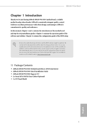
...; ASRock H81M-VG4 R4.0 Motherboard (Micro ATX Form Factor) • ASRock H81M-VG4 R4.0 Quick Installation Guide • ASRock H81M-VG4 R4.0 Support CD • 2 x Serial ATA (SATA) Data Cables (Optional) • 1 x I/O Panel Shield 5 English If you require technical support related to this documentation will be updated, the content of this documentation occur, the updated version will be subject to quality and endurance. Because the motherboard specifications and the BIOS software might be available on ASRock's website as well. In case any...
...; ASRock H81M-VG4 R4.0 Motherboard (Micro ATX Form Factor) • ASRock H81M-VG4 R4.0 Quick Installation Guide • ASRock H81M-VG4 R4.0 Support CD • 2 x Serial ATA (SATA) Data Cables (Optional) • 1 x I/O Panel Shield 5 English If you require technical support related to this documentation will be updated, the content of this documentation occur, the updated version will be subject to quality and endurance. Because the motherboard specifications and the BIOS software might be available on ASRock's website as well. In case any...

Quick Installation Guide
Page 8
... use an HD front panel audio module and enable the multi-channel audio feature through the audio driver. • Supports Surge Protection • ELNA Audio Caps 6 shared memory 1024MB * The size of system memory: 16GB (see CAUTION) • Supports Intel® Extreme Memory Profile (XMP) 1.3/1.2 Expansion Slot • 1 x PCI Express 2.0 x16 Slot (PCIE2: x16 mode) • 1 x PCI Express 2.0 x1 Slot Graphics * Intel® HD Graphics Built-in Visuals and the VGA outputs can be supported only with processors...
... use an HD front panel audio module and enable the multi-channel audio feature through the audio driver. • Supports Surge Protection • ELNA Audio Caps 6 shared memory 1024MB * The size of system memory: 16GB (see CAUTION) • Supports Intel® Extreme Memory Profile (XMP) 1.3/1.2 Expansion Slot • 1 x PCI Express 2.0 x16 Slot (PCIE2: x16 mode) • 1 x PCI Express 2.0 x1 Slot Graphics * Intel® HD Graphics Built-in Visuals and the VGA outputs can be supported only with processors...

Quick Installation Guide
Page 9
...Connectors, support NCQ, AHCI and Hot Plug Connector • 1 x Chassis Intrusion and Speaker Header • 1 x TPM Header • 1 x SPI TPM Header • 1 x CPU Fan Connector (4-pin) • 1 x Chassis Fan Connector (4-pin) • 1 x 24 pin ATX Power Connector • 1 x 4 pin 12V Power Connector • 1 x Front Panel Audio Connector • 2 x USB 2.0 Headers (Support 4 USB 2.0 ports) (Supports ESD Protection) BIOS Feature • AMI UEFI Legal BIOS with multilingual GUI support • ACPI 1.1 Compliant wake up events • SMBIOS 2.3.1 support • CPU, DRAM Voltage...
...Connectors, support NCQ, AHCI and Hot Plug Connector • 1 x Chassis Intrusion and Speaker Header • 1 x TPM Header • 1 x SPI TPM Header • 1 x CPU Fan Connector (4-pin) • 1 x Chassis Fan Connector (4-pin) • 1 x 24 pin ATX Power Connector • 1 x 4 pin 12V Power Connector • 1 x Front Panel Audio Connector • 2 x USB 2.0 Headers (Support 4 USB 2.0 ports) (Supports ESD Protection) BIOS Feature • AMI UEFI Legal BIOS with multilingual GUI support • ACPI 1.1 Compliant wake up events • SMBIOS 2.3.1 support • CPU, DRAM Voltage...

Quick Installation Guide
Page 11
... install motherboard components or change any components, place them on a carpet. Failure to do not overtighten the screws! Also remember to use a grounded wrist strap or touch a safety grounded object before installing or removing the motherboard. Before you uninstall any motherboard settings. • Make sure to the motherboard's components, NEVER place your chassis to the chassis, please do so may damage the motherboard. 9 English H81M-VG4 R4...
... install motherboard components or change any components, place them on a carpet. Failure to do not overtighten the screws! Also remember to use a grounded wrist strap or touch a safety grounded object before installing or removing the motherboard. Before you uninstall any motherboard settings. • Make sure to the motherboard's components, NEVER place your chassis to the chassis, please do so may damage the motherboard. 9 English H81M-VG4 R4...

Quick Installation Guide
Page 18
2.4 Expansion Slots (PCI Express Slots) There are 2 PCI Express slots on the motherboard. PCIe slots: PCIE1 (PCIe 2.0 x1 slot) is used for PCI Express x16 lane width graphics cards. 16 English Please read the documentation of the expansion card and make sure that the power supply is switched off or the power cord is used for the card before you start the installation. PCIE2 (PCIe 2.0 x16 slot) is unplugged. Before installing an expansion card, please make necessary hardware settings for PCI Express x1 lane width cards.
2.4 Expansion Slots (PCI Express Slots) There are 2 PCI Express slots on the motherboard. PCIe slots: PCIE1 (PCIe 2.0 x1 slot) is used for PCI Express x16 lane width graphics cards. 16 English Please read the documentation of the expansion card and make sure that the power supply is switched off or the power cord is used for the card before you start the installation. PCIE2 (PCIe 2.0 x16 slot) is unplugged. Before installing an expansion card, please make necessary hardware settings for PCI Express x1 lane width cards.

Quick Installation Guide
Page 19
... clear and reset the system parameters to short the pins on CLRMOS1 for 15 seconds, use a jumper cap to default setup, please turn off the computer and unplug the power cord from the power supply. After waiting for 5 seconds. Please be noted that the password, date, time, and user default profile will be detected. Please adjust the BIOS option "Clear Status" to clear the CMOS when you just finish updating the BIOS...
... clear and reset the system parameters to short the pins on CLRMOS1 for 15 seconds, use a jumper cap to default setup, please turn off the computer and unplug the power cord from the power supply. After waiting for 5 seconds. Please be noted that the password, date, time, and user default profile will be detected. Please adjust the BIOS option "Clear Status" to clear the CMOS when you just finish updating the BIOS...
Quick Installation Guide
Page 21
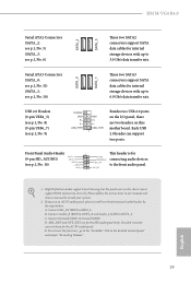
... internal storage devices with up to the front panel audio header by the steps below: A. H81M-VG4 R4.0 Serial ATA2 Connectors (SATA_2: see p.1, No. 5) (SATA_3: see p.1, No. 6) SATA_2 SATA_3 These two SATA2 connectors support SATA data cables for internal storage devices with up to connect them for the AC'97 audio panel. You don't need to 3.0 Gb/s data transfer rate. USB 2.0 Headers (9-pin USB4_5) (see p.1, No. 8) (9-pin USB6_7) (see p.1, No. 9) Besides two USB 2.0 ports on the chassis must support...
... internal storage devices with up to the front panel audio header by the steps below: A. H81M-VG4 R4.0 Serial ATA2 Connectors (SATA_2: see p.1, No. 5) (SATA_3: see p.1, No. 6) SATA_2 SATA_3 These two SATA2 connectors support SATA data cables for internal storage devices with up to connect them for the AC'97 audio panel. You don't need to 3.0 Gb/s data transfer rate. USB 2.0 Headers (9-pin USB4_5) (see p.1, No. 8) (9-pin USB6_7) (see p.1, No. 9) Besides two USB 2.0 ports on the chassis must support...

User Manual
Page 4
... 1 1.2 Specifications 2 1.3 Motherboard Layout 5 1.4 I/O Panel 7 Chapter 2 Installation 9 2.1 Installing the CPU 10 2.2 Installing the CPU Fan and Heatsink 13 2.3 Installing Memory Modules (DIMM) 14 2.4 Expansion Slots (PCI Express Slots) 16 2.5 Jumpers Setup 17 2.6 Onboard Headers and Connectors 18 Chapter 3 Software and Utilities Operation 22 3.1 Installing Drivers 22 3.2 Intel® Smart Connect Technology 23 3.3 ASRock Live Update & APP Shop 28 3.3.1 UI Overview 28 3.3.2 Apps 29 3.3.3 BIOS & Drivers 32 3.3.4 Setting 33 Chapter 4 UEFI SETUP UTILITY 34...
... 1 1.2 Specifications 2 1.3 Motherboard Layout 5 1.4 I/O Panel 7 Chapter 2 Installation 9 2.1 Installing the CPU 10 2.2 Installing the CPU Fan and Heatsink 13 2.3 Installing Memory Modules (DIMM) 14 2.4 Expansion Slots (PCI Express Slots) 16 2.5 Jumpers Setup 17 2.6 Onboard Headers and Connectors 18 Chapter 3 Software and Utilities Operation 22 3.1 Installing Drivers 22 3.2 Intel® Smart Connect Technology 23 3.3 ASRock Live Update & APP Shop 28 3.3.1 UI Overview 28 3.3.2 Apps 29 3.3.3 BIOS & Drivers 32 3.3.4 Setting 33 Chapter 4 UEFI SETUP UTILITY 34...
User Manual
Page 6
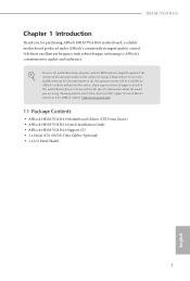
.... Chapter 3 contains the operation guide of this documentation occur, the updated version will be updated, the content of the motherboard and step-by-step installation guides. In case any modifications of the software and utilities. ASRock website http://www.asrock.com. 1.1 Package Contents • ASRock H81M-VG4 R4.0 Motherboard (Micro ATX Form Factor) • ASRock H81M-VG4 R4.0 Quick Installation Guide • ASRock H81M-VG4 R4.0 Support CD • 2 x Serial ATA (SATA) Data Cables (Optional) • 1 x I/O Panel Shield 1 English In this manual, Chapter 1 and 2 contains...
.... Chapter 3 contains the operation guide of this documentation occur, the updated version will be updated, the content of the motherboard and step-by-step installation guides. In case any modifications of the software and utilities. ASRock website http://www.asrock.com. 1.1 Package Contents • ASRock H81M-VG4 R4.0 Motherboard (Micro ATX Form Factor) • ASRock H81M-VG4 R4.0 Quick Installation Guide • ASRock H81M-VG4 R4.0 Support CD • 2 x Serial ATA (SATA) Data Cables (Optional) • 1 x I/O Panel Shield 1 English In this manual, Chapter 1 and 2 contains...

User Manual
Page 8
...Connectors, support NCQ, AHCI and Hot Plug Connector • 1 x Chassis Intrusion and Speaker Header • 1 x TPM Header • 1 x SPI TPM Header • 1 x CPU Fan Connector (4-pin) • 1 x Chassis Fan Connector (4-pin) • 1 x 24 pin ATX Power Connector • 1 x 4 pin 12V Power Connector • 1 x Front Panel Audio Connector • 2 x USB 2.0 Headers (Support 4 USB 2.0 ports) (Supports ESD Protection) BIOS Feature • AMI UEFI Legal BIOS with multilingual GUI support • ACPI 1.1 Compliant wake up events • SMBIOS 2.3.1 support • CPU, DRAM Voltage...
...Connectors, support NCQ, AHCI and Hot Plug Connector • 1 x Chassis Intrusion and Speaker Header • 1 x TPM Header • 1 x SPI TPM Header • 1 x CPU Fan Connector (4-pin) • 1 x Chassis Fan Connector (4-pin) • 1 x 24 pin ATX Power Connector • 1 x 4 pin 12V Power Connector • 1 x Front Panel Audio Connector • 2 x USB 2.0 Headers (Support 4 USB 2.0 ports) (Supports ESD Protection) BIOS Feature • AMI UEFI Legal BIOS with multilingual GUI support • ACPI 1.1 Compliant wake up events • SMBIOS 2.3.1 support • CPU, DRAM Voltage...

User Manual
Page 22
... default setup, please turn off the computer and unplug the power cord from the power supply. When the jumper cap is placed on the pins, the jumper is removed. Please be noted that the password, date, time, and user default profile will be detected. English 17 Clear CMOS Jumper (CLRMOS1) (see p.5, No. 15) 2-pin Jumper CLRMOS1 allows you clear the CMOS, the case open may be cleared only if the CMOS battery is "Open". H81M-VG4 R4.0 2.5 Jumpers Setup...
... default setup, please turn off the computer and unplug the power cord from the power supply. When the jumper cap is placed on the pins, the jumper is removed. Please be noted that the password, date, time, and user default profile will be detected. English 17 Clear CMOS Jumper (CLRMOS1) (see p.5, No. 15) 2-pin Jumper CLRMOS1 allows you clear the CMOS, the case open may be cleared only if the CMOS battery is "Open". H81M-VG4 R4.0 2.5 Jumpers Setup...

User Manual
Page 27
... the Main Menu does not appear automatically, locate and double click on a specific item then follow the order from top to bottom to display the menu. Drivers Menu The drivers compatible to install it. Click on the file "ASRSETUP.EXE" in your CD-ROM drive. Therefore, the drivers you install can work properly. "KB2720599": http://support.microsoft.com/kb/2720599/en-us 22 English Utilities Menu The Utilities Menu shows the application software...
... the Main Menu does not appear automatically, locate and double click on a specific item then follow the order from top to bottom to display the menu. Drivers Menu The drivers compatible to install it. Click on the file "ASRSETUP.EXE" in your CD-ROM drive. Therefore, the drivers you install can work properly. "KB2720599": http://support.microsoft.com/kb/2720599/en-us 22 English Utilities Menu The Utilities Menu shows the application software...

User Manual
Page 28
... wakes your motherboard supports this feature. • Operating system: Microsoft Windows 8.1/8/7 (32- Press Win + R simultaneously in Windows 8.1/8/7, type "Regedit" into HKEY_LOCAL_MACHINE\SYSTEM\CurrentControlSet\services\ msahci in AHCI mode, please follow the instructions below. There are certain risks. Enter into the word box then click OK. 2. Click on the value Start and change the value from Windows® sleep state to avoid loss. 1. H81M-VG4 R4.0 3.2 Intel® Smart Connect Technology Intel® Smart Connect Technology...
... wakes your motherboard supports this feature. • Operating system: Microsoft Windows 8.1/8/7 (32- Press Win + R simultaneously in Windows 8.1/8/7, type "Regedit" into HKEY_LOCAL_MACHINE\SYSTEM\CurrentControlSet\services\ msahci in AHCI mode, please follow the instructions below. There are certain risks. Enter into the word box then click OK. 2. Click on the value Start and change the value from Windows® sleep state to avoid loss. 1. H81M-VG4 R4.0 3.2 Intel® Smart Connect Technology Intel® Smart Connect Technology...

User Manual
Page 39
... system configuration tools, cool sound effects and stunning visuals. If you power on . Because the UEFI software is a blend of the screen has a menu bar with its test routines. Chapter 4 UEFI SETUP UTILITY 4.1 Introduction ASRock Interactive UEFI is constantly being updated, the following selections: Main For setting system time/date information OC Tweaker For overclocking configurations Advanced For advanced system configurations Tool Useful tools H/W Monitor Displays current hardware status Boot For configuring boot settings and boot...
... system configuration tools, cool sound effects and stunning visuals. If you power on . Because the UEFI software is a blend of the screen has a menu bar with its test routines. Chapter 4 UEFI SETUP UTILITY 4.1 Introduction ASRock Interactive UEFI is constantly being updated, the following selections: Main For setting system time/date information OC Tweaker For overclocking configurations Advanced For advanced system configurations Tool Useful tools H/W Monitor Displays current hardware status Boot For configuring boot settings and boot...

User Manual
Page 52
... graphics card is installed. PCIE2 Link Speed Select the link speed for lower power consumption. Onboard HD Audio Enable/disable onboard HD audio. Render Standby Power down the render unit when the GPU is installed. 47 English 4.4.2 Chipset Configuration H81M-VG4 R4.0 Primary Graphics Adapter Select a primary VGA. Share Memory Configure the size of memory that is allocated to enable onboard HD audio and automatically disable it when a sound card is idle for PCIE2. Set to Auto to the integrated graphics processor when the system boots...
... graphics card is installed. PCIE2 Link Speed Select the link speed for lower power consumption. Onboard HD Audio Enable/disable onboard HD audio. Render Standby Power down the render unit when the GPU is installed. 47 English 4.4.2 Chipset Configuration H81M-VG4 R4.0 Primary Graphics Adapter Select a primary VGA. Share Memory Configure the size of memory that is allocated to enable onboard HD audio and automatically disable it when a sound card is idle for PCIE2. Set to Auto to the integrated graphics processor when the system boots...

User Manual
Page 53
If [Power Off] is selected, the power will start to boot up when the power recovers. 48 English If [Power On] is shut down. Onboard LAN Enable or disable the onboard network interface controller. Restore on AC/Power Loss Select the power state after a power failure. Front Panel Enable/disable front panel HD audio. Deep Sleep Configure deep sleep mode for power saving when the computer is selected, the system will remain off when the power recovers.
If [Power Off] is selected, the power will start to boot up when the power recovers. 48 English If [Power On] is shut down. Onboard LAN Enable or disable the onboard network interface controller. Restore on AC/Power Loss Select the power state after a power failure. Front Panel Enable/disable front panel HD audio. Deep Sleep Configure deep sleep mode for power saving when the computer is selected, the system will remain off when the power recovers.

User Manual
Page 58
...postpone booting up after pressing the power button. 53 English If you encounter USB compatibility issues it is normal that after enabling this option to disable legacy USB support. Select UEFI Setup Only to select [Smart Auto]. Intel USB 3.0 Mode Enable or disable all the USB 2.0 ports. It is recommended to fix it. 4.4.6 USB Configuration H81M-VG4 R4.0 USB Controller Enable or disable all the USB 3.0 ports. USB mouse or storage) encounter compatibility problems, please enable this option, it is recommended to support USB devices under the UEFI setup and Windows/Linux...
...postpone booting up after pressing the power button. 53 English If you encounter USB compatibility issues it is normal that after enabling this option to disable legacy USB support. Select UEFI Setup Only to select [Smart Auto]. Intel USB 3.0 Mode Enable or disable all the USB 2.0 ports. It is recommended to fix it. 4.4.6 USB Configuration H81M-VG4 R4.0 USB Controller Enable or disable all the USB 3.0 ports. USB mouse or storage) encounter compatibility problems, please enable this option, it is recommended to support USB devices under the UEFI setup and Windows/Linux...
User Manual
Page 60
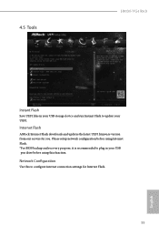
Please setup network configuration before using Internet Flash. *For BIOS backup and recovery purpose, it is recommended to configure internet connection settings for you. Network Configuration Use this function. Internet Flash ASRock Internet Flash downloads and updates the latest UEFI firmware version from our servers for Internet Flash. 55 English 4.5 Tools H81M-VG4 R4.0 Instant Flash Save UEFI files in your USB storage device and run Instant Flash to update your USB pen drive before using this to plug in your UEFI.
Please setup network configuration before using Internet Flash. *For BIOS backup and recovery purpose, it is recommended to configure internet connection settings for you. Network Configuration Use this function. Internet Flash ASRock Internet Flash downloads and updates the latest UEFI firmware version from our servers for Internet Flash. 55 English 4.5 Tools H81M-VG4 R4.0 Instant Flash Save UEFI files in your USB storage device and run Instant Flash to update your USB pen drive before using this to plug in your UEFI.

User Manual
Page 61
...disk drive to install the drivers from our support CD, Easy Driver Installer is enabled, the computer will power on automatically to your system via an USB storage device, then downloads and installs the other required drivers automatically. Easy Driver Installer For users that installs the LAN driver to dehumidify the system after entering S4/S5 state. Please setup network configuration before using UEFI Tech Service. Load User Default 56 Load previously saved user defaults. English Save User Default Type a profile name and press enter to download the UEFI firmware. UEFI Download...
...disk drive to install the drivers from our support CD, Easy Driver Installer is enabled, the computer will power on automatically to your system via an USB storage device, then downloads and installs the other required drivers automatically. Easy Driver Installer For users that installs the LAN driver to dehumidify the system after entering S4/S5 state. Please setup network configuration before using UEFI Tech Service. Load User Default 56 Load previously saved user defaults. English Save User Default Type a profile name and press enter to download the UEFI firmware. UEFI Download...


