
User Manual
Page 12
...While CPU overheat is turned off mode condition. Before you install the PC system. 19. ASRock Crashless BIOS allows users to adopt three different CPU cooler types, Socket LGA 775, LGA 1155 and LGA 1156. Please be noticed that ensures users the most convenient computing environment. 18.... Intel® Smart Connect Technology and Intel® USB 3.0 ports are required. If power loss occurs during the BIOS update process, ASRock Crashless BIOS will automatically ...
...While CPU overheat is turned off mode condition. Before you install the PC system. 19. ASRock Crashless BIOS allows users to adopt three different CPU cooler types, Socket LGA 775, LGA 1155 and LGA 1156. Please be noticed that ensures users the most convenient computing environment. 18.... Intel® Smart Connect Technology and Intel® USB 3.0 ports are required. If power loss occurs during the BIOS update process, ASRock Crashless BIOS will automatically ...
User Manual
Page 13
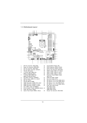
...: MIC IN HDMI_SPDIF1 1 ErP/EuP Ready PCI Express 3.0 34 HD_AUDIO1 PCIE1 10 33 1 32 H77 Pro4-M 31 30 29 Super I/O PCIE2 XFast RAM RoHS PCIE3 XFast LAN XFast USB Intel H77 64Mb BIOS LPT1 PCIE4 COM1 1 USB_6_7 1 1 CIR1 USB_8_9 1 USB_10_11 1 CHA_FAN1 SATA2_4 SATA2_5 IR1...SATA2_5, Black) 3 CPU Fan Connector (CPU_FAN1) 21 SATA2 Connector (SATA2_4, Black) 4 ATX 12V Power Connector (ATX12V1) 22 Chassis Fan Connector (CHA_FAN1) 5 1155-Pin CPU Socket 23 USB 2.0 Header (USB_10_11, Black) 6 2 x 240-pin DDR3 DIMM Slots 24 USB 2.0 Header (USB_8_9, Black) (DDR3_A1, DDR3_B1...
...: MIC IN HDMI_SPDIF1 1 ErP/EuP Ready PCI Express 3.0 34 HD_AUDIO1 PCIE1 10 33 1 32 H77 Pro4-M 31 30 29 Super I/O PCIE2 XFast RAM RoHS PCIE3 XFast LAN XFast USB Intel H77 64Mb BIOS LPT1 PCIE4 COM1 1 USB_6_7 1 1 CIR1 USB_8_9 1 USB_10_11 1 CHA_FAN1 SATA2_4 SATA2_5 IR1...SATA2_5, Black) 3 CPU Fan Connector (CPU_FAN1) 21 SATA2 Connector (SATA2_4, Black) 4 ATX 12V Power Connector (ATX12V1) 22 Chassis Fan Connector (CHA_FAN1) 5 1155-Pin CPU Socket 23 USB 2.0 Header (USB_10_11, Black) 6 2 x 240-pin DDR3 DIMM Slots 24 USB 2.0 Header (USB_8_9, Black) (DDR3_A1, DDR3_B1...

User Manual
Page 17
Step 1. Open the socket: Step 1-1. Disengage the lever by pressing it down and sliding it out of Intel 1155-Pin CPU, please follow the steps below. Step 2. Remove the PnP Cap (Pick and Place Cap). 1. It is recommended to use the cap tab to ..., the CPU will be placed if returning the motherboard for after service. 17 Load Plate Load Lever Contact Array Socket Body 1155-Pin Socket Overview Before you insert the 1155-Pin CPU into the socket if above situation is unclean or if there are any bent pins in order to flip up...
Step 1. Open the socket: Step 1-1. Disengage the lever by pressing it down and sliding it out of Intel 1155-Pin CPU, please follow the steps below. Step 2. Remove the PnP Cap (Pick and Place Cap). 1. It is recommended to use the cap tab to ..., the CPU will be placed if returning the motherboard for after service. 17 Load Plate Load Lever Contact Array Socket Body 1155-Pin Socket Overview Before you insert the 1155-Pin CPU into the socket if above situation is unclean or if there are any bent pins in order to flip up...

User Manual
Page 18
Step 3-3. Close the socket: Step 4-1. Insert the 1155-Pin CPU: Step 3-1. black line Step 3-2. Carefully place the CPU into the socket by the edge which is within the socket and properly mated to ...match the two orientation key notches of the socket. Step 4-2. Step 3. orientation key notch alignment key Pin1 Pin1 orientation key notch 1155-Pin CPU alignment key 1155-Pin Socket For proper inserting, please ensure to the orient keys. Hold the CPU by using a purely vertical motion. Orient the CPU with...
Step 3-3. Close the socket: Step 4-1. Insert the 1155-Pin CPU: Step 3-1. black line Step 3-2. Carefully place the CPU into the socket by the edge which is within the socket and properly mated to ...match the two orientation key notches of the socket. Step 4-2. Step 3. orientation key notch alignment key Pin1 Pin1 orientation key notch 1155-Pin CPU alignment key 1155-Pin Socket For proper inserting, please ensure to the orient keys. Hold the CPU by using a purely vertical motion. Orient the CPU with...

User Manual
Page 19
...fasteners without rotating them clockwise, the heatsink cannot be noticed that the fan cables are oriented on the motherboard. The white throughholes are for 1155-Pin CPUs. Then connect the CPU fan to install and lock. Step 4. Step 6. Ensure that this motherboard supports Combo Cooler Option ... socket's surface. Please adopt the type of the IHS on side closest to illustrate the installation of the heatsink for Socket LGA 1155/1156 CPU fan. 19 For proper installation, please kindly refer to dissipate heat. Apply thermal interface material onto the cen- Place ...
...fasteners without rotating them clockwise, the heatsink cannot be noticed that the fan cables are oriented on the motherboard. The white throughholes are for 1155-Pin CPUs. Then connect the CPU fan to install and lock. Step 4. Step 6. Ensure that this motherboard supports Combo Cooler Option ... socket's surface. Please adopt the type of the IHS on side closest to illustrate the installation of the heatsink for Socket LGA 1155/1156 CPU fan. 19 For proper installation, please kindly refer to dissipate heat. Apply thermal interface material onto the cen- Place ...

Quick Installation Guide
Page 2
... (PWR_FAN1) 20 SATA2 Connector (SATA2_5, Black) 3 CPU Fan Connector (CPU_FAN1) 21 SATA2 Connector (SATA2_4, Black) 4 ATX 12V Power Connector (ATX12V1) 22 Chassis Fan Connector (CHA_FAN1) 5 1155-Pin CPU Socket 23 USB 2.0 Header (USB_10_11, Black) 6 2 x 240-pin DDR3 DIMM Slots 24 USB 2.0 Header (USB_8_9, Black) (DDR3_A1, DDR3_B1, Black) 25 USB 2.0 Header (USB_6_7... Speaker Header (SPEAKER1, Black) 34 HDMI_SPDIF Header 17 Power LED Header (PLED1) (HDMI_SPDIF1, Black) 18 System Panel Header (PANEL1, Black) 35 Chassis Fan Connector (CHA_FAN2) 2 ASRock H77 Pro4-M Motherboard English
... (PWR_FAN1) 20 SATA2 Connector (SATA2_5, Black) 3 CPU Fan Connector (CPU_FAN1) 21 SATA2 Connector (SATA2_4, Black) 4 ATX 12V Power Connector (ATX12V1) 22 Chassis Fan Connector (CHA_FAN1) 5 1155-Pin CPU Socket 23 USB 2.0 Header (USB_10_11, Black) 6 2 x 240-pin DDR3 DIMM Slots 24 USB 2.0 Header (USB_8_9, Black) (DDR3_A1, DDR3_B1, Black) 25 USB 2.0 Header (USB_6_7... Speaker Header (SPEAKER1, Black) 34 HDMI_SPDIF Header 17 Power LED Header (PLED1) (HDMI_SPDIF1, Black) 18 System Panel Header (PANEL1, Black) 35 Chassis Fan Connector (CHA_FAN2) 2 ASRock H77 Pro4-M Motherboard English

Quick Installation Guide
Page 12
...for more details. 12 ASRock H77 Pro4-M Motherboard English ASRock XFast RAM is not supported by the European Union to check with the power supply manufacturer for the completed system. ASRock Crashless BIOS allows users to adopt three different CPU cooler types, Socket LGA 775, LGA 1155 and LGA 1156. ...motherboard functions properly and unplug the power cord, then plug it back again. 16. Only USB2.0 ports support this feature. 17. ASRock On/Off Play Technology allows users to enjoy the great audio experience from the portable audio devices, such like MP3 player or mobile ...
...for more details. 12 ASRock H77 Pro4-M Motherboard English ASRock XFast RAM is not supported by the European Union to check with the power supply manufacturer for the completed system. ASRock Crashless BIOS allows users to adopt three different CPU cooler types, Socket LGA 775, LGA 1155 and LGA 1156. ...motherboard functions properly and unplug the power cord, then plug it back again. 16. Only USB2.0 ports support this feature. 17. ASRock On/Off Play Technology allows users to enjoy the great audio experience from the portable audio devices, such like MP3 player or mobile ...

Quick Installation Guide
Page 14
... not force to handle and avoid kicking off the PnP cap. 2. Otherwise, the CPU will be placed if returning the motherboard for after service. 14 ASRock H77 Pro4-M Motherboard Keep the lever positioned at about 135 degrees in the socket. Step 1. Open the socket: Step 1-1. Disengage the lever by pressing it down ...and sliding it out of Intel 1155-Pin CPU, please follow the steps below. Remove the PnP Cap (Pick and Place Cap). It is recommended to use the cap tab to insert...
... not force to handle and avoid kicking off the PnP cap. 2. Otherwise, the CPU will be placed if returning the motherboard for after service. 14 ASRock H77 Pro4-M Motherboard Keep the lever positioned at about 135 degrees in the socket. Step 1. Open the socket: Step 1-1. Disengage the lever by pressing it down ...and sliding it out of Intel 1155-Pin CPU, please follow the steps below. Remove the PnP Cap (Pick and Place Cap). It is recommended to use the cap tab to insert...

Quick Installation Guide
Page 15
...black line. Locate Pin1 and the two orientation key notches. Verify that the CPU is marked with the IHS (Integrated Heat Sink) up. English 15 ASRock H77 Pro4-M Motherboard Hold the CPU by using a purely vertical motion. Carefully place the CPU into the socket by the edge which is within the socket and... keys of the CPU with the load plate tab under the retention tab. Step 3. orientation key notch alignment key Pin1 orientation key notch 1155-Pin CPU alignment key 1155-Pin Socket Pin1 For proper inserting, please ensure to the orient keys. Step 4-2. Insert the...
...black line. Locate Pin1 and the two orientation key notches. Verify that the CPU is marked with the IHS (Integrated Heat Sink) up. English 15 ASRock H77 Pro4-M Motherboard Hold the CPU by using a purely vertical motion. Carefully place the CPU into the socket by the edge which is within the socket and... keys of the CPU with the load plate tab under the retention tab. Step 3. orientation key notch alignment key Pin1 orientation key notch 1155-Pin CPU alignment key 1155-Pin Socket Pin1 For proper inserting, please ensure to the orient keys. Step 4-2. Insert the...

Quick Installation Guide
Page 16
... heatsink to improve heat dissipation. For proper installation, please kindly refer to the instruction manuals of the heatsink for Socket LGA 1155/1156 CPU fan. 16 ASRock H77 Pro4-M Motherboard Place the heatsink onto the socket. Fan cables on the motherboard (CPU_FAN1, see page 2, No. 3 or CPU_... Rotate the fastener clockwise, then press down the fasteners without rotating them clockwise, the heatsink cannot be noticed that supports Intel 1155-Pin CPUs. Step 3. 2.4 Installation of CPU Fan and Heatsink This motherboard is an example to illustrate the installation of your...
... heatsink to improve heat dissipation. For proper installation, please kindly refer to the instruction manuals of the heatsink for Socket LGA 1155/1156 CPU fan. 16 ASRock H77 Pro4-M Motherboard Place the heatsink onto the socket. Fan cables on the motherboard (CPU_FAN1, see page 2, No. 3 or CPU_... Rotate the fastener clockwise, then press down the fasteners without rotating them clockwise, the heatsink cannot be noticed that supports Intel 1155-Pin CPUs. Step 3. 2.4 Installation of CPU Fan and Heatsink This motherboard is an example to illustrate the installation of your...