
Intel Rapid Storage Guide
Page 12
... Enter to RAID. 5. Switch the SATA Operation Mode option to select the physical disks. 6. Enable RAID in System BIOS Use the instructions included with your motherboard to enable RAID in the system BIOS, a RAID volume must be created, and the F6 installation method must be used to load the Intel®...
... Enter to RAID. 5. Switch the SATA Operation Mode option to select the physical disks. 6. Enable RAID in System BIOS Use the instructions included with your motherboard to enable RAID in the system BIOS, a RAID volume must be created, and the F6 installation method must be used to load the Intel®...

User Manual
Page 2
...for identification or explanation and to the owners' benefit, without written consent of ASRock Inc. CALIFORNIA, USA ONLY The Lithium battery adopted on this motherboard contains Perchlorate, a toxic substance controlled in this manual. "Perchlorate Material-special handling may appear...damages (including damages for any interference received, including interference that may apply, see www.dtsc.ca.gov/hazardouswaste/perchlorate" ASRock Website: http://www.asrock.com 2 In no responsibility for loss of profits, loss of business, loss of data, interruption of business...
...for identification or explanation and to the owners' benefit, without written consent of ASRock Inc. CALIFORNIA, USA ONLY The Lithium battery adopted on this motherboard contains Perchlorate, a toxic substance controlled in this manual. "Perchlorate Material-special handling may appear...damages (including damages for any interference received, including interference that may apply, see www.dtsc.ca.gov/hazardouswaste/perchlorate" ASRock Website: http://www.asrock.com 2 In no responsibility for loss of profits, loss of business, loss of data, interruption of business...
User Manual
Page 3
... 6 1.3 Motherboard Layout 13 1.4 I/O Panel 14 2 Installation 16 2.1 Screw Holes 16 2.2 Pre-installation Precautions 16 2.3 CPU Installation 17 2.4 Installation of Heatsink and CPU fan 19 2.5 Installation of Memory Modules (DIMM 20 2.6 Expansion Slots (PCI Express Slots 22 2.7 CrossFireXTM and Quad CrossFireXTM Operation Guide 23 2.8 Dual Monitor and Surround Display Features 27 2.9 ASRock Smart...
... 6 1.3 Motherboard Layout 13 1.4 I/O Panel 14 2 Installation 16 2.1 Screw Holes 16 2.2 Pre-installation Precautions 16 2.3 CPU Installation 17 2.4 Installation of Heatsink and CPU fan 19 2.5 Installation of Memory Modules (DIMM 20 2.6 Expansion Slots (PCI Express Slots 22 2.7 CrossFireXTM and Quad CrossFireXTM Operation Guide 23 2.8 Dual Monitor and Surround Display Features 27 2.9 ASRock Smart...

User Manual
Page 5
... and endurance. In this manual will be updated, the content of this motherboard, please visit our website for purchasing ASRock H77 Pro4-M motherboard, a reliable motherboard produced under ASRock's consistently stringent quality control. In case any modifications of this ... motherboard specifications and the BIOS software might be available on ASRock website as well. www.asrock.com/support/index.asp 1.1 Package Contents ASRock H77 Pro4-M Motherboard (Micro ATX Form Factor: 9.6-in x 9.6-in, 24.4 cm x 24.4 cm) ASRock H77 Pro4-M Quick Installation Guide ASRock H77 Pro4-M...
... and endurance. In this manual will be updated, the content of this motherboard, please visit our website for purchasing ASRock H77 Pro4-M motherboard, a reliable motherboard produced under ASRock's consistently stringent quality control. In case any modifications of this ... motherboard specifications and the BIOS software might be available on ASRock website as well. www.asrock.com/support/index.asp 1.1 Package Contents ASRock H77 Pro4-M Motherboard (Micro ATX Form Factor: 9.6-in x 9.6-in, 24.4 cm x 24.4 cm) ASRock H77 Pro4-M Quick Installation Guide ASRock H77 Pro4-M...
User Manual
Page 10
... in a user-friendly interface, which includes Hardware Monitor, Fan Control, Overclocking, OC DNA and IES. ASRock website: http://www.asrock.com 10 For audio output, this motherboard supports both stereo and mono modes. Please visit our website for you implement Dual Channel Memory Technology, make...are only supported under Windows® 7 64-bit / 7. Please check Intel® website for proper connection. 9. Your friends then can use ASRock XFast RAM to use . 4. The maximum shared memory size is defined by the chipset vendor and is supported under Windows® 7...
... in a user-friendly interface, which includes Hardware Monitor, Fan Control, Overclocking, OC DNA and IES. ASRock website: http://www.asrock.com 10 For audio output, this motherboard supports both stereo and mono modes. Please visit our website for you implement Dual Channel Memory Technology, make...are only supported under Windows® 7 64-bit / 7. Please check Intel® website for proper connection. 9. Your friends then can use ASRock XFast RAM to use . 4. The maximum shared memory size is defined by the chipset vendor and is supported under Windows® 7...
User Manual
Page 11
...combines your most visited web sites, your history, your Facebook friends and your Apple devices, such as iPhone/iPad/iPod Touch, ASRock has prepared a wonderful solution for internet browsers, is included into the BIOS setup menu to update system BIOS without preparing an additional... reduces the frequency of previously visited websites, making web surfing faster than before. ASRock APP Charger allows you keep in Flash ROM. ASRock motherboards are transferring currently. 15. ASRock XFast RAM is a new function that it makes your iPhone charge much quickly from your ...
...combines your most visited web sites, your history, your Facebook friends and your Apple devices, such as iPhone/iPad/iPod Touch, ASRock has prepared a wonderful solution for internet browsers, is included into the BIOS setup menu to update system BIOS without preparing an additional... reduces the frequency of previously visited websites, making web surfing faster than before. ASRock APP Charger allows you keep in Flash ROM. ASRock motherboards are transferring currently. 15. ASRock XFast RAM is a new function that it makes your iPhone charge much quickly from your ...

User Manual
Page 12
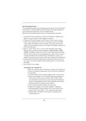
ASRock Crashless BIOS allows users to update their BIOS without fear of the completed system should be under 100 mA current consumption. This motherboard also provides a free 3.5mm audio cable (optional) that not all the 775 and 1156 CPU Fan can be used. 20. Intel® Smart Connect ... details. 12 Please note that BIOS files need to Intel's suggestion, the EuP ready power supply must meet EuP standards, an EuP ready motherboard and an EuP ready power supply are not supported by Microsoft® Windows® XP / XP 64-bit. According to be noticed that ensures ...
ASRock Crashless BIOS allows users to update their BIOS without fear of the completed system should be under 100 mA current consumption. This motherboard also provides a free 3.5mm audio cable (optional) that not all the 775 and 1156 CPU Fan can be used. 20. Intel® Smart Connect ... details. 12 Please note that BIOS files need to Intel's suggestion, the EuP ready power supply must meet EuP standards, an EuP ready motherboard and an EuP ready power supply are not supported by Microsoft® Windows® XP / XP 64-bit. According to be noticed that ensures ...
User Manual
Page 13
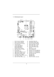
1.3 Motherboard Layout 12 3 4 USB 2.0 T: USB0 B: USB1 PS2 Keyboard CPU_FAN2 CPU_FAN1 PWR_FAN1 ATX12V1 5... 1 ErP/EuP Ready PCI Express 3.0 34 HD_AUDIO1 PCIE1 10 33 1 32 H77 Pro4-M 31 30 29 Super I/O PCIE2 XFast RAM RoHS PCIE3 XFast LAN XFast USB Intel H77 64Mb BIOS LPT1 PCIE4 COM1 1 USB_6_7 1 1 CIR1 USB_8_9 1 USB_10_11 1 ...Connector (ATXPWR1) 27 COM Port Header (COM1) 9 USB 3.0 Header (USB3_12_13, Black) 28 Print Port Header (LPT1) 10 Intel H77 Chipset 29 PCI Express 2.0 x16 Slot (PCIE4, Black) 11 SPI Flash Memory (64Mb) 30 PCI Express 2.0 x16 Slot (PCIE3...
1.3 Motherboard Layout 12 3 4 USB 2.0 T: USB0 B: USB1 PS2 Keyboard CPU_FAN2 CPU_FAN1 PWR_FAN1 ATX12V1 5... 1 ErP/EuP Ready PCI Express 3.0 34 HD_AUDIO1 PCIE1 10 33 1 32 H77 Pro4-M 31 30 29 Super I/O PCIE2 XFast RAM RoHS PCIE3 XFast LAN XFast USB Intel H77 64Mb BIOS LPT1 PCIE4 COM1 1 USB_6_7 1 1 CIR1 USB_8_9 1 USB_10_11 1 ...Connector (ATXPWR1) 27 COM Port Header (COM1) 9 USB 3.0 Header (USB3_12_13, Black) 28 Print Port Header (LPT1) 10 Intel H77 Chipset 29 PCI Express 2.0 x16 Slot (PCIE4, Black) 11 SPI Flash Memory (64Mb) 30 PCI Express 2.0 x16 Slot (PCIE3...

User Manual
Page 16
... component, place it . When placing screws into the holes indicated by the edges and do so may cause physical injuries to ensure that the motherboard fits into it on the carpet or the like. board to the chassis, please do so may cause severe damage to do not ...- static pad or in the bag that the power is switched off or the power cord is a micro ATX form factor (9.6" x 9.6", 24.4 x 24.4 cm) motherboard. Before you handle the components. 3. Also remember to do not over -tighten the screws! Chapter 2: Installation This is detached from the wall socket before touching...
... component, place it . When placing screws into the holes indicated by the edges and do so may cause physical injuries to ensure that the motherboard fits into it on the carpet or the like. board to the chassis, please do so may cause severe damage to do not ...- static pad or in the bag that the power is switched off or the power cord is a micro ATX form factor (9.6" x 9.6", 24.4 x 24.4 cm) motherboard. Before you handle the components. 3. Also remember to do not over -tighten the screws! Chapter 2: Installation This is detached from the wall socket before touching...

User Manual
Page 17
... 1155-Pin CPU into the socket if above situation is found. Open the socket: Step 1-1. Step 1-2. Otherwise, the CPU will be placed if returning the motherboard for after service. 17 This cap must be seriously damaged. Remove the PnP Cap (Pick and Place Cap). 1. 2.3 CPU Installation For the installation of the...
... 1155-Pin CPU into the socket if above situation is found. Open the socket: Step 1-1. Step 1-2. Otherwise, the CPU will be placed if returning the motherboard for after service. 17 This cap must be seriously damaged. Remove the PnP Cap (Pick and Place Cap). 1. 2.3 CPU Installation For the installation of the...

User Manual
Page 19
...three different CPU cooler types, Socket LGA 775, LGA 1155 and LGA 1156. Then connect the CPU fan to install and lock. Repeat with the motherboard throughholes. Step 6. Step 3. Connect fan header with thumb to the CPU_FAN connector (CPU_ FAN1, see page 13, No. 3 or CPU_FAN2, see... Intel 1155Pin CPU to improve heat dissipation. Please adopt the type of heatsink and cooling fan compliant with 1155-Pin socket that this motherboard supports Combo Cooler Option (C.C.O.), which provides flexible options to MB header Fastener slots pointing straight out Press Down (4 Places) If...
...three different CPU cooler types, Socket LGA 775, LGA 1155 and LGA 1156. Then connect the CPU fan to install and lock. Repeat with the motherboard throughholes. Step 6. Step 3. Connect fan header with thumb to the CPU_FAN connector (CPU_ FAN1, see page 13, No. 3 or CPU_FAN2, see... Intel 1155Pin CPU to improve heat dissipation. Please adopt the type of heatsink and cooling fan compliant with 1155-Pin socket that this motherboard supports Combo Cooler Option (C.C.O.), which provides flexible options to MB header Fastener slots pointing straight out Press Down (4 Places) If...
User Manual
Page 20
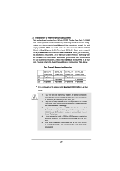
...Table below. Black slots; If only one memory module or three memory modules are installed in the DDR3 DIMM slots on this motherboard. otherwise, this motherboard. 20 For dual channel configuration, you want to install two memory modules, for optimal compatibility and reliability, it ...is recommended to install them on this motherboard, it is unable to activate Dual Channel Memory Technology. 4. You may be activated. It is not recommended to install them in the...
...Table below. Black slots; If only one memory module or three memory modules are installed in the DDR3 DIMM slots on this motherboard. otherwise, this motherboard. 20 For dual channel configuration, you want to install two memory modules, for optimal compatibility and reliability, it ...is recommended to install them on this motherboard, it is unable to activate Dual Channel Memory Technology. 4. You may be activated. It is not recommended to install them in the...

User Manual
Page 21
... clips outward. Firmly insert the DIMM into the slot in place and the DIMM is properly seated. 21 Installing a DIMM Please make sure to the motherboard and the DIMM if you force the DIMM into the slot until the retaining clips at both ends fully snap back in incorrect orientation. It...
... clips outward. Firmly insert the DIMM into the slot in place and the DIMM is properly seated. 21 Installing a DIMM Please make sure to the motherboard and the DIMM if you force the DIMM into the slot until the retaining clips at both ends fully snap back in incorrect orientation. It...

User Manual
Page 22
...a chassis fan to the chassis with the slot and press firmly until the card is unplugged. Step 2. Fasten the card to the motherboard's chassis fan connector (CHA_FAN1 or CHA_FAN2) when using multiple graphics cards for PCI Express x16 lane width graphics cards, or to install PCI Express...install an Ivy Bridge CPU. Step 5. Installing an expansion card Step 1. Replace the system cover. 22 Remove the system unit cover (if your motherboard is used for installing ASRock Game Blaster. 1. In CrossFireXTM mode, please install the PCI Express x16 graphics cards on this...
...a chassis fan to the chassis with the slot and press firmly until the card is unplugged. Step 2. Fasten the card to the motherboard's chassis fan connector (CHA_FAN1 or CHA_FAN2) when using multiple graphics cards for PCI Express x16 lane width graphics cards, or to install PCI Express...install an Ivy Bridge CPU. Step 5. Installing an expansion card Step 1. Replace the system cover. 22 Remove the system unit cover (if your motherboard is used for installing ASRock Game Blaster. 1. In CrossFireXTM mode, please install the PCI Express x16 graphics cards on this...

User Manual
Page 23
...card manuals for AMD CrossFireXTM driver updates. 1. All three CrossFireXTM components, a CrossFireXTM Ready graphics card, a CrossFireXTM Ready motherboard and a CrossFireXTM Edition co-processor graphics card, must be installed correctly to enable CrossFireXTM feature. Insert one Radeon graphics...VistaTM / 7 OS only. Please check AMD's website for detailed installation guide. 2.7 CrossFireXTM and Quad CrossFireXTM Operation Guide This motherboard supports CrossFireXTM and Quad CrossFireXTM. Step 1. If a customer incorrectly configures their system they will operate as 12-...
...card manuals for AMD CrossFireXTM driver updates. 1. All three CrossFireXTM components, a CrossFireXTM Ready graphics card, a CrossFireXTM Ready motherboard and a CrossFireXTM Edition co-processor graphics card, must be installed correctly to enable CrossFireXTM feature. Insert one Radeon graphics...VistaTM / 7 OS only. Please check AMD's website for detailed installation guide. 2.7 CrossFireXTM and Quad CrossFireXTM Operation Guide This motherboard supports CrossFireXTM and Quad CrossFireXTM. Step 1. If a customer incorrectly configures their system they will operate as 12-...

User Manual
Page 24
... graphics card on the top of the Radeon graphics cards. (The CrossFire Bridge is provided with the graphics card you purchase, not bundled with this motherboard.
... graphics card on the top of the Radeon graphics cards. (The CrossFire Bridge is provided with the graphics card you purchase, not bundled with this motherboard.

User Manual
Page 27
... support CD to your system and restart your system boots. You can drive same or different display contents. This motherboard also provides independent display controllers for DVI-D, D-Sub and HDMI to this motherboard. Connect a DVI-D monitor cable to the DVI-D port on the I/O panel, connect a D-Sub monitor cable to the D-Sub port... HDMI + D-Sub. 27 D-Sub, DVI-D and HDMI monitors cannot be enabled at the same time. 2.8 Dual Monitor and Surround Display Features Dual Monitor Feature This motherboard supports dual monitor feature.
... support CD to your system and restart your system boots. You can drive same or different display contents. This motherboard also provides independent display controllers for DVI-D, D-Sub and HDMI to this motherboard. Connect a DVI-D monitor cable to the DVI-D port on the I/O panel, connect a D-Sub monitor cable to the D-Sub port... HDMI + D-Sub. 27 D-Sub, DVI-D and HDMI monitors cannot be enabled at the same time. 2.8 Dual Monitor and Surround Display Features Dual Monitor Feature This motherboard supports dual monitor feature.
User Manual
Page 28
...of the multi-monitors according to page 22 for the display icon identified by the number 2. A. Click "Extend my Windows desktop onto this motherboard. 4. Set the appropriate "Screen Resolution" and "Color Quality" for the second monitor. Click "Apply" or "OK" to enter UEFI setup. G....PCI Express VGA card driver to this monitor". Please refer to the following steps to the HDMI port on each monitor. Surround Display Feature This motherboard supports surround display upgrade. Connect a DVI-D monitor cable to the DVI-D port on the I/O panel, connect a D-Sub monitor cable to...
...of the multi-monitors according to page 22 for the display icon identified by the number 2. A. Click "Extend my Windows desktop onto this motherboard. 4. Set the appropriate "Screen Resolution" and "Color Quality" for the second monitor. Click "Apply" or "OK" to enter UEFI setup. G....PCI Express VGA card driver to this monitor". Please refer to the following steps to the HDMI port on each monitor. Surround Display Feature This motherboard supports surround display upgrade. Connect a DVI-D monitor cable to the DVI-D port on the I/O panel, connect a D-Sub monitor cable to...

User Manual
Page 29
... that supports HDCP function as a monitor, television or projector. C. The placement of your change. HDCP is my main monitor" and "Extend the desktop onto this motherboard. HDCP stands for High-Bandwidth Digital Content Protection, a specification developed by the number three to save your monitors that you would like to...
... that supports HDCP function as a monitor, television or projector. C. The placement of your change. HDCP is my main monitor" and "Extend the desktop onto this motherboard. HDCP stands for High-Bandwidth Digital Content Protection, a specification developed by the number three to save your monitors that you would like to...

User Manual
Page 30
...) CIR header (4-pin, gray) Step2. Multi-Angle CIR Receiver is only supported by some of ASRock Smart Remote. Please refer to ASRock's website for the quick installation and usage of ASRock's motherboards. Connect the front USB cable to below , pin 1-5) and the CIR header. Please make sure... pin assignments are matched correctly. 1 23 45 Step3. Please install it on ASRock motherboard. Please refer to the USB_PWR USB 2.0 header (as below procedures for the motherboard support list: http://www.asrock.com 30 Only one of the chassis on the market. 3. Multi-Angle CIR...
...) CIR header (4-pin, gray) Step2. Multi-Angle CIR Receiver is only supported by some of ASRock Smart Remote. Please refer to ASRock's website for the quick installation and usage of ASRock's motherboards. Connect the front USB cable to below , pin 1-5) and the CIR header. Please make sure... pin assignments are matched correctly. 1 23 45 Step3. Please install it on ASRock motherboard. Please refer to the USB_PWR USB 2.0 header (as below procedures for the motherboard support list: http://www.asrock.com 30 Only one of the chassis on the market. 3. Multi-Angle CIR...


