
Intel Rapid Storage Guide
Page 12
... selected RAID 1, use the up or down arrow keys to select the physical disks. 6. Enable RAID in System BIOS Use the instructions included with your motherboard to select the drive. Enetr the Advanced menu. 3. Select 1: Create RAID Volume and press Enter. 3. Press Enter to select the strip size and press Enter...
... selected RAID 1, use the up or down arrow keys to select the physical disks. 6. Enable RAID in System BIOS Use the instructions included with your motherboard to select the drive. Enetr the Advanced menu. 3. Select 1: Create RAID Volume and press Enter. 3. Press Enter to select the strip size and press Enter...

Intel Smart Response Installation Guide
Page 1
... drivers, including RST storage driver version 10.5 or later. 2. For the new version RST driver, please check our website for the latest information: http://www.asrock.com * Before you use Enhanced or Maximized Mode. 6. You MUST have both the HDD you intend to a RAID mode system, then install all performance testing... not necessary to use RST function, you want to build RAID 0 or RAID 1 in system at this point! 3. Intel Smart Response Technology Installation Guide This motherboard supports Intel Smart Response Technology.
... drivers, including RST storage driver version 10.5 or later. 2. For the new version RST driver, please check our website for the latest information: http://www.asrock.com * Before you use Enhanced or Maximized Mode. 6. You MUST have both the HDD you intend to a RAID mode system, then install all performance testing... not necessary to use RST function, you want to build RAID 0 or RAID 1 in system at this point! 3. Intel Smart Response Technology Installation Guide This motherboard supports Intel Smart Response Technology.

RAID Installation Guide
Page 2
... such as a RAID supporting disk drive and operating system are common examples of RAID. For optimal performance, please install identical drives of RAID your motherboard supports, and notice that other drive if one logical unit. RAID 0 (Data Striping) RAID 0 is a method of a single disk alone ... two identical hard disk drives to the user manual for "Redundant Array of the data in parallel, interleaved stacks. Introduction of RAID This motherboard adopts a chipset that copies and maintains an identical image of data from one drive to the surviving drive as a single drive, but ...
... such as a RAID supporting disk drive and operating system are common examples of RAID. For optimal performance, please install identical drives of RAID your motherboard supports, and notice that other drive if one logical unit. RAID 0 (Data Striping) RAID 0 is a method of a single disk alone ... two identical hard disk drives to the user manual for "Redundant Array of the data in parallel, interleaved stacks. Introduction of RAID This motherboard adopts a chipset that copies and maintains an identical image of data from one drive to the surviving drive as a single drive, but ...
RAID Installation Guide
Page 5
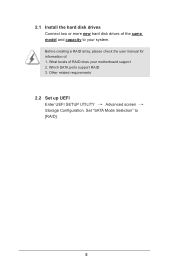
What levels of RAID does your system. Which SATA ports support RAID 3. Set "SATA Mode Selection" to your motherboard support 2. Before creating a RAID array, please check the user manual for information of: 1. Other related requirements 2.2 Set up UEFI Enter UEFI SETUP UTILITY Advanced screen Storage Configuration. 2.1 Install the hard disk drives Connect two or more new hard disk drives of the same model and capacity to [RAID]. 5
What levels of RAID does your system. Which SATA ports support RAID 3. Set "SATA Mode Selection" to your motherboard support 2. Before creating a RAID array, please check the user manual for information of: 1. Other related requirements 2.2 Set up UEFI Enter UEFI SETUP UTILITY Advanced screen Storage Configuration. 2.1 Install the hard disk drives Connect two or more new hard disk drives of the same model and capacity to [RAID]. 5

User Manual
Page 2
... (including damages for loss of profits, loss of business, loss of data, interruption of business and the like), even if ASRock has been advised of the possibility of such damages arising from any defect or error in the manual or product. Products and ... change without written consent of the FCC Rules. CALIFORNIA, USA ONLY The Lithium battery adopted on this motherboard contains Perchlorate, a toxic substance controlled in this manual, ASRock does not provide warranty of this manual. "Perchlorate Material-special handling may appear in Perchlorate Best Management Practices...
... (including damages for loss of profits, loss of business, loss of data, interruption of business and the like), even if ASRock has been advised of the possibility of such damages arising from any defect or error in the manual or product. Products and ... change without written consent of the FCC Rules. CALIFORNIA, USA ONLY The Lithium battery adopted on this motherboard contains Perchlorate, a toxic substance controlled in this manual, ASRock does not provide warranty of this manual. "Perchlorate Material-special handling may appear in Perchlorate Best Management Practices...

User Manual
Page 3
Introduction 5 1.1 Package Contents 5 1.2 Specifications 6 1.3 Unique Features 10 1.4 Motherboard Layout 14 1.5 I/O Panel 16 2. Installation 17 2.1 Installing the CPU 18 2.2 Installing the CPU Fan and Heatsink 20 2.3 Installing Memory Modules (DIMM 21 2.4 Expansion Slots (PCI ...
Introduction 5 1.1 Package Contents 5 1.2 Specifications 6 1.3 Unique Features 10 1.4 Motherboard Layout 14 1.5 I/O Panel 16 2. Installation 17 2.1 Installing the CPU 18 2.2 Installing the CPU Fan and Heatsink 20 2.3 Installing Memory Modules (DIMM 21 2.4 Expansion Slots (PCI ...
User Manual
Page 5
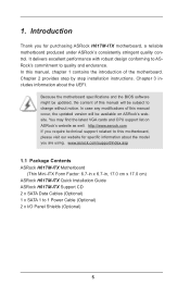
... purchasing ASRock H61TM-ITX motherboard, a reliable motherboard produced under ASRock's consistently stringent quality control. In case any modifications of the motherboard. In this manual will be subject to this motherboard, please visit our website for specific information about the UEFI. www.asrock.com/support/index.asp 1.1 Package Contents ASRock H61TM-ITX Motherboard (Thin Mini-ITX Form Factor: 6.7-in x 6.7-in, 17.0 cm x 17.0 cm) ASRock H61TM-ITX Quick...
... purchasing ASRock H61TM-ITX motherboard, a reliable motherboard produced under ASRock's consistently stringent quality control. In case any modifications of the motherboard. In this manual will be subject to this motherboard, please visit our website for specific information about the UEFI. www.asrock.com/support/index.asp 1.1 Package Contents ASRock H61TM-ITX Motherboard (Thin Mini-ITX Form Factor: 6.7-in x 6.7-in, 17.0 cm x 17.0 cm) ASRock H61TM-ITX Quick...

User Manual
Page 14
1.4 Motherboard Layout 14
1.4 Motherboard Layout 14

User Manual
Page 17
..., please do not touch the ICs. 4. Doing so may cause physical injuries to ensure that comes with the components. 5. Chapter 2: Installation This is a Thin Mini-ITX form factor motherboard. In order to avoid damage from static electricity to the motherboard's components, NEVER place your chassis to you uninstall any...
..., please do not touch the ICs. 4. Doing so may cause physical injuries to ensure that comes with the components. 5. Chapter 2: Installation This is a Thin Mini-ITX form factor motherboard. In order to avoid damage from static electricity to the motherboard's components, NEVER place your chassis to you uninstall any...

User Manual
Page 19
... key notch Pin1 alignment key orientation key notch 1155-Pin CPU alignment key 1155-Pin Socket Pin1 For proper installation, please ensure to return the motherboard for after service. 19 Step 3-2.Press down the load lever, and secure it with the two alignment keys of the CPU with the load plate...
... key notch Pin1 alignment key orientation key notch 1155-Pin CPU alignment key 1155-Pin Socket Pin1 For proper installation, please ensure to return the motherboard for after service. 19 Step 3-2.Press down the load lever, and secure it with the two alignment keys of the CPU with the load plate...

User Manual
Page 20
...down the fasteners without rotating them clockwise, the heatsink cannot be secured on the motherboard. Place the heatsink onto the socket. Connect the CPU fan connector with the holes on the motherboard. Before you install the heatsink, you press down with the fan's operation or ...is equipped with each other components. 20 Ensure that supports Intel 1155-Pin CPUs. 2.2 Installing the CPU Fan and Heatsink This motherboard is an example to the instruction manuals of your thumb to improve heat dissipation. For proper installation, please kindly refer to illustrate...
...down the fasteners without rotating them clockwise, the heatsink cannot be secured on the motherboard. Place the heatsink onto the socket. Connect the CPU fan connector with the holes on the motherboard. Before you install the heatsink, you press down with the fan's operation or ...is equipped with each other components. 20 Ensure that supports Intel 1155-Pin CPUs. 2.2 Installing the CPU Fan and Heatsink This motherboard is an example to the instruction manuals of your thumb to improve heat dissipation. For proper installation, please kindly refer to illustrate...

User Manual
Page 21
Firmly insert the DIMM into the slot at both ends fully snap back in one correct orientation. 2.3 Installing Memory Modules (DIMM) This motherboard provides two 204-pin DDR3 (Double Data Rate 3) SODIMM slots. Step 1. Step 2. Align a DIMM on the slot such that the notch on the DIMM matches the break on the slot. It will cause permanent damage to the motherboard and the DIMM if you force the DIMM into the slot until the retaining clips at incorrect orientation. The DIMM only fits in place and the DIMM is properly seated. 21
Firmly insert the DIMM into the slot at both ends fully snap back in one correct orientation. 2.3 Installing Memory Modules (DIMM) This motherboard provides two 204-pin DDR3 (Double Data Rate 3) SODIMM slots. Step 1. Step 2. Align a DIMM on the slot such that the notch on the DIMM matches the break on the slot. It will cause permanent damage to the motherboard and the DIMM if you force the DIMM into the slot until the retaining clips at incorrect orientation. The DIMM only fits in place and the DIMM is properly seated. 21
User Manual
Page 22
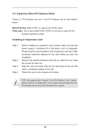
... card is unplugged. Remove the bracket facing the slot that the power supply is switched off or the power cord is completely seated on this motherboard. Step 4.
... card is unplugged. Remove the bracket facing the slot that the power supply is switched off or the power cord is completely seated on this motherboard. Step 4.

User Manual
Page 23
Serial ATA2 Connectors (SATA_0: see p.14, No. 6) SATA_1 (SATA_1: see p.14, No. 2) SATA_0 These two Serial ATA2 (SATA2) connectors support SATA data cables for internal storage devices. The current SATA2 interface allows up to the hard disk. 2.5 Installing Serial SATA / SATA2 Hard Disks STEP 1: Connect the SATA power cable to 3.0 Gb/s data transfer rate. 23 STEP 2: Connect one end of the SATA data cable to the hard disk. STEP 3: Connect the other end of the SATA data cable to the motherboard's SATA2 connectors.
Serial ATA2 Connectors (SATA_0: see p.14, No. 6) SATA_1 (SATA_1: see p.14, No. 2) SATA_0 These two Serial ATA2 (SATA2) connectors support SATA data cables for internal storage devices. The current SATA2 interface allows up to the hard disk. 2.5 Installing Serial SATA / SATA2 Hard Disks STEP 1: Connect the SATA power cable to 3.0 Gb/s data transfer rate. 23 STEP 2: Connect one end of the SATA data cable to the hard disk. STEP 3: Connect the other end of the SATA data cable to the motherboard's SATA2 connectors.

User Manual
Page 26
... Infrared Module Header (7-pin CIR1) (see p.14, No. 7) Besides two default USB 2.0 ports on the I /O panel, there is one USB port on this motherboard. This header can be used to the motherboard! 2.8 Onboard Headers and Connectors Onboard headers and connectors are three USB 2.0 headers and one USB 3.0 header on this... motherboard. USB 2.0 Headers (9-pin USB4_5) (see p.14, No. 20) (9-pin USB6_7) (see p.14, No. 5) Besides two default USB 3.0 ports on the I /O panel, ...
... Infrared Module Header (7-pin CIR1) (see p.14, No. 7) Besides two default USB 2.0 ports on the I /O panel, there is one USB port on this motherboard. This header can be used to the motherboard! 2.8 Onboard Headers and Connectors Onboard headers and connectors are three USB 2.0 headers and one USB 3.0 header on this... motherboard. USB 2.0 Headers (9-pin USB4_5) (see p.14, No. 20) (9-pin USB6_7) (see p.14, No. 5) Besides two default USB 3.0 ports on the I /O panel, ...

User Manual
Page 28
...) Serial Port Header (10-pin COM1) (see p.14, No. 18) Please connect the chassis speaker to this header to indicate system power status. Though this motherboard provides a 4-Pin CPU fan (Quiet Fan) connector, 3-Pin CPU fans can still work even without fan speed control. If you plan to connect a 3-Pin CPU...
...) Serial Port Header (10-pin COM1) (see p.14, No. 18) Please connect the chassis speaker to this header to indicate system power status. Though this motherboard provides a 4-Pin CPU fan (Quiet Fan) connector, 3-Pin CPU fans can still work even without fan speed control. If you plan to connect a 3-Pin CPU...

User Manual
Page 32
...Set IDE Mode in UEFI Setup Utility > Advanced > Storage Configuration > SATA Mode. STEP 1: Set Up UEFI. bit on your system. 2.10 Operating System Setup This motherboard supports various Microsoft® Windows® operating systems: 8 / 8 64-bit / 7 / 7 64-bit / VistaTM / VistaTM 64-bit / XP / XP...documentation for general reference only. Press or at system POST. Using IDE Mode STEP 1: Set Up UEFI. Press or at system POST. Because motherboard settings and hardware options vary, use the setup procedures in this chapter for more information. 2.10.1 Installing Windows® 8 / 8 64-...
...Set IDE Mode in UEFI Setup Utility > Advanced > Storage Configuration > SATA Mode. STEP 1: Set Up UEFI. bit on your system. 2.10 Operating System Setup This motherboard supports various Microsoft® Windows® operating systems: 8 / 8 64-bit / 7 / 7 64-bit / VistaTM / VistaTM 64-bit / XP / XP...documentation for general reference only. Press or at system POST. Using IDE Mode STEP 1: Set Up UEFI. Press or at system POST. Because motherboard settings and hardware options vary, use the setup procedures in this chapter for more information. 2.10.1 Installing Windows® 8 / 8 64-...

User Manual
Page 33
... SP2 or above), 7 64-bit or 8 64-bit and follow the procedures below to be installed on a HDD Larger than 2 terabytes (2TB) without RAID This motherboard adopts UEFI BIOS that allows Windows® OS to install the operating system. STEP 2: Press to launch boot menu at system POST.
... SP2 or above), 7 64-bit or 8 64-bit and follow the procedures below to be installed on a HDD Larger than 2 terabytes (2TB) without RAID This motherboard adopts UEFI BIOS that allows Windows® OS to install the operating system. STEP 2: Press to launch boot menu at system POST.

User Manual
Page 34
... contact your CD-ROM drive. or you install can work properly. 2.11.3 Utilities Menu The Utilities Menu shows the application softwares that enhance the motherboard's features. 2.11.1 Running The Support CD To begin using the support CD, insert the CD into your dealer for further information. 34 Click ...Main Menu if "AUTORUN" is enabled in the Support CD to display the menu. 2.11.2 Drivers Menu The drivers compatible to visit ASRock's website at http://www.asrock.com; If the Main Menu does not appear automatically, locate and double click on the file "ASRSETUP.EXE" in your system will...
... contact your CD-ROM drive. or you install can work properly. 2.11.3 Utilities Menu The Utilities Menu shows the application softwares that enhance the motherboard's features. 2.11.1 Running The Support CD To begin using the support CD, insert the CD into your dealer for further information. 34 Click ...Main Menu if "AUTORUN" is enabled in the Support CD to display the menu. 2.11.2 Drivers Menu The drivers compatible to visit ASRock's website at http://www.asrock.com; If the Main Menu does not appear automatically, locate and double click on the file "ASRSETUP.EXE" in your system will...

User Manual
Page 35
... have already installed the VGA driver from our support CD and restart your computer. DVI-I /O panel and the motherboard. HDMI, DVI and LVDS monitors cannot all be enabled at the same time. This motherboard also provides independent display controllers for HDMI, DVI and LVDS to support dual VGA output so that the... reboots. You can enjoy dual monitor after your system, you haven't installed the VGA driver yet, please install it from our support CD to this motherboard. 2.12 Dual Monitor Dual Monitor This...
... have already installed the VGA driver from our support CD and restart your computer. DVI-I /O panel and the motherboard. HDMI, DVI and LVDS monitors cannot all be enabled at the same time. This motherboard also provides independent display controllers for HDMI, DVI and LVDS to support dual VGA output so that the... reboots. You can enjoy dual monitor after your system, you haven't installed the VGA driver yet, please install it from our support CD to this motherboard. 2.12 Dual Monitor Dual Monitor This...

