
User Manual
Page 4
... 55 3.4.8 ACPI Configuration 56 3.4.9 USB Configuration 57 3.5 Tool 58 3.6 Hardware Health Event Monitoring Screen 60 3.7 Boot Screen 61 3.8 Security Screen 63 3.9 Exit Screen 64 4 Software Support 65 4.1 Install Operating System 65 4.2 Support CD Information 65 4.2.1 Running Support CD 65 4.2.2 Drivers Menu 65 4.2.3 Utilities Menu 65 4.2.4 Contact Information 65 4
... 55 3.4.8 ACPI Configuration 56 3.4.9 USB Configuration 57 3.5 Tool 58 3.6 Hardware Health Event Monitoring Screen 60 3.7 Boot Screen 61 3.8 Security Screen 63 3.9 Exit Screen 64 4 Software Support 65 4.1 Install Operating System 65 4.2 Support CD Information 65 4.2.1 Running Support CD 65 4.2.2 Drivers Menu 65 4.2.3 Utilities Menu 65 4.2.4 Contact Information 65 4
User Manual
Page 5
... information about the model you require technical support related to this manual occur, the updated version will be subject to change without further notice. www.asrock.com/support/index.asp 1.1 Package Contents ASRock H61M-PS4 / H61M-VG4 / H61M-VS4 Motherboard (Micro ATX Form Factor) ASRock H61M-PS4 / H61M-VG4 / H61M-VS4 Quick Installation Guide ASRock H61M-PS4 / H61M-VG4 / H61M-VS4 Support CD 2 x Serial ATA (SATA) Data Cables (Optional...
... information about the model you require technical support related to this manual occur, the updated version will be subject to change without further notice. www.asrock.com/support/index.asp 1.1 Package Contents ASRock H61M-PS4 / H61M-VG4 / H61M-VS4 Motherboard (Micro ATX Form Factor) ASRock H61M-PS4 / H61M-VG4 / H61M-VS4 Quick Installation Guide ASRock H61M-PS4 / H61M-VG4 / H61M-VS4 Support CD 2 x Serial ATA (SATA) Data Cables (Optional...
User Manual
Page 6
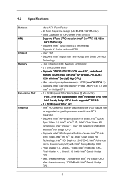
...1066 non-ECC, un-buffered memory (DDR3 1600 with Intel® Ivy Bridge CPU, DDR3 1333 with Intel® Ivy Bridge CPU. Supports 3rd and 2nd Generation Intel® CoreTM i7 / i5 / i3 in Visuals: Intel® Quick Sync Video 2.0, Intel® InTruTM... Sandy Bridge CPU. 6 Max. Supports Intel® Turbo Boost 2.0 Technology - shared memory 1759MB with Intel® Ivy Bridge CPU. Solid Capacitor for CPU power (H61M-VS4) - All Solid Capacitor design (H61M-PS4 / H61M-VG4) - 1.2 Specifications Platform CPU Chipset Memory Expansion Slot Graphics - Supports Intel® HD Graphics Built-in...
...1066 non-ECC, un-buffered memory (DDR3 1600 with Intel® Ivy Bridge CPU, DDR3 1333 with Intel® Ivy Bridge CPU. Supports 3rd and 2nd Generation Intel® CoreTM i7 / i5 / i3 in Visuals: Intel® Quick Sync Video 2.0, Intel® InTruTM... Sandy Bridge CPU. 6 Max. Supports Intel® Turbo Boost 2.0 Technology - shared memory 1759MB with Intel® Ivy Bridge CPU. Solid Capacitor for CPU power (H61M-VS4) - All Solid Capacitor design (H61M-PS4 / H61M-VG4) - 1.2 Specifications Platform CPU Chipset Memory Expansion Slot Graphics - Supports Intel® HD Graphics Built-in...
User Manual
Page 7
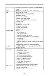
... up to 2048x1536 @ 75Hz - 5.1 CH HD Audio (Realtek ALC662 Audio Codec) H61M-PS4 / H61M-VG4 - Speed: 10/100 Ethernet - HD Audio Jack: Line in/Front Speaker/Microphone - 4 x SATA2 3.0 Gb/s connectors, support NCQ, AHCI and Hot Plug functions - 1 x IR header - 1 x Power LED header - 1 x.../1000 Mb/s - Realtek PCIE x1 LAN 8105E - Supports PXE H61M-VS4 - Supports Wake-On-LAN - Supports Wake-On-LAN - Supports LAN Cable Detection - Supports PXE I /O Storage Connector BIOS Feature - Supports "Plug and Play" - Supports Energy Efficient Ethernet 802.3az - Realtek RTL8111E - Audio...
... up to 2048x1536 @ 75Hz - 5.1 CH HD Audio (Realtek ALC662 Audio Codec) H61M-PS4 / H61M-VG4 - Speed: 10/100 Ethernet - HD Audio Jack: Line in/Front Speaker/Microphone - 4 x SATA2 3.0 Gb/s connectors, support NCQ, AHCI and Hot Plug functions - 1 x IR header - 1 x Power LED header - 1 x.../1000 Mb/s - Realtek PCIE x1 LAN 8105E - Supports PXE H61M-VS4 - Supports Wake-On-LAN - Supports Wake-On-LAN - Supports LAN Cable Detection - Supports PXE I /O Storage Connector BIOS Feature - Supports "Plug and Play" - Supports Energy Efficient Ethernet 802.3az - Realtek RTL8111E - Audio...

User Manual
Page 8
...by overclocking. Voltage Monitoring: +12V, +5V, +3.3V, CPU Vcore OS - CAUTION! 1. CPU/Chassis Fan Multi-Speed Control - Supports jumperfree - Due to the operating system limitation, the actual memory size may affect your system's stability, or even cause damage to utilize...Windows® 8 / 7 / VistaTM / XP. SMBIOS 2.3.1 Support Support CD - FCC, CE, WHQL * For detailed product information, please visit our website: http://www.asrock.com WARNING Please realize that Windows® cannot use ASRock XFast RAM to the components and devices of your own risk and...
...by overclocking. Voltage Monitoring: +12V, +5V, +3.3V, CPU Vcore OS - CAUTION! 1. CPU/Chassis Fan Multi-Speed Control - Supports jumperfree - Due to the operating system limitation, the actual memory size may affect your system's stability, or even cause damage to utilize...Windows® 8 / 7 / VistaTM / XP. SMBIOS 2.3.1 Support Support CD - FCC, CE, WHQL * For detailed product information, please visit our website: http://www.asrock.com WARNING Please realize that Windows® cannot use ASRock XFast RAM to the components and devices of your own risk and...
User Manual
Page 10
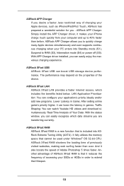
... to extend their lifespan. 10 Another advantage of ASRock XFast RAM is included into Standby mode (S1), Suspend to quickly charge many Apple devices simultaneously and even supports continuous charging when your PC enters into ASRock Extreme Tuning Utility (AXTU). With APP Charger driver... installed, you - ASRock APP Charger allows you to RAM (S3), hibernation mode (S4) or power...
... to extend their lifespan. 10 Another advantage of ASRock XFast RAM is included into Standby mode (S1), Suspend to quickly charge many Apple devices simultaneously and even supports continuous charging when your PC enters into ASRock Extreme Tuning Utility (AXTU). With APP Charger driver... installed, you - ASRock APP Charger allows you to RAM (S3), hibernation mode (S4) or power...
User Manual
Page 11
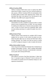
...Please note that BIOS files need to be running on automatically to dehumidify the system after regaining power. No more waiting! ASRock Dehumidifier Function Users may schedule the starting and ending hours of internet access granted to other words, the system can autodetect... after entering S4/S5 state. In other users. ASRock Crashless BIOS ASRock Crashless BIOS allows users to update their BIOS without entering Windows® OS. ASRock OMG (Online Management Guard) Administrators are required. Only USB2.0 ports support this function. In order to prevent users from our...
...Please note that BIOS files need to be running on automatically to dehumidify the system after regaining power. No more waiting! ASRock Dehumidifier Function Users may schedule the starting and ending hours of internet access granted to other words, the system can autodetect... after entering S4/S5 state. In other users. ASRock Crashless BIOS ASRock Crashless BIOS allows users to update their BIOS without entering Windows® OS. ASRock OMG (Online Management Guard) Administrators are required. Only USB2.0 ports support this function. In order to prevent users from our...

User Manual
Page 18
... CPU with load plate tab under retention tab of load lever. Step 4-3. Secure load lever with IHS (Integrated Heat Sink) up. Verify that this motherboard supports Combo Cooler Option (C.C.O.), which provides the flexible option to the orient keys. Step 3-3. orientation key notch alignment key Pin1 Pin1 orientation key notch 1155-Pin...
... CPU with load plate tab under retention tab of load lever. Step 4-3. Secure load lever with IHS (Integrated Heat Sink) up. Verify that this motherboard supports Combo Cooler Option (C.C.O.), which provides the flexible option to the orient keys. Step 3-3. orientation key notch alignment key Pin1 Pin1 orientation key notch 1155-Pin...

User Manual
Page 19
... (CPU_FAN1, see page 13, No. 2). Before you installed the heatsink, you press down on fastener caps with fan operation or contact other . Step 1. Ensure that supports Intel 1155-Pin CPU. Apply thermal interface material onto center of your CPU fan and heatsink. 2.4 Installation of CPU Fan and Heatsink This motherboard is...
... (CPU_FAN1, see page 13, No. 2). Before you installed the heatsink, you press down on fastener caps with fan operation or contact other . Step 1. Ensure that supports Intel 1155-Pin CPU. Apply thermal interface material onto center of your CPU fan and heatsink. 2.4 Installation of CPU Fan and Heatsink This motherboard is...

User Manual
Page 20
... to activate the Dual Channel Memory Technology. 3. 2.5 Installation of Memory Modules (DIMM) This motherboard provides two 240-pin DDR3 (Double Data Rate 3) DIMM slots, and supports Dual Channel Memory Technology.
... to activate the Dual Channel Memory Technology. 3. 2.5 Installation of Memory Modules (DIMM) This motherboard provides two 240-pin DDR3 (Double Data Rate 3) DIMM slots, and supports Dual Channel Memory Technology.

User Manual
Page 21
... for later use . Align the card connector with screws. 2.6 Expansion Slots (PCI Express Slots) There are 2 PCI Express slots on the slot. Only PCIE1 slot supports Gen 3 speed. Step 3. Step 5. Fasten the card to use . Keep the screws for PCI Express x1 lane width cards. Please read the documentation of the...
... for later use . Align the card connector with screws. 2.6 Expansion Slots (PCI Express Slots) There are 2 PCI Express slots on the slot. Only PCIE1 slot supports Gen 3 speed. Step 3. Step 5. Fasten the card to use . Keep the screws for PCI Express x1 lane width cards. Please read the documentation of the...

User Manual
Page 23
... connectors. Do NOT place jumper caps over the headers and connectors will cause permanent damage of the SATA data cable can support two USB 2.0 ports. Infrared Module Header (5-pin IR1) (see p.13, No. 8) SATA_3 SATA_2 SATA_1 SATA_1 These four Serial ATA2 (SATA2) ... p.13, No. 7) (SATA_1: see p.13, No. 6) (SATA_2: see p.13, No. 9) (SATA_3: see p.13 No. 17) IRTX +5VSB DUMMY 1 GND IRRX This header supports an optional wireless transmitting and receiving infrared module. 23 The current SATA2 interface allows up to the SATA / SATA2 hard disk or the SATA2 connector...
... connectors. Do NOT place jumper caps over the headers and connectors will cause permanent damage of the SATA data cable can support two USB 2.0 ports. Infrared Module Header (5-pin IR1) (see p.13, No. 8) SATA_3 SATA_2 SATA_1 SATA_1 These four Serial ATA2 (SATA2) ... p.13, No. 7) (SATA_1: see p.13, No. 6) (SATA_2: see p.13, No. 9) (SATA_3: see p.13 No. 17) IRTX +5VSB DUMMY 1 GND IRRX This header supports an optional wireless transmitting and receiving infrared module. 23 The current SATA2 interface allows up to the SATA / SATA2 hard disk or the SATA2 connector...

User Manual
Page 24
High Definition Audio supports Jack Sensing, but the panel wire on the chassis front panel. If you use AC'97 audio panel, please install it to the front panel ... as below . MIC_RET and OUT_RET are for AC'97 audio panel. Select "Recorder". RESET (Reset Switch): Connect to the reset switch on the chassis must support HDA to the pin assignments below : A. The LED 24 B. PWRBTN (Power Switch): Connect to the power switch on the chassis to this header according to...
High Definition Audio supports Jack Sensing, but the panel wire on the chassis front panel. If you use AC'97 audio panel, please install it to the front panel ... as below . MIC_RET and OUT_RET are for AC'97 audio panel. Select "Recorder". RESET (Reset Switch): Connect to the reset switch on the chassis must support HDA to the pin assignments below : A. The LED 24 B. PWRBTN (Power Switch): Connect to the power switch on the chassis to this header according to...

User Manual
Page 25
... on when the hard drive is operating. Pin 1-3 Connected 3-Pin Fan Installation 25 The LED is on this motherboard provides 4-Pin CPU fan (Quiet Fan) support, the 3-Pin CPU fan still can work successfully even without the fan speed control function. The LED keeps blinking in S1 sleep state. The front...
... on when the hard drive is operating. Pin 1-3 Connected 3-Pin Fan Installation 25 The LED is on this motherboard provides 4-Pin CPU fan (Quiet Fan) support, the 3-Pin CPU fan still can work successfully even without the fan speed control function. The LED keeps blinking in S1 sleep state. The front...

User Manual
Page 26
... chassis intrusion detection design. This feature requires a chassis with a cable. 26 ATX 12V Power Connector (4-pin ATX12V1) (see p.13, No. 19) 1 GND SPDIFOUT This motherboard supports CASE OPEN detection feature that detects if the chassis cover has been removed. Chassis Intrusion Header (2-pin CI1) (see p.13, No. 15) 1 GND Signal SPDIF...
... chassis intrusion detection design. This feature requires a chassis with a cable. 26 ATX 12V Power Connector (4-pin ATX12V1) (see p.13, No. 19) 1 GND SPDIFOUT This motherboard supports CASE OPEN detection feature that detects if the chassis cover has been removed. Chassis Intrusion Header (2-pin CI1) (see p.13, No. 15) 1 GND Signal SPDIF...

User Manual
Page 27
PIN Signal Name 14 +3V 12 +3V 10 GND 8 LAD3 6 LAD1 4 LFRAME# 2 GND PIN Signal Name 13 No pin 11 +3V 9 GND 7 LAD2 5 LAD0 3 RESET# 1 CLK 27 LPC/TPM Header (13-pin LPC/TPM1) (see p.13, No. 16 1 This connector supports Trusted Platform Module (TPM) system, which can securely store keys, digital certificates, passwords, and data. A TPM system also helps enhance network security, protects digital identities, and ensures platform integrity.
PIN Signal Name 14 +3V 12 +3V 10 GND 8 LAD3 6 LAD1 4 LFRAME# 2 GND PIN Signal Name 13 No pin 11 +3V 9 GND 7 LAD2 5 LAD0 3 RESET# 1 CLK 27 LPC/TPM Header (13-pin LPC/TPM1) (see p.13, No. 16 1 This connector supports Trusted Platform Module (TPM) system, which can securely store keys, digital certificates, passwords, and data. A TPM system also helps enhance network security, protects digital identities, and ensures platform integrity.
User Manual
Page 28
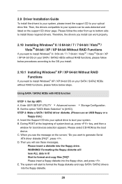
2.9 Driver Installation Guide To install the drivers to your system, please insert the support CD to your system can work properly. 2.10 Installing Windows® 8 / 8 64-bit / 7 / 7 64-bit / VistaTM / VistaTM 64-bit / XP / XP 64-bit Without RAID ... to boot your SATA / SATA2 HDDs without RAID functions, please follow below procedures according to install Windows® XP / XP 64-bit OS on the support CD driver page. A. STEP 2: Make a SATA / SATA2 driver diskette. (Please use an USB floppy or a floppy disk.) A. When you want to format the floppy diskette...
2.9 Driver Installation Guide To install the drivers to your system, please insert the support CD to your system can work properly. 2.10 Installing Windows® 8 / 8 64-bit / 7 / 7 64-bit / VistaTM / VistaTM 64-bit / XP / XP 64-bit Without RAID ... to boot your SATA / SATA2 HDDs without RAID functions, please follow below procedures according to install Windows® XP / XP 64-bit OS on the support CD driver page. A. STEP 2: Make a SATA / SATA2 driver diskette. (Please use an USB floppy or a floppy disk.) A. When you want to format the floppy diskette...
User Manual
Page 43
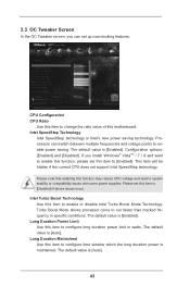
... ratio value of this item to configure long duration power limit in specific conditions. This item will be hidden if the current CPU does not support Intel SpeedStep technology. Please set up overclocking features. Long Duration Power Limit Use this item to [Disabled] if above issues occur.
... ratio value of this item to configure long duration power limit in specific conditions. This item will be hidden if the current CPU does not support Intel SpeedStep technology. Please set up overclocking features. Long Duration Power Limit Use this item to [Disabled] if above issues occur.
User Manual
Page 44
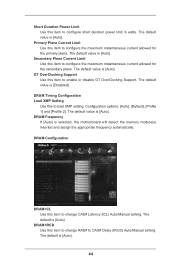
...configure the maximum instantaneous current allowed for the secondary plane. DRAM Timing Configuration Load XMP Setting Use this item to enable or disable GT OverClocking Support. Configuration options: [Auto], [Default], [Profile 1] and [Profile 2]. The default value is [Auto]. The default value is [Auto]. The... Latency (tCL) Auto/Manual setting. The default value is [Auto]. 44 DRAM Frequency If [Auto] is [Auto]. GT OverClocking Support Use this item to change RAS# to configure short duration power limit in watts. The default value is selected, the motherboard will detect...
...configure the maximum instantaneous current allowed for the secondary plane. DRAM Timing Configuration Load XMP Setting Use this item to enable or disable GT OverClocking Support. Configuration options: [Auto], [Default], [Profile 1] and [Profile 2]. The default value is [Auto]. The default value is [Auto]. The... Latency (tCL) Auto/Manual setting. The default value is [Auto]. 44 DRAM Frequency If [Auto] is [Auto]. GT OverClocking Support Use this item to change RAS# to configure short duration power limit in watts. The default value is selected, the motherboard will detect...

User Manual
Page 48
... select [Enabled] to enable CPU internal thermal control mechanism to keep the CPU from the chipset. Enhance Halt State (C1E) All processors support the Halt State (C1). CPU C6 State Support Use this to enable or disable CPU C3 (ACPI C2) report to OS. The default value is...(NX) Memory Protection Technology is [All]. 3.4.1 CPU Configuration Intel Hyper Threading Technology To enable this feature, a computer system with an Intel processor that supports Hyper-Threading technology and an operating system that includes optimization for this item to select the number of the system caches.
... select [Enabled] to enable CPU internal thermal control mechanism to keep the CPU from the chipset. Enhance Halt State (C1E) All processors support the Halt State (C1). CPU C6 State Support Use this to enable or disable CPU C3 (ACPI C2) report to OS. The default value is...(NX) Memory Protection Technology is [All]. 3.4.1 CPU Configuration Intel Hyper Threading Technology To enable this feature, a computer system with an Intel processor that supports Hyper-Threading technology and an operating system that includes optimization for this item to select the number of the system caches.


