
User Manual
Page 13
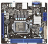
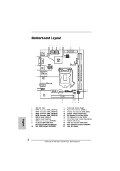
1.3 Motherboard Layout (H61M-VG3 / H61M-VS3) 12 3 4 5 67 8 9 DDR3 Fast RAM X DDR3_A1 (64 bit, 240-pin module) DDR3_B1 (64 bit, 240-pin module) SATA_0 (PORT 0) SATA_2 (PORT 4) PS2 Mouse PS2 ... Intrusion Header (CI1) 15 PCI Express 3.0 x16 Slot (PCIE2) 16 PCI Express 2.0 x1 Slot (PCIE1) 17 Front Panel Audio Header (HD_AUDIO1) 18 1155-Pin CPU Socket 19 CPU Fan Connector (CPU_FAN1) 20 ATX 12V Power Connector (ATX12V1) 21 Intel H61 Chipset 13
1.3 Motherboard Layout (H61M-VG3 / H61M-VS3) 12 3 4 5 67 8 9 DDR3 Fast RAM X DDR3_A1 (64 bit, 240-pin module) DDR3_B1 (64 bit, 240-pin module) SATA_0 (PORT 0) SATA_2 (PORT 4) PS2 Mouse PS2 ... Intrusion Header (CI1) 15 PCI Express 3.0 x16 Slot (PCIE2) 16 PCI Express 2.0 x1 Slot (PCIE1) 17 Front Panel Audio Header (HD_AUDIO1) 18 1155-Pin CPU Socket 19 CPU Fan Connector (CPU_FAN1) 20 ATX 12V Power Connector (ATX12V1) 21 Intel H61 Chipset 13

User Manual
Page 16
... static electricity, NEVER place your chassis to unplug the power cord before installing or removing the motherboard. Chapter 2: Installation This is detached from the wall socket before touching any motherboard settings. 1. To avoid damaging the motherboard components due to the motherboard, peripherals, and/or components. 16 Make sure to ensure that...
... static electricity, NEVER place your chassis to unplug the power cord before installing or removing the motherboard. Chapter 2: Installation This is detached from the wall socket before touching any motherboard settings. 1. To avoid damaging the motherboard components due to the motherboard, peripherals, and/or components. 16 Make sure to ensure that...

User Manual
Page 17
... to handle and avoid kicking off the PnP cap. 2. This cap must be seriously damaged. Rotate the load plate to insert the CPU into the socket, please check if the CPU surface is unclean or if there is recommended to use the cap tab to clear retention tab. Open the... socket: Step 1-1. Do not force to fully open position at approximately 100 degrees. Remove PnP Cap (Pick and Place Cap). 1. 2.3 CPU Installation For the installation of ...
... to handle and avoid kicking off the PnP cap. 2. This cap must be seriously damaged. Rotate the load plate to insert the CPU into the socket, please check if the CPU surface is unclean or if there is recommended to use the cap tab to clear retention tab. Open the... socket: Step 1-1. Do not force to fully open position at approximately 100 degrees. Remove PnP Cap (Pick and Place Cap). 1. 2.3 CPU Installation For the installation of ...

User Manual
Page 18
...is marked with IHS (Integrated Heat Sink) up. Hold the CPU by using a purely vertical motion. black line Step 3-2. Step 3-4. Step 4-2. Close the socket: Step 4-1. Step 3-3. Locate Pin1 and the two orientation key notches. Step 3. Rotate the load plate onto the IHS. Step 4. orientation key notch alignment... key Pin1 Pin1 orientation key notch 1155-Pin CPU alignment key 1155-Pin Socket For proper inserting, please ensure to the orient keys. While pressing down lightly on load plate, engage the load lever. 18
...is marked with IHS (Integrated Heat Sink) up. Hold the CPU by using a purely vertical motion. black line Step 3-2. Step 3-4. Step 4-2. Close the socket: Step 4-1. Step 3-3. Locate Pin1 and the two orientation key notches. Step 3. Rotate the load plate onto the IHS. Step 4. orientation key notch alignment... key Pin1 Pin1 orientation key notch 1155-Pin CPU alignment key 1155-Pin Socket For proper inserting, please ensure to the orient keys. While pressing down lightly on load plate, engage the load lever. 18

User Manual
Page 19
...of IHS on the motherboard (CPU_ FAN1, see page 13, No. 19). Then connect the CPU fan to the CPU fan connector on the socket surface. Apply thermal interface material onto center of heatsink and cooling fan compliant with fan operation or contact other . Align fasteners with remaining fasteners....(4 Places) If you need to spray thermal interface material between the CPU and the heatsink to dissipate heat. Below is equipped with 1155-Pin socket that the CPU and the heatsink are oriented on side closest to the CPU_FAN connector (CPU_FAN1, see page 13, No. 19). Place the ...
...of IHS on the motherboard (CPU_ FAN1, see page 13, No. 19). Then connect the CPU fan to the CPU fan connector on the socket surface. Apply thermal interface material onto center of heatsink and cooling fan compliant with fan operation or contact other . Align fasteners with remaining fasteners....(4 Places) If you need to spray thermal interface material between the CPU and the heatsink to dissipate heat. Below is equipped with 1155-Pin socket that the CPU and the heatsink are oriented on side closest to the CPU_FAN connector (CPU_FAN1, see page 13, No. 19). Place the ...
Quick Installation Guide
Page 2
... Intrusion Header (CI1) 15 PCI Express 3.0 x16 Slot (PCIE2) 16 PCI Express 2.0 x1 Slot (PCIE1) 17 Front Panel Audio Header (HD_AUDIO1) 18 1155-Pin CPU Socket 19 CPU Fan Connector (CPU_FAN1) 20 ATX 12V Power Connector (ATX12V1) 21 Intel H61 Chipset English 2 ASRock H61M-VG3 / H61M-VS3 Motherboard
... Intrusion Header (CI1) 15 PCI Express 3.0 x16 Slot (PCIE2) 16 PCI Express 2.0 x1 Slot (PCIE1) 17 Front Panel Audio Header (HD_AUDIO1) 18 1155-Pin CPU Socket 19 CPU Fan Connector (CPU_FAN1) 20 ATX 12V Power Connector (ATX12V1) 21 Intel H61 Chipset English 2 ASRock H61M-VG3 / H61M-VS3 Motherboard