
User Manual
Page 11
EuP, stands for Energy Using Product, was a provision regulated by European Union to adopt three different CPU cooler types, Socket LGA 775, LGA 1155 and LGA 1156. For EuP ready power supply selection, we recommend you checking with the power supply manufacturer for the completed system. According to Intel's ...
EuP, stands for Energy Using Product, was a provision regulated by European Union to adopt three different CPU cooler types, Socket LGA 775, LGA 1155 and LGA 1156. For EuP ready power supply selection, we recommend you checking with the power supply manufacturer for the completed system. According to Intel's ...
User Manual
Page 12
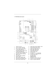
...IN Center: FRONT PWR_FAN1 VGA1 HDMI1 Bottom: Optical SPDIF Bottom: MIC IN 7 CHA_FAN2 30 29 28 27 26 25 24 HD_AUDIO1 1 LAN PHY CHA_FAN3 8 H61DE/SI PCIE1 RoHS CMOS Battery PCI Express 2.0 ErP/EuP Ready 1 HDMI_SPDIF_1 PCIE2 AUDIO CODEC Intel H61 PCI1 1 USB8_9 32Mb BIOS 9 CLRCMOS1 1 10 11 12 ... PWRBTN IR1 SPEAKER1 1 HDLED RESET 1 1 PANEL1 14 22 21 20 19 18 17 16 15 1 2 3 4 5 6 7 8 9 10 11 12 13 14 15 1155-Pin CPU Socket CPU Fan Connector (CPU_FAN1) CPU Fan Connector (CPU_FAN2) ATX 12V Power Connector (ATX12V1) 2 x 240-pin DDR3 DIMM Slots (Dual Channel: DDR3_A1, DDR3_B1...
...IN Center: FRONT PWR_FAN1 VGA1 HDMI1 Bottom: Optical SPDIF Bottom: MIC IN 7 CHA_FAN2 30 29 28 27 26 25 24 HD_AUDIO1 1 LAN PHY CHA_FAN3 8 H61DE/SI PCIE1 RoHS CMOS Battery PCI Express 2.0 ErP/EuP Ready 1 HDMI_SPDIF_1 PCIE2 AUDIO CODEC Intel H61 PCI1 1 USB8_9 32Mb BIOS 9 CLRCMOS1 1 10 11 12 ... PWRBTN IR1 SPEAKER1 1 HDLED RESET 1 1 PANEL1 14 22 21 20 19 18 17 16 15 1 2 3 4 5 6 7 8 9 10 11 12 13 14 15 1155-Pin CPU Socket CPU Fan Connector (CPU_FAN1) CPU Fan Connector (CPU_FAN2) ATX 12V Power Connector (ATX12V1) 2 x 240-pin DDR3 DIMM Slots (Dual Channel: DDR3_A1, DDR3_B1...
User Manual
Page 16
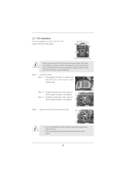
... degrees. It is recommended to use the cap tab to clear retention tab. Load Plate Load Lever Contact Array Socket Body 1155-Pin Socket Overview Before you insert the 1155-Pin CPU into the socket if above situation is any bent pin on the hook to handle and avoid kicking off the... or if there is found. Disengaging the lever by depressing down and out on the socket. Step 1-3. Step 2. 2.3 CPU Installation For the installation of Intel 1155-Pin CPU, please follow the steps below. Do not force to fully open position at approximately 100 degrees.
... degrees. It is recommended to use the cap tab to clear retention tab. Load Plate Load Lever Contact Array Socket Body 1155-Pin Socket Overview Before you insert the 1155-Pin CPU into the socket if above situation is any bent pin on the hook to handle and avoid kicking off the... or if there is found. Disengaging the lever by depressing down and out on the socket. Step 1-3. Step 2. 2.3 CPU Installation For the installation of Intel 1155-Pin CPU, please follow the steps below. Do not force to fully open position at approximately 100 degrees.
User Manual
Page 17
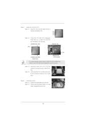
..., engage the load lever. 17 Hold the CPU by using a purely vertical motion. orientation key notch Pin1 alignment key Pin1 alignment key orientation key notch 1155-Pin CPU 1155-Pin Socket For proper inserting, please ensure to the orient keys. Step 3-4. Insert the...
..., engage the load lever. 17 Hold the CPU by using a purely vertical motion. orientation key notch Pin1 alignment key Pin1 alignment key orientation key notch 1155-Pin CPU 1155-Pin Socket For proper inserting, please ensure to the orient keys. Step 3-4. Insert the...
User Manual
Page 18
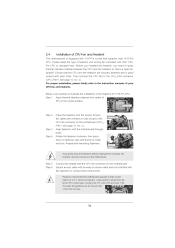
... Place the heatsink onto the socket. Ensure fan cables are oriented on side closest to illustrate the installation of the heatsink for Socket LGA 1155/1156 CPU fan. 18 Fan cables on side closest to improve heat dissipation. Step 6. Before you installed the heatsink, you need to spray...pointing straight out Press Down (4 Places) If you press down on fastener caps with thumb to ensure cable does not interfere with 1155-Pin socket that supports Intel 1155-Pin CPU. For proper installation, please kindly refer to the CPU_FAN connector (CPU_FAN1, see page 12, No. 2). Step 4....
... Place the heatsink onto the socket. Ensure fan cables are oriented on side closest to illustrate the installation of the heatsink for Socket LGA 1155/1156 CPU fan. 18 Fan cables on side closest to improve heat dissipation. Step 6. Before you installed the heatsink, you need to spray...pointing straight out Press Down (4 Places) If you press down on fastener caps with thumb to ensure cable does not interfere with 1155-Pin socket that supports Intel 1155-Pin CPU. For proper installation, please kindly refer to the CPU_FAN connector (CPU_FAN1, see page 12, No. 2). Step 4....

Quick Installation Guide
Page 2
... 1 USB8_9 1 CHA_FAN1 SATA2_0 SATA2_2 SATA2_1 SATA2_3 SPEAKER1 1 PLED PWRBTN 1 HDLED RESET PANEL1 22 21 20 19 18 17 16 15 8 9 10 11 12 13 14 1 1155-Pin CPU Socket 2 CPU Fan Connector (CPU_FAN1) 3 CPU Fan Connector (CPU_FAN2) 4 ATX 12V Power Connector (ATX12V1) 5 2 x 240-pin DDR3 DIMM Slots (Dual Channel: DDR3_A1, DDR3_B1... Header (HD_AUDIO1, White) 27 HDMI_SPDIF Header (HDMI_SPDIF1, White) 28 PCI Express 2.0 x16 Slot (PCIE1, Blue) 29 Chassis Fan Connector (CHA_FAN3) 30 Power Fan Connector (PWR_FAN1) 2 ASRock H61DE/SI Motherboard English
... 1 USB8_9 1 CHA_FAN1 SATA2_0 SATA2_2 SATA2_1 SATA2_3 SPEAKER1 1 PLED PWRBTN 1 HDLED RESET PANEL1 22 21 20 19 18 17 16 15 8 9 10 11 12 13 14 1 1155-Pin CPU Socket 2 CPU Fan Connector (CPU_FAN1) 3 CPU Fan Connector (CPU_FAN2) 4 ATX 12V Power Connector (ATX12V1) 5 2 x 240-pin DDR3 DIMM Slots (Dual Channel: DDR3_A1, DDR3_B1... Header (HD_AUDIO1, White) 27 HDMI_SPDIF Header (HDMI_SPDIF1, White) 28 PCI Express 2.0 x16 Slot (PCIE1, Blue) 29 Chassis Fan Connector (CHA_FAN3) 30 Power Fan Connector (PWR_FAN1) 2 ASRock H61DE/SI Motherboard English

Quick Installation Guide
Page 10
... supply manufacturer for the completed system. According to define the power consumption for more details. 10 ASRock H61DE/SI Motherboard English According to adopt three different CPU cooler types, Socket LGA 775, LGA 1155 and LGA 1156. To meet the standard of the completed system shall be used. 16. 15. Please be...
... supply manufacturer for the completed system. According to define the power consumption for more details. 10 ASRock H61DE/SI Motherboard English According to adopt three different CPU cooler types, Socket LGA 775, LGA 1155 and LGA 1156. To meet the standard of the completed system shall be used. 16. 15. Please be...
Quick Installation Guide
Page 11
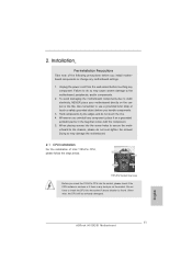
...NEVER place your motherboard directly on the socket. Do not force to the chassis, please do not touch the ICs. 4. English 11 ASRock H61DE/SI Motherboard erboard to insert the CPU into the socket, please check if the CPU surface is unclean or if there is found. Hold ...edges and do not over-tighten the screws! Otherwise, the CPU will be seriously damaged. Installation Pre-installation Precautions Take note of Intel 1155-Pin CPU, please follow the steps below. Failure to use a grounded wrist strap or touch a safety grounded object before touching any bent...
...NEVER place your motherboard directly on the socket. Do not force to the chassis, please do not touch the ICs. 4. English 11 ASRock H61DE/SI Motherboard erboard to insert the CPU into the socket, please check if the CPU surface is unclean or if there is found. Hold ...edges and do not over-tighten the screws! Otherwise, the CPU will be seriously damaged. Installation Pre-installation Precautions Take note of Intel 1155-Pin CPU, please follow the steps below. Failure to use a grounded wrist strap or touch a safety grounded object before touching any bent...

Quick Installation Guide
Page 12
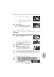
...two alignment keys of the CPU with IHS (Integrated Heat Sink) up. Insert the 1155-Pin CPU: Step 3-1. orientation key notch alignment key Pin1 Pin1 orientation key notch 1155-Pin CPU alignment key 1155-Pin Socket For proper inserting, please ensure to fully open position at approximately 100 degrees...are marked with black lines. Step 1-3. Step 1. Rotate the load plate to match the two orientation key notches of the socket. 12 ASRock H61DE/SI Motherboard It is recommended to use the cap tab to clear retention tab. Hold the CPU by depressing down and out on the hook...
...two alignment keys of the CPU with IHS (Integrated Heat Sink) up. Insert the 1155-Pin CPU: Step 3-1. orientation key notch alignment key Pin1 Pin1 orientation key notch 1155-Pin CPU alignment key 1155-Pin Socket For proper inserting, please ensure to fully open position at approximately 100 degrees...are marked with black lines. Step 1-3. Step 1. Rotate the load plate to match the two orientation key notches of the socket. 12 ASRock H61DE/SI Motherboard It is recommended to use the cap tab to clear retention tab. Hold the CPU by depressing down and out on the hook...
Quick Installation Guide
Page 13
... down on load plate, engage the load lever. 2.2 Installation of IHS on the motherboard. Step 4. Step 4. Ensure fan cables are for 1155-Pin CPU. Step 6. Secure excess cable with tie-wrap to the CPU fan connector on side closest to ensure cable does not interfere with ... supports Combo Cooler Option (C.C.O.), which provides the flexible option to the instruction manuals of the heatsink for Socket LGA 1155/1156 CPU fan. 13 ASRock H61DE/SI Motherboard English Rotate the load plate onto the IHS. Carefully place the CPU into the socket by using a purely vertical motion...
... down on load plate, engage the load lever. 2.2 Installation of IHS on the motherboard. Step 4. Step 4. Ensure fan cables are for 1155-Pin CPU. Step 6. Secure excess cable with tie-wrap to the CPU fan connector on side closest to ensure cable does not interfere with ... supports Combo Cooler Option (C.C.O.), which provides the flexible option to the instruction manuals of the heatsink for Socket LGA 1155/1156 CPU fan. 13 ASRock H61DE/SI Motherboard English Rotate the load plate onto the IHS. Carefully place the CPU into the socket by using a purely vertical motion...