User Manual
Page 7
... GHz Antennas 9 Chapter 2 Installation 11 2.1 Installing the CPU 12 2.2 Installing the CPU Fan and Heatsink 14 2.3 Installing Memory Modules (DIMM) 15 2.4 Expansion Slots (PCI Express Slots) 17 2.5 Jumpers Setup 18 2.6 Onboard Headers and Connectors 19 2.7 M.2_SSD (NGFF) Module Installation Guide (M2_2) 24 Chapter 3 Software and Utilities Operation 28 3.1 Installing Drivers 28 3.2 ASRock Motherboard Utility (A-Tuning) 29 3.2.1 Installing ASRock Motherboard Utility (A-Tuning) 29 3.2.2 Using ASRock Motherboard Utility (A-Tuning) 29 3.3 ASRock Live Update & APP Shop 32...
... GHz Antennas 9 Chapter 2 Installation 11 2.1 Installing the CPU 12 2.2 Installing the CPU Fan and Heatsink 14 2.3 Installing Memory Modules (DIMM) 15 2.4 Expansion Slots (PCI Express Slots) 17 2.5 Jumpers Setup 18 2.6 Onboard Headers and Connectors 19 2.7 M.2_SSD (NGFF) Module Installation Guide (M2_2) 24 Chapter 3 Software and Utilities Operation 28 3.1 Installing Drivers 28 3.2 ASRock Motherboard Utility (A-Tuning) 29 3.2.1 Installing ASRock Motherboard Utility (A-Tuning) 29 3.2.2 Using ASRock Motherboard Utility (A-Tuning) 29 3.3 ASRock Live Update & APP Shop 32...
User Manual
Page 9
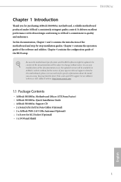
Because the motherboard specifications and the BIOS software might be updated, the content of this documentation will be subject to change without further notice. You may find the latest VGA cards and CPU support list on ASRock's website without notice. ASRock website http://www.asrock.com. 1.1 Package Contents • ASRock H610M/ac Motherboard (Micro ATX Form Factor) • ASRock H610M/ac Quick Installation Guide • ASRock H610M/ac Support CD • 2 x Serial ATA (SATA) Data Cables (Optional) • 2 x ASRock WiFi 2.4/5 GHz Antennas (Optional) • 1 x Screw...
Because the motherboard specifications and the BIOS software might be updated, the content of this documentation will be subject to change without further notice. You may find the latest VGA cards and CPU support list on ASRock's website without notice. ASRock website http://www.asrock.com. 1.1 Package Contents • ASRock H610M/ac Motherboard (Micro ATX Form Factor) • ASRock H610M/ac Quick Installation Guide • ASRock H610M/ac Support CD • 2 x Serial ATA (SATA) Data Cables (Optional) • 2 x ASRock WiFi 2.4/5 GHz Antennas (Optional) • 1 x Screw...
User Manual
Page 10
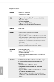
... the VGA outputs can be supported only with processors which are GPU integrated. • Intel® Xe Graphics Architecture (Gen 12) • Three graphics output options: D-Sub, HDMI and DisplayPort 1.4 • Supports HDMI 2.1 TMDS Compatible with DSC (compressed) max. ECC mode) • Max. capacity of system memory: 64GB • Supports Intel® Extreme Memory Profile (XMP) 2.0 Expansion Slot • 1 x PCIe Gen4x16 Slot* * Supports NVMe SSD as boot disks • 2 x PCIe Gen3x1 Slots • 1 x M.2 Socket (Key E), supports type 2230...
... the VGA outputs can be supported only with processors which are GPU integrated. • Intel® Xe Graphics Architecture (Gen 12) • Three graphics output options: D-Sub, HDMI and DisplayPort 1.4 • Supports HDMI 2.1 TMDS Compatible with DSC (compressed) max. ECC mode) • Max. capacity of system memory: 64GB • Supports Intel® Extreme Memory Profile (XMP) 2.0 Expansion Slot • 1 x PCIe Gen4x16 Slot* * Supports NVMe SSD as boot disks • 2 x PCIe Gen3x1 Slots • 1 x M.2 Socket (Key E), supports type 2230...
User Manual
Page 11
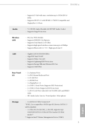
H610M/ac • Supports D-Sub with LED (ACT/LINK LED and SPEED LED) • HD Audio Jacks: Line in / Front Speaker / Microphone Storage • 4 x SATA3 6.0 Gb/s Connectors* * If M2_2 is occupied by a SATA-type M.2 device, SATA3_3 will be disabled. • 1 x Ultra M.2 Socket (M2_2, Key M), supports type 2260/2280 SATA3 6.0 Gb/s & PCIe Gen3x4 (32 Gb/s) modes** ** Supports Intel® Volume Management Device (VMD) 3 English resolution up to 1920x1200 @ 60Hz • Supports HDCP 2.3 with HDMI 2.1 TMDS Compatible and DisplayPort...
H610M/ac • Supports D-Sub with LED (ACT/LINK LED and SPEED LED) • HD Audio Jacks: Line in / Front Speaker / Microphone Storage • 4 x SATA3 6.0 Gb/s Connectors* * If M2_2 is occupied by a SATA-type M.2 device, SATA3_3 will be disabled. • 1 x Ultra M.2 Socket (M2_2, Key M), supports type 2260/2280 SATA3 6.0 Gb/s & PCIe Gen3x4 (32 Gb/s) modes** ** Supports Intel® Volume Management Device (VMD) 3 English resolution up to 1920x1200 @ 60Hz • Supports HDCP 2.3 with HDMI 2.1 TMDS Compatible and DisplayPort...
User Manual
Page 12
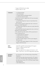
...ATX Power Connector • 1 x 8 pin 12V Power Connector • 1 x Front Panel Audio Connector • 2 x USB 2.0 Headers (Support 3 USB 2.0 ports) (Supports ESD Protection) • 1 x USB 3.2 Gen1 Header (Supports 2 USB 3.2 Gen1 ports) (Supports ESD Protection) BIOS Feature • AMI UEFI Legal BIOS with multilingual GUI support • ACPI 6.0 Compliant wake up events • SMBIOS 2.7 Support • CPU Core/Cache, CPU GT, DRAM, VCCIN AUX, +1.05V PROC, +0.82V PCH, +1.05V PCH Voltage Multi-adjustment English Hardware Monitor • Fan Tachometer: CPU, CPU/Water Pump, Chassis...
...ATX Power Connector • 1 x 8 pin 12V Power Connector • 1 x Front Panel Audio Connector • 2 x USB 2.0 Headers (Support 3 USB 2.0 ports) (Supports ESD Protection) • 1 x USB 3.2 Gen1 Header (Supports 2 USB 3.2 Gen1 ports) (Supports ESD Protection) BIOS Feature • AMI UEFI Legal BIOS with multilingual GUI support • ACPI 6.0 Compliant wake up events • SMBIOS 2.7 Support • CPU Core/Cache, CPU GT, DRAM, VCCIN AUX, +1.05V PROC, +0.82V PCH, +1.05V PCH Voltage Multi-adjustment English Hardware Monitor • Fan Tachometer: CPU, CPU/Water Pump, Chassis...
User Manual
Page 15
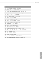
...Connector (ATX12V1) 2 CPU Fan Connector (CPU_FAN1) 3 2 x 288-pin DDR4 DIMM Slots (DDR4_A1, DDR4_B1) 4 Chassis/Water Pump Fan Connector (CHA_FAN1/WP) 5 ATX Power Connector (ATXPWR1) 6 USB 3.2 Gen1 Header (F_USB3_1_2) 7 SATA3 Connector (SATA3_1) 8 SATA3 Connector (SATA3_0) 9 SATA3 Connector (SATA3_2)(Upper) 10 SATA3 Connector (SATA3_3)(Lower) 11 SPI TPM Header (SPI_TPM_J1) 12 System Panel Header (PANEL1) 13 Clear CMOS Jumper (CLRMOS1) 14 Chassis Intrusion and Speaker Header (SPK_CI1) 15 Chassis/Water Pump Fan Connector (CHA_FAN2/WP) 16 USB 2.0 Header (USB5) 17 USB 2.0 Header (USB3_4) 18 COM Port...
...Connector (ATX12V1) 2 CPU Fan Connector (CPU_FAN1) 3 2 x 288-pin DDR4 DIMM Slots (DDR4_A1, DDR4_B1) 4 Chassis/Water Pump Fan Connector (CHA_FAN1/WP) 5 ATX Power Connector (ATXPWR1) 6 USB 3.2 Gen1 Header (F_USB3_1_2) 7 SATA3 Connector (SATA3_1) 8 SATA3 Connector (SATA3_0) 9 SATA3 Connector (SATA3_2)(Upper) 10 SATA3 Connector (SATA3_3)(Lower) 11 SPI TPM Header (SPI_TPM_J1) 12 System Panel Header (PANEL1) 13 Clear CMOS Jumper (CLRMOS1) 14 Chassis Intrusion and Speaker Header (SPK_CI1) 15 Chassis/Water Pump Fan Connector (CHA_FAN2/WP) 16 USB 2.0 Header (USB5) 17 USB 2.0 Header (USB3_4) 18 COM Port...
User Manual
Page 25
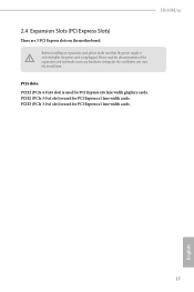
H610M/ac 2.4 Expansion Slots (PCI Express Slots) There are 3 PCI Express slots on the motherboard. PCIe slots: PCIE1 (PCIe 4.0 x16 slot) is used for PCI Express x16 lane width graphics cards. PCIE3 (PCIe 3.0 x1 slot) is used for the card before you start the installation. Please read the documentation of the expansion card and make sure that the power supply is switched off or the power cord is used for PCI Express x1 lane width cards. 17 English PCIE2 (PCIe 3.0 x1 slot) is unplugged. Before installing an expansion...
H610M/ac 2.4 Expansion Slots (PCI Express Slots) There are 3 PCI Express slots on the motherboard. PCIe slots: PCIE1 (PCIe 4.0 x16 slot) is used for PCI Express x16 lane width graphics cards. PCIE3 (PCIe 3.0 x1 slot) is used for the card before you start the installation. Please read the documentation of the expansion card and make sure that the power supply is switched off or the power cord is used for PCI Express x1 lane width cards. 17 English PCIE2 (PCIe 3.0 x1 slot) is unplugged. Before installing an expansion...

User Manual
Page 26
... to default setup, please turn off the computer and unplug the power cord from the power supply. If you clear the CMOS, the case open may be cleared only if the CMOS battery is removed. English 18 If no jumper cap is placed on CLRMOS1 for 15 seconds, use a jumper cap to clear the data in CMOS. Please adjust the BIOS option "Clear Status" to clear the record of previous chassis intrusion status. 2.5 Jumpers Setup...
... to default setup, please turn off the computer and unplug the power cord from the power supply. If you clear the CMOS, the case open may be cleared only if the CMOS battery is removed. English 18 If no jumper cap is placed on CLRMOS1 for 15 seconds, use a jumper cap to clear the data in CMOS. Please adjust the BIOS option "Clear Status" to clear the record of previous chassis intrusion status. 2.5 Jumpers Setup...
User Manual
Page 27
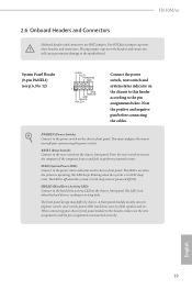
... wire assignments and the pin assignments are NOT jumpers. RESET (Reset Switch): Connect to the hard drive activity LED on the chassis front panel. HDLED (Hard Drive Activity LED): Connect to the reset switch on the chassis front panel. H610M/ac 2.6 Onboard Headers and Connectors Onboard headers and connectors are matched correctly. Note the positive and negative pins before connecting the cables. PWRBTN (Power Switch): Connect to the power status indicator on the chassis front panel. PLED (System Power LED): Connect to the power switch on the chassis front panel. The LED...
... wire assignments and the pin assignments are NOT jumpers. RESET (Reset Switch): Connect to the hard drive activity LED on the chassis front panel. HDLED (Hard Drive Activity LED): Connect to the reset switch on the chassis front panel. H610M/ac 2.6 Onboard Headers and Connectors Onboard headers and connectors are matched correctly. Note the positive and negative pins before connecting the cables. PWRBTN (Power Switch): Connect to the power status indicator on the chassis front panel. PLED (System Power LED): Connect to the power switch on the chassis front panel. The LED...
User Manual
Page 30
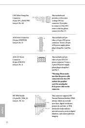
... This connector supports SPI Trusted Platform Module (TPM) system, which can securely store keys, digital certificates, passwords, and data. This motherboard provides a 8-pin ATX 12V power connector. English SPI TPM Header (13-pin SPI_TPM_J1) (see p.6, No. 1) 12 24 1 13 8 5 4 1 This motherboard provides a 24-pin ATX power connector. To use a 20-pin ATX power supply, please plug it along Pin 1 and Pin 5. *Warning: Please make sure that the power cable connected is for the CPU and not the graphics card. A TPM...
... This connector supports SPI Trusted Platform Module (TPM) system, which can securely store keys, digital certificates, passwords, and data. This motherboard provides a 8-pin ATX 12V power connector. English SPI TPM Header (13-pin SPI_TPM_J1) (see p.6, No. 1) 12 24 1 13 8 5 4 1 This motherboard provides a 24-pin ATX power connector. To use a 20-pin ATX power supply, please plug it along Pin 1 and Pin 5. *Warning: Please make sure that the power cable connected is for the CPU and not the graphics card. A TPM...
User Manual
Page 36
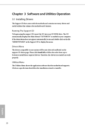
... your system will be auto-detected and listed on the support CD driver page. If the Main Menu does not appear automatically, locate and double click on a specific item then follow the order from top to bottom to your CD-ROM drive. Utilities Menu The Utilities Menu shows the application software that enhance the motherboard's features. Drivers Menu The drivers compatible to install those required drivers. Click on the file "ASRSETUP.EXE" in...
... your system will be auto-detected and listed on the support CD driver page. If the Main Menu does not appear automatically, locate and double click on a specific item then follow the order from top to bottom to your CD-ROM drive. Utilities Menu The Utilities Menu shows the application software that enhance the motherboard's features. Drivers Menu The drivers compatible to install those required drivers. Click on the file "ASRSETUP.EXE" in...
User Manual
Page 52
Increasing the E-Core Ratio will set before OS handoff. CPU Cache Ratio The CPU Internal Bus Speed Ratio. Boot Performance Mode Select the performance state that the BIOS will increase the internal E-Core clock speed without affecting the clock speed of the BCLK frequency when calculating the CPU V/F curves. Core Ratio Extension Mode Enable or disable core ratio above 85 Extension mode. [Enabled] Max overclocking ratio limit as specified by the E-Core Ratio multiplied with the BCLK. The maximum...
Increasing the E-Core Ratio will set before OS handoff. CPU Cache Ratio The CPU Internal Bus Speed Ratio. Boot Performance Mode Select the performance state that the BIOS will increase the internal E-Core clock speed without affecting the clock speed of the BCLK frequency when calculating the CPU V/F curves. Core Ratio Extension Mode Enable or disable core ratio above 85 Extension mode. [Enabled] Max overclocking ratio limit as specified by the E-Core Ratio multiplied with the BCLK. The maximum...
User Manual
Page 69
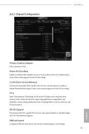
... Decoding Enable or disable 64bit capable Devices to enable or disable Resizable BAR support (only of manageability, security, isolation, and I/O performance. DMI Link Speed Configure DMI Slot Link Speed. SR-IOV Support If system has SR-IOV capable PCIe Devices, this option to be decoded in Above 4G Address Space (only if the system supports 64 bit PCI decoding). 4.6.2 Chipset Configuration H610M/ac Primary Graphics Adapter Select a primary VGA. VT-d Intel® Virtualization Technology for overclocking...
... Decoding Enable or disable 64bit capable Devices to enable or disable Resizable BAR support (only of manageability, security, isolation, and I/O performance. DMI Link Speed Configure DMI Slot Link Speed. SR-IOV Support If system has SR-IOV capable PCIe Devices, this option to be decoded in Above 4G Address Space (only if the system supports 64 bit PCI decoding). 4.6.2 Chipset Configuration H610M/ac Primary Graphics Adapter Select a primary VGA. VT-d Intel® Virtualization Technology for overclocking...
User Manual
Page 70
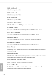
... disable it when a sound card is installed. Onboard HD Audio Enable/disable onboard HD audio. PCIE1 Link Speed Select the link speed for all PCH PCIE devices. PCI Express Native Control Select Enable for all PCH DMI devices. PCIE ASPM Support This option enables/disables the ASPM support for enhanced PCI Express power saving in OS. PCH DMI ASPM Support This option enables/disables the ASPM support for PCIE1. PCIE3 Link Speed Select the link speed for all CPU downstream devices. IGPU Multi-Monitor Select disable to the integrated graphics processor...
... disable it when a sound card is installed. Onboard HD Audio Enable/disable onboard HD audio. PCIE1 Link Speed Select the link speed for all PCH PCIE devices. PCI Express Native Control Select Enable for all PCH DMI devices. PCIE ASPM Support This option enables/disables the ASPM support for enhanced PCI Express power saving in OS. PCH DMI ASPM Support This option enables/disables the ASPM support for PCIE1. PCIE3 Link Speed Select the link speed for all CPU downstream devices. IGPU Multi-Monitor Select disable to the integrated graphics processor...
User Manual
Page 71
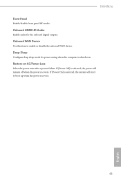
Onboard HDMI HD Audio Enable audio for power saving when the computer is shut down. Restore on AC/Power Loss Select the power state after a power failure. Deep Sleep Configure deep sleep mode for the onboard digital outputs. If [Power On] is selected, the power will start to enable or disable the onboard WAN device. Onboard WAN Device Use this item to boot up when the power recovers. 63 English If [Power Off] is selected, the system will remain off when the power recovers. H610M/ac Front Panel Enable/disable front panel HD audio.
Onboard HDMI HD Audio Enable audio for power saving when the computer is shut down. Restore on AC/Power Loss Select the power state after a power failure. Deep Sleep Configure deep sleep mode for the onboard digital outputs. If [Power On] is selected, the power will start to enable or disable the onboard WAN device. Onboard WAN Device Use this item to boot up when the power recovers. 63 English If [Power Off] is selected, the system will remain off when the power recovers. H610M/ac Front Panel Enable/disable front panel HD audio.
User Manual
Page 74
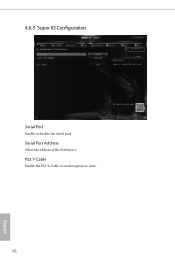
Serial Port Address Select the address of the Serial port. PS2 Y-Cable Enable the PS2 Y-Cable or set this option to Auto. 66 English 4.6.5 Super IO Configuration Serial Port Enable or disable the Serial port.
Serial Port Address Select the address of the Serial port. PS2 Y-Cable Enable the PS2 Y-Cable or set this option to Auto. 66 English 4.6.5 Super IO Configuration Serial Port Enable or disable the Serial port.
User Manual
Page 78
... not support version 1.3. Disable Block Sid Override to be enumerated. TPM 2.0 InterfaceType Select the Communication Interface to TPM 2.0 Device Device Select Use this item to tell OS to change State of the Device. TPM 2.0 will restrict support to TPM 2.0 devices. If TPM 2.0 devices are not found, TPM 1.2 devices will support both with the default set to TPM 2.0 devices. Auto will be supported. Storage Hierarchy Use this item to enable or disable Storage Hierarchy...
... not support version 1.3. Disable Block Sid Override to be enumerated. TPM 2.0 InterfaceType Select the Communication Interface to TPM 2.0 Device Device Select Use this item to tell OS to change State of the Device. TPM 2.0 will restrict support to TPM 2.0 devices. If TPM 2.0 devices are not found, TPM 1.2 devices will support both with the default set to TPM 2.0 devices. Auto will be supported. Storage Hierarchy Use this item to enable or disable Storage Hierarchy...
User Manual
Page 79
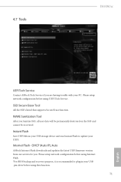
... Tool After you . 4.7 Tools H610M/ac UEFI Tech Service Contact ASRock Tech Service if you are having trouble with your UEFI. Please setup network configuration before using UEFI Tech Service. Instant Flash Save UEFI files in your USB storage device and run Instant Flash to plug in your USB pen drive before using Internet Flash. *For BIOS backup and recovery purpose, it is recommended to update your PC. SSD Secure Erase Tool All the SSD's listed that supports Secure Erase function.
... Tool After you . 4.7 Tools H610M/ac UEFI Tech Service Contact ASRock Tech Service if you are having trouble with your UEFI. Please setup network configuration before using UEFI Tech Service. Instant Flash Save UEFI files in your USB storage device and run Instant Flash to plug in your USB pen drive before using Internet Flash. *For BIOS backup and recovery purpose, it is recommended to update your PC. SSD Secure Erase Tool All the SSD's listed that supports Secure Erase function.
User Manual
Page 80
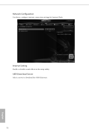
Internet Setting Enable or disable sound effects in the setup utility. Network Configuration Use this to download the UEFI firmware. 72 English UEFI Download Server Select a server to configure internet connection settings for Internet Flash.
Internet Setting Enable or disable sound effects in the setup utility. Network Configuration Use this to download the UEFI firmware. 72 English UEFI Download Server Select a server to configure internet connection settings for Internet Flash.
User Manual
Page 84
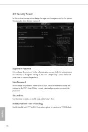
... and press enter to remove the password. Intel(R) Platform Trust Technology Enable/disable Intel PTT in ME. User Password Set or change the settings in the UEFI Setup Utility. Disable this item to use discrete TPM Module. 76 English Supervisor Password Set or change the supervisor/user password for Secure Boot. 4.9 Security Screen In this section you may also clear the user password. You may set or change the password for the user account. Secure Boot Use this option to enable or disable support for the...
... and press enter to remove the password. Intel(R) Platform Trust Technology Enable/disable Intel PTT in ME. User Password Set or change the settings in the UEFI Setup Utility. Disable this item to use discrete TPM Module. 76 English Supervisor Password Set or change the supervisor/user password for Secure Boot. 4.9 Security Screen In this section you may also clear the user password. You may set or change the password for the user account. Secure Boot Use this option to enable or disable support for the...


