
Intel Rapid Storage Guide
Page 12
... system onto a RAID volume, the RAID option must be enabled in the system BIOS. 1. Enable RAID in System BIOS Use the instructions included with your motherboard to enable RAID in the system BIOS, a RAID volume must be created, and the F6 installation method must be used to select the drive.
... system onto a RAID volume, the RAID option must be enabled in the system BIOS. 1. Enable RAID in System BIOS Use the instructions included with your motherboard to enable RAID in the system BIOS, a RAID volume must be created, and the F6 installation method must be used to select the drive.

RAID Installation Guide
Page 2
You may install SATA hard disks on this guide carefully according to create RAID on SATA ports. 2 This section will guide you how to the Intel southbridge chipset that your motherboard adopts. Please read the RAID configurations in this motherboard for internal storage devices. Guide to SATA Hard Disks Installation 1.1 Serial ATA (SATA) Hard Disks Installation Intel chipset supports Serial ATA (SATA) hard disks with RAID functions, including RAID 0, RAID 1, RAID 5, RAID 10 and Intel Rapid Storage. 1.
You may install SATA hard disks on this guide carefully according to create RAID on SATA ports. 2 This section will guide you how to the Intel southbridge chipset that your motherboard adopts. Please read the RAID configurations in this motherboard for internal storage devices. Guide to SATA Hard Disks Installation 1.1 Serial ATA (SATA) Hard Disks Installation Intel chipset supports Serial ATA (SATA) hard disks with RAID functions, including RAID 0, RAID 1, RAID 5, RAID 10 and Intel Rapid Storage. 1.

RAID Installation Guide
Page 3
... not provide any HDDs of a single disk alone while the two hard disks perform the same work as it contains a complete copy of RAID This motherboard adopts Intel southbridge chipset that optimizes two identical hard disk drives to RAID Configurations 2.1 Introduction of the data in parallel, interleaved stacks. Guide to read...
... not provide any HDDs of a single disk alone while the two hard disks perform the same work as it contains a complete copy of RAID This motherboard adopts Intel southbridge chipset that optimizes two identical hard disk drives to RAID Configurations 2.1 Introduction of the data in parallel, interleaved stacks. Guide to read...

RAID Installation Guide
Page 23
STEP 1: Copy Intel® RAID drivers into a USB flash disk You can download the drivers from ASRock's website and unzip the files into a USB flash disk or copy the files from ASRock's motherboard support CD. (Please copy the files under the following directory: 32 bit: ..\i386\Win7_Intel.. 64-bit: ..\AMD64\Win7-64_Intel.. STEP 2: Install...
STEP 1: Copy Intel® RAID drivers into a USB flash disk You can download the drivers from ASRock's website and unzip the files into a USB flash disk or copy the files from ASRock's motherboard support CD. (Please copy the files under the following directory: 32 bit: ..\i386\Win7_Intel.. 64-bit: ..\AMD64\Win7-64_Intel.. STEP 2: Install...

RAID Installation Guide
Page 25
... fix this problem, you install Windows® 10 64-bit on a large hard disk (ex. Reboot your system. (It may take more time to install motherboard drivers and utilities. 25 E. Please start to boot into Windows® or install driver/utilities. If you will install this link: http://support.microsoft.com...
... fix this problem, you install Windows® 10 64-bit on a large hard disk (ex. Reboot your system. (It may take more time to install motherboard drivers and utilities. 25 E. Please start to boot into Windows® or install driver/utilities. If you will install this link: http://support.microsoft.com...

User Manual
Page 2
... in California, USA, please follow the related regulations in Perchlorate Best Management Practices (BMP) regulations passed by ASRock. ASRock assumes no event shall ASRock, its directors, officers, employees, or agents be reproduced, transcribed, transmitted, or translated in any language, ...-special handling may not be constructed as a commitment by the California Legislature. Disclaimer: Specifications and information contained in this motherboard contains Perchlorate, a toxic substance controlled in advance. With respect to the owners' benefit, without notice, and should not...
... in California, USA, please follow the related regulations in Perchlorate Best Management Practices (BMP) regulations passed by ASRock. ASRock assumes no event shall ASRock, its directors, officers, employees, or agents be reproduced, transcribed, transmitted, or translated in any language, ...-special handling may not be constructed as a commitment by the California Legislature. Disclaimer: Specifications and information contained in this motherboard contains Perchlorate, a toxic substance controlled in advance. With respect to the owners' benefit, without notice, and should not...

User Manual
Page 4
Contents Chapter 1 Introduction 1 1.1 Package Contents 1 1.2 Specifications 2 1.3 Motherboard Layout 7 1.4 I/O Panel 9 Chapter 2 Installation 11 2.1 Installing the CPU 12 2.2 Installing the CPU Fan and Heatsink 15 2.3 Installing Memory Modules (DIMM) 16 2.4 Expansion Slots (PCI Express ... WiFi/BT) Installation Guide 27 2.9 M.2_SSD (NGFF) Module Installation Guide (M2_1 and M2_2) 29 Chapter 3 Software and Utilities Operation 33 3.1 Installing Drivers 33 3.2 A-Tuning 34 3.3 ASRock Live Update & APP Shop 37
Contents Chapter 1 Introduction 1 1.1 Package Contents 1 1.2 Specifications 2 1.3 Motherboard Layout 7 1.4 I/O Panel 9 Chapter 2 Installation 11 2.1 Installing the CPU 12 2.2 Installing the CPU Fan and Heatsink 15 2.3 Installing Memory Modules (DIMM) 16 2.4 Expansion Slots (PCI Express ... WiFi/BT) Installation Guide 27 2.9 M.2_SSD (NGFF) Module Installation Guide (M2_1 and M2_2) 29 Chapter 3 Software and Utilities Operation 33 3.1 Installing Drivers 33 3.2 A-Tuning 34 3.3 ASRock Live Update & APP Shop 37
User Manual
Page 6
... documentation will be subject to change without further notice. ASRock website http://www.asrock.com. 1.1 Package Contents • ASRock H370M Pro4 Motherboard (Micro ATX Form Factor) • ASRock H370M Pro4 Quick Installation Guide • ASRock H370M Pro4 Support CD • 2 x Serial ATA (SATA) Data Cables (Optional) • 3 x Screws for purchasing ASRock H370M Pro4 motherboard, a reliable motherboard produced under ASRock's consistently stringent quality control. You may find the latest...
... documentation will be subject to change without further notice. ASRock website http://www.asrock.com. 1.1 Package Contents • ASRock H370M Pro4 Motherboard (Micro ATX Form Factor) • ASRock H370M Pro4 Quick Installation Guide • ASRock H370M Pro4 Support CD • 2 x Serial ATA (SATA) Data Cables (Optional) • 3 x Screws for purchasing ASRock H370M Pro4 motherboard, a reliable motherboard produced under ASRock's consistently stringent quality control. You may find the latest...

User Manual
Page 12
1.3 Motherboard Layout ATX12V1 CPU_FAN1 H370M Pro4 CPU_FAN2/WP PS2 Mouse PS2 Keyboard VGA1 DVI1 ATXPWR1 DDR4_A1 (64 bit, 288-pin module) DDR4_A2 (64 bit, 288-pin module) DDR4_B1 (64 bit, 288-.../WP Top: LINE IN Center: FRONT Bottom: MIC IN CMOS Battery PCIE1 USB 3.1 Gen2 PCIE2 PCIE3 HD_AUDIO1 1 PCIE4 RoHS COM1 1 M2_3 M2_1 CHA_FAN2/WP SATA3_2 H370M Pro4 Intel H370 Ultra M.2 PCIe Gen3 x4 SATA3_4 M2_2 TPMS1 1 USB5 1 USB3_4 1 CLRMOS1 SPK_CI1 1 1 PLED PWRBTN 1 HDLED RESET PANEL1 USB3_7_8 1 USB3_5_6 1 SATA3_3 SATA3_5 English...
1.3 Motherboard Layout ATX12V1 CPU_FAN1 H370M Pro4 CPU_FAN2/WP PS2 Mouse PS2 Keyboard VGA1 DVI1 ATXPWR1 DDR4_A1 (64 bit, 288-pin module) DDR4_A2 (64 bit, 288-pin module) DDR4_B1 (64 bit, 288-.../WP Top: LINE IN Center: FRONT Bottom: MIC IN CMOS Battery PCIE1 USB 3.1 Gen2 PCIE2 PCIE3 HD_AUDIO1 1 PCIE4 RoHS COM1 1 M2_3 M2_1 CHA_FAN2/WP SATA3_2 H370M Pro4 Intel H370 Ultra M.2 PCIe Gen3 x4 SATA3_4 M2_2 TPMS1 1 USB5 1 USB3_4 1 CLRMOS1 SPK_CI1 1 1 PLED PWRBTN 1 HDLED RESET PANEL1 USB3_7_8 1 USB3_5_6 1 SATA3_3 SATA3_5 English...

User Manual
Page 16
... order to avoid damage from static electricity to the motherboard's components, NEVER place your chassis to ensure that comes with the components. • When placing screws to secure the motherboard to unplug the power cord before you uninstall any components, place them on a carpet. H370M Pro4 Chapter 2 Installation This is a Micro ATX form factor...
... order to avoid damage from static electricity to the motherboard's components, NEVER place your chassis to ensure that comes with the components. • When placing screws to secure the motherboard to unplug the power cord before you uninstall any components, place them on a carpet. H370M Pro4 Chapter 2 Installation This is a Micro ATX form factor...

User Manual
Page 19
Please save and replace the cover if the processor is removed. The cover must be placed if you wish to return the motherboard for after service. 14 English
Please save and replace the cover if the processor is removed. The cover must be placed if you wish to return the motherboard for after service. 14 English

User Manual
Page 21
... four 288-pin DDR4 (Double Data Rate 4) DIMM slots, and supports Dual Channel Memory Technology. 1. It is unable to the motherboard and the DIMM if you always need to install a DDR, DDR2 or DDR3 memory module into the slot at incorrect orientation. For dual channel configuration, ...
... four 288-pin DDR4 (Double Data Rate 4) DIMM slots, and supports Dual Channel Memory Technology. 1. It is unable to the motherboard and the DIMM if you always need to install a DDR, DDR2 or DDR3 memory module into the slot at incorrect orientation. For dual channel configuration, ...

User Manual
Page 23
2.4 Expansion Slots (PCI Express Slots) There are 4 PCI Express slots on the motherboard. Before installing an expansion card, please make necessary hardware settings for the card before you start the installation. PCIE4 (PCIe 3.0 x16 slot) is used for... * If PCIE2 is used for PCI Express x16 lane width graphics cards. PCIe slots: PCIE1 (PCIe 3.0 x16 slot) is occupied, PCIE4 will downgrade to the motherboard's chassis fan connector (CHA_FAN1 or CHA_FAN2) when using multiple graphics cards. PCIE3 (PCIe 3.0 x1 slot) is unplugged. Please read the documentation of the expansion card...
2.4 Expansion Slots (PCI Express Slots) There are 4 PCI Express slots on the motherboard. Before installing an expansion card, please make necessary hardware settings for the card before you start the installation. PCIE4 (PCIe 3.0 x16 slot) is used for... * If PCIE2 is used for PCI Express x16 lane width graphics cards. PCIe slots: PCIE1 (PCIe 3.0 x16 slot) is occupied, PCIE4 will downgrade to the motherboard's chassis fan connector (CHA_FAN1 or CHA_FAN2) when using multiple graphics cards. PCIE3 (PCIe 3.0 x1 slot) is unplugged. Please read the documentation of the expansion card...

User Manual
Page 25
... to the power switch on the chassis front panel. HDLED (Hard Drive Activity LED): Connect to turn off your chassis front panel module to the motherboard. 2.6 Onboard Headers and Connectors Onboard headers and connectors are matched correctly. You may differ by chassis. PLED (System Power LED): Connect to perform a normal restart...
... to the power switch on the chassis front panel. HDLED (Hard Drive Activity LED): Connect to turn off your chassis front panel module to the motherboard. 2.6 Onboard Headers and Connectors Onboard headers and connectors are matched correctly. You may differ by chassis. PLED (System Power LED): Connect to perform a normal restart...

User Manual
Page 26
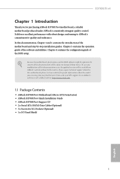
... GND IntA_PA_SSTXIntA_PA_SSTX+ GND IntA_PA_DIntA_PA_D+ Vbus IntA_PB_SSRXIntA_PB_SSRX+ GND IntA_PB_SSTXIntA_PB_SSTX+ GND IntA_PB_DIntA_PB_D+ Dummy 1 There are two headers on this motherboard. SATA3_5 SATA3_3 SATA3_4 SATA3_2 USB_PWR PP+ GND DUMMY 1 GND P+ PUSB_PWR 1 GND P- If M2_2 is for internal...) GND PRESENCE# MIC_RET OUT_RET 1 OUT2_L J_SENSE OUT2_R MIC2_R MIC2_L This header is occupied by a SATA-type M.2 device, SATA3_1 will be disabled. H370M Pro4 SATA3_1 SATA3_0 Serial ATA3 Connectors (SATA3_0: see p.7, No. 8) (SATA3_1: see p.7, No. 9) (SATA3_2: see p.7, No. 12) (SATA3_3...
... GND IntA_PA_SSTXIntA_PA_SSTX+ GND IntA_PA_DIntA_PA_D+ Vbus IntA_PB_SSRXIntA_PB_SSRX+ GND IntA_PB_SSTXIntA_PB_SSTX+ GND IntA_PB_DIntA_PB_D+ Dummy 1 There are two headers on this motherboard. SATA3_5 SATA3_3 SATA3_4 SATA3_2 USB_PWR PP+ GND DUMMY 1 GND P+ PUSB_PWR 1 GND P- If M2_2 is for internal...) GND PRESENCE# MIC_RET OUT_RET 1 OUT2_L J_SENSE OUT2_R MIC2_R MIC2_L This header is occupied by a SATA-type M.2 device, SATA3_1 will be disabled. H370M Pro4 SATA3_1 SATA3_0 Serial ATA3 Connectors (SATA3_0: see p.7, No. 8) (SATA3_1: see p.7, No. 9) (SATA3_2: see p.7, No. 12) (SATA3_3...

User Manual
Page 27
...CPU Fan Connector (4-pin CPU_FAN1) (see p.7, No. 10) 4 3 2 1 FAN_SPEED_CONTROL CHA_FAN_SPEED FAN_VOLTAGE GND GND FAN_VOLTAGE_CONTROL FAN_SPEED FAN_SPEED_CONTROL This motherboard provides two 4-Pin water cooling chassis fan connectors. If you plan to connect a 3-Pin chassis water cooler fan, please connect it...install it to the front panel audio header by the steps below: A. English 22 CPU/Water Pump Fan FAN_SPEED This motherboard FAN_VOLTAGE_CONTROL Connector GND FAN_SPEED_CONTROL provides a 4-Pin water (4-pin CPU_FAN2/WP) cooling CPU fan (see p.7, No. 5) connector...
...CPU Fan Connector (4-pin CPU_FAN1) (see p.7, No. 10) 4 3 2 1 FAN_SPEED_CONTROL CHA_FAN_SPEED FAN_VOLTAGE GND GND FAN_VOLTAGE_CONTROL FAN_SPEED FAN_SPEED_CONTROL This motherboard provides two 4-Pin water cooling chassis fan connectors. If you plan to connect a 3-Pin chassis water cooler fan, please connect it...install it to the front panel audio header by the steps below: A. English 22 CPU/Water Pump Fan FAN_SPEED This motherboard FAN_VOLTAGE_CONTROL Connector GND FAN_SPEED_CONTROL provides a 4-Pin water (4-pin CPU_FAN2/WP) cooling CPU fan (see p.7, No. 5) connector...
User Manual
Page 28
... it along Pin 1 and Pin 5. A TPM system also helps enhance network security, protects digital identities, and ensures platform integrity. English 23 This motherboard provides a 8-pin ATX 12V power connector. H370M Pro4 ATX Power Connector (24-pin ATXPWR1) (see p.7, No. 6) ATX 12V Power Connector (8-pin ATX12V1) (see p.7, No. 1) Serial Port Header (9-pin COM1) (see...
... it along Pin 1 and Pin 5. A TPM system also helps enhance network security, protects digital identities, and ensures platform integrity. English 23 This motherboard provides a 8-pin ATX 12V power connector. H370M Pro4 ATX Power Connector (24-pin ATXPWR1) (see p.7, No. 6) ATX 12V Power Connector (8-pin ATX12V1) (see p.7, No. 1) Serial Port Header (9-pin COM1) (see...

User Manual
Page 29
... PCIE4 slot. Make sure that the cards are AMD certified. 2. 2.7 CrossFireXTM and Quad CrossFireXTM Operation Guide This motherboard supports CrossFireXTM and Quad CrossFireXTM that allows you pair a 12-pipe CrossFireXTM Edition card with this motherboard. Make sure that are properly seated on the top of the graphics cards. (The CrossFire Bridge is...
... PCIE4 slot. Make sure that the cards are AMD certified. 2. 2.7 CrossFireXTM and Quad CrossFireXTM Operation Guide This motherboard supports CrossFireXTM and Quad CrossFireXTM that allows you pair a 12-pipe CrossFireXTM Edition card with this motherboard. Make sure that are properly seated on the top of the graphics cards. (The CrossFire Bridge is...

User Manual
Page 35
Please do not overtighten the screw as this might damage the module. Step 4 Peel off the yellow protective film on the motherboard. English E D NUT2 NUT1 30 Step 6 Tighten the screw with a screwdriver to use the default nut. Hand tighten the standoff into the desired nut location on ...
Please do not overtighten the screw as this might damage the module. Step 4 Peel off the yellow protective film on the motherboard. English E D NUT2 NUT1 30 Step 6 Tighten the screw with a screwdriver to use the default nut. Hand tighten the standoff into the desired nut location on ...
User Manual
Page 38
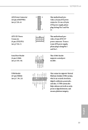
...click on the file "ASRSETUP.EXE" in your CD-ROM drive. H370M Pro4 Chapter 3 Software and Utilities Operation 3.1 Installing Drivers The Support CD that comes with the motherboard contains necessary drivers and useful utilities that the motherboard supports. Running The Support CD To begin using the support CD, ...insert the CD into your computer. Utilities Menu The Utilities Menu shows the application software that enhance the motherboard's features. The CD automatically displays the Main Menu if "AUTORUN" is enabled in the Support CD to your system will be ...
...click on the file "ASRSETUP.EXE" in your CD-ROM drive. H370M Pro4 Chapter 3 Software and Utilities Operation 3.1 Installing Drivers The Support CD that comes with the motherboard contains necessary drivers and useful utilities that the motherboard supports. Running The Support CD To begin using the support CD, ...insert the CD into your computer. Utilities Menu The Utilities Menu shows the application software that enhance the motherboard's features. The CD automatically displays the Main Menu if "AUTORUN" is enabled in the Support CD to your system will be ...

