
User Manual
Page 2
... not limited to the following two conditions: (1) this device may not cause harmful interference, and (2) this documentation, ASRock does not provide warranty of merchantability or fitness for any defect or error in this motherboard contains Perchlorate, a toxic substance controlled in advance. With respect to the contents of this device must accept any...
... not limited to the following two conditions: (1) this device may not cause harmful interference, and (2) this documentation, ASRock does not provide warranty of merchantability or fitness for any defect or error in this motherboard contains Perchlorate, a toxic substance controlled in advance. With respect to the contents of this device must accept any...
User Manual
Page 4
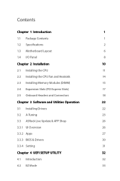
... 1 1.1 Package Contents 1 1.2 Specifications 2 1.3 Motherboard Layout 6 1.4 I/O Panel 8 Chapter 2 Installation 10 2.1 Installing the CPU 11 2.2 Installing the CPU Fan and Heatsink 14 2.3 Installing Memory Modules (DIMM) 15 2.4 Expansion Slots (PCI Express Slots) 17 2.5 Onboard Headers and Connectors 18 Chapter 3 Software and Utilities Operation 22 3.1 Installing Drivers 22 3.2 A-Tuning 23 3.3 ASRock Live Update & APP Shop...
... 1 1.1 Package Contents 1 1.2 Specifications 2 1.3 Motherboard Layout 6 1.4 I/O Panel 8 Chapter 2 Installation 10 2.1 Installing the CPU 11 2.2 Installing the CPU Fan and Heatsink 14 2.3 Installing Memory Modules (DIMM) 15 2.4 Expansion Slots (PCI Express Slots) 17 2.5 Onboard Headers and Connectors 18 Chapter 3 Software and Utilities Operation 22 3.1 Installing Drivers 22 3.2 A-Tuning 23 3.3 ASRock Live Update & APP Shop...
User Manual
Page 6
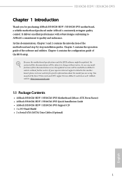
... visit our website for specific information about the model you for purchasing ASRock H310CM-HDV / H310CM-DVS motherboard, a reliable motherboard produced under ASRock's consistently stringent quality control. ASRock website http://www.asrock.com. 1.1 Package Contents • ASRock H310CM-HDV / H310CM-DVS Motherboard (Micro ATX Form Factor) • ASRock H310CM-HDV / H310CM-DVS Quick Installation Guide • ASRock H310CM-HDV / H310CM-DVS Support CD • 1 x I/O Panel Shield • 2 x Serial ATA (SATA) Data Cables...
... visit our website for specific information about the model you for purchasing ASRock H310CM-HDV / H310CM-DVS motherboard, a reliable motherboard produced under ASRock's consistently stringent quality control. ASRock website http://www.asrock.com. 1.1 Package Contents • ASRock H310CM-HDV / H310CM-DVS Motherboard (Micro ATX Form Factor) • ASRock H310CM-HDV / H310CM-DVS Quick Installation Guide • ASRock H310CM-HDV / H310CM-DVS Support CD • 1 x I/O Panel Shield • 2 x Serial ATA (SATA) Data Cables...
User Manual
Page 11
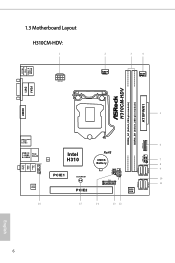
USB 2.0 T: USB1 B: USB2 PS2 Keyboard /Mouse HDMI1 1.3 Motherboard Layout H310CM-HDV: 1 ATX12V1 2 CPU_FAN1 3 4 CHA_FAN1/WP ATXPWR1 H310CM-HDV DDR4_A1 (64 bit, 288-pin module) DDR4_B1 (64 bit, 288-pin module) VGA1 DVI1 5 USB 3.1 Gen1 T: USB1 B: USB2 6 USB3_3_4 Top: LINE IN Center: FRONT Bottom: MIC IN USB 2.0 Top: T: USB3 RJ-45 B: USB4 LAN HD_AUDIO1 Intel H310 RoHS CMOS Battery USB_5_6 1 7 1 8 9 SATA3_2 SATA3_3 SPK_CI1 1 PLED PWRBTN PANEL1 1 HDLED RESET 1 PCIE1 CLRCMOS1 10 TPMS1 1 11 SATA3_0 SATA3_1 AUDIO CODEC PCIE2 BIOS ROM 16 15 14 13 12 English 6
USB 2.0 T: USB1 B: USB2 PS2 Keyboard /Mouse HDMI1 1.3 Motherboard Layout H310CM-HDV: 1 ATX12V1 2 CPU_FAN1 3 4 CHA_FAN1/WP ATXPWR1 H310CM-HDV DDR4_A1 (64 bit, 288-pin module) DDR4_B1 (64 bit, 288-pin module) VGA1 DVI1 5 USB 3.1 Gen1 T: USB1 B: USB2 6 USB3_3_4 Top: LINE IN Center: FRONT Bottom: MIC IN USB 2.0 Top: T: USB3 RJ-45 B: USB4 LAN HD_AUDIO1 Intel H310 RoHS CMOS Battery USB_5_6 1 7 1 8 9 SATA3_2 SATA3_3 SPK_CI1 1 PLED PWRBTN PANEL1 1 HDLED RESET 1 PCIE1 CLRCMOS1 10 TPMS1 1 11 SATA3_0 SATA3_1 AUDIO CODEC PCIE2 BIOS ROM 16 15 14 13 12 English 6

User Manual
Page 17
...; In order to avoid damage from static electricity to ensure that comes with the components. • When placing screws to secure the motherboard to unplug the power cord before you handle the components. • Hold components by the edges and do not touch the ICs. ...• Whenever you install the motherboard, study the configuration of your chassis to the motherboard's components, NEVER place your motherboard directly on a carpet. Pre-installation Precautions Take note of the following precautions before you install...
...; In order to avoid damage from static electricity to ensure that comes with the components. • When placing screws to secure the motherboard to unplug the power cord before you handle the components. • Hold components by the edges and do not touch the ICs. ...• Whenever you install the motherboard, study the configuration of your chassis to the motherboard's components, NEVER place your motherboard directly on a carpet. Pre-installation Precautions Take note of the following precautions before you install...
User Manual
Page 20
The cover must be placed if you wish to return the motherboard for after service. 15 English H310CM-HDV / H310CM-DVS Please save and replace the cover if the processor is removed.
The cover must be placed if you wish to return the motherboard for after service. 15 English H310CM-HDV / H310CM-DVS Please save and replace the cover if the processor is removed.
User Manual
Page 22
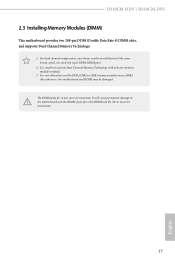
...install a DDR, DDR2 or DDR3 memory module into the slot at incorrect orientation. 17 English It will cause permanent damage to the motherboard and the DIMM if you always need to activate Dual Channel Memory Technology with only one correct orientation. The DIMM only fits in one... DIMM into a DDR4 slot; It is unable to install identical (the same brand, speed, size and chip-type) DDR4 DIMM pairs. 2. H310CM-HDV / H310CM-DVS 2.3 Installing Memory Modules (DIMM) This motherboard provides two 288-pin DDR4 (Double Data Rate 4) DIMM slots, and supports Dual Channel Memory Technology. 1.
...install a DDR, DDR2 or DDR3 memory module into the slot at incorrect orientation. 17 English It will cause permanent damage to the motherboard and the DIMM if you always need to activate Dual Channel Memory Technology with only one correct orientation. The DIMM only fits in one... DIMM into a DDR4 slot; It is unable to install identical (the same brand, speed, size and chip-type) DDR4 DIMM pairs. 2. H310CM-HDV / H310CM-DVS 2.3 Installing Memory Modules (DIMM) This motherboard provides two 288-pin DDR4 (Double Data Rate 4) DIMM slots, and supports Dual Channel Memory Technology. 1.
User Manual
Page 24
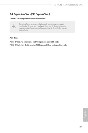
PCIe slots: PCIE1 (PCIe 2.0 x1 slot) is used for the card before you start the installation. PCIE2 (PCIe 3.0 x16 slot) is used for PCI Express x16 lane width graphics cards. 19 English Before installing an expansion card, please make necessary hardware settings for PCI Express x1 lane width cards. Please read the documentation of the expansion card and make sure that the power supply is switched off or the power cord is unplugged. H310CM-HDV / H310CM-DVS 2.4 Expansion Slots (PCI Express Slots) There are 2 PCI Express slots on the motherboard.
PCIe slots: PCIE1 (PCIe 2.0 x1 slot) is used for the card before you start the installation. PCIE2 (PCIe 3.0 x16 slot) is used for PCI Express x16 lane width graphics cards. 19 English Before installing an expansion card, please make necessary hardware settings for PCI Express x1 lane width cards. Please read the documentation of the expansion card and make sure that the power supply is switched off or the power cord is unplugged. H310CM-HDV / H310CM-DVS 2.4 Expansion Slots (PCI Express Slots) There are 2 PCI Express slots on the motherboard.
User Manual
Page 25
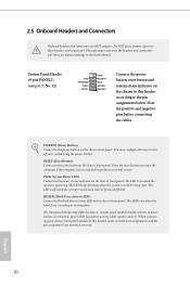
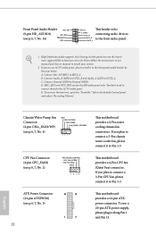
... cause permanent damage to the reset button on when the hard drive is operating. You may differ by chassis. RESET (Reset Button): Connect to the motherboard. A front panel module mainly consists of power button, reset button, power LED, hard drive activity LED, speaker and etc. English 20 System Panel Header (9-pin...
... cause permanent damage to the reset button on when the hard drive is operating. You may differ by chassis. RESET (Reset Button): Connect to the motherboard. A front panel module mainly consists of power button, reset button, power LED, hard drive activity LED, speaker and etc. English 20 System Panel Header (9-pin...
User Manual
Page 26
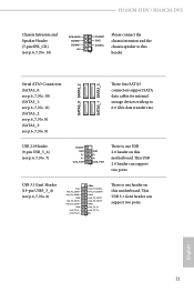
... USB 3.1 Gen1 header can support two ports. English 21 USB_PWR GND P+ PUSB_PWR 1 There is one USB 2.0 header on this motherboard. H310CM-HDV / H310CM-DVS Chassis Intrusion and Speaker Header (7-pin SPK_CI1) (see p.6, 7, No. 14) SPEAKER DUMMY DUMMY +5V DUMMY GND SIGNAL 1 Please connect the chassis intrusion and the chassis ...
... USB 3.1 Gen1 header can support two ports. English 21 USB_PWR GND P+ PUSB_PWR 1 There is one USB 2.0 header on this motherboard. H310CM-HDV / H310CM-DVS Chassis Intrusion and Speaker Header (7-pin SPK_CI1) (see p.6, 7, No. 14) SPEAKER DUMMY DUMMY +5V DUMMY GND SIGNAL 1 Please connect the chassis intrusion and the chassis ...
User Manual
Page 27
... (GND). B. Chassis/Water Pump Fan Connector (4-pin CHA_FAN1/WP) (see p.6, 7, No. 2) FAN_SPEED_CONTROL CPU_FAN_SPEED FAN_VOLTAGE GND 1 2 34 This motherboard provides a 4-Pin CPU fan (Quiet Fan) connector. To use an AC'97 audio panel, please install it to Pin 1-3. Connect Ground (GND...) to the front audio panel. CPU Fan Connector (4-pin CPU_FAN1) (see p.6, 7, No. 4) GND FAN_VOLTAGE FAN_SPEED FAN_SPEED_CONTROL 1 2 34 This motherboard provides a 4-Pin water cooling chassis fan connectors. English D. To activate the front mic, go to the front panel audio header by the steps...
... (GND). B. Chassis/Water Pump Fan Connector (4-pin CHA_FAN1/WP) (see p.6, 7, No. 2) FAN_SPEED_CONTROL CPU_FAN_SPEED FAN_VOLTAGE GND 1 2 34 This motherboard provides a 4-Pin CPU fan (Quiet Fan) connector. To use an AC'97 audio panel, please install it to Pin 1-3. Connect Ground (GND...) to the front audio panel. CPU Fan Connector (4-pin CPU_FAN1) (see p.6, 7, No. 4) GND FAN_VOLTAGE FAN_SPEED FAN_SPEED_CONTROL 1 2 34 This motherboard provides a 4-Pin water cooling chassis fan connectors. English D. To activate the front mic, go to the front panel audio header by the steps...
User Manual
Page 28
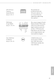
.... 13) Clear CMOS Pad (CLRMOS1) (see p.6, 7, No. 15) GND SERIRQ # S_PWRDWN # GN D LAD1 LAD2 SMB_DATA_MAIN SMB_CLK_MAIN GN D +3VS B LAD0 +3V LAD3 PCIRST # FRAM E PCICLK H310CM-HDV / H310CM-DVS 8 5 This motherboard provides an 8-pin ATX 4 1 12V power connector. CLRMOS1 allows you to clear the data in CMOS. To clear CMOS, take out the CMOS battery...
.... 13) Clear CMOS Pad (CLRMOS1) (see p.6, 7, No. 15) GND SERIRQ # S_PWRDWN # GN D LAD1 LAD2 SMB_DATA_MAIN SMB_CLK_MAIN GN D +3VS B LAD0 +3V LAD3 PCIRST # FRAM E PCICLK H310CM-HDV / H310CM-DVS 8 5 This motherboard provides an 8-pin ATX 4 1 12V power connector. CLRMOS1 allows you to clear the data in CMOS. To clear CMOS, take out the CMOS battery...
User Manual
Page 29
... the order from top to bottom to install it. 24 English Chapter 3 Software and Utilities Operation 3.1 Installing Drivers The Support CD that comes with the motherboard contains necessary drivers and useful utilities that the motherboard supports. Utilities Menu The Utilities Menu shows the application software that enhance the...
... the order from top to bottom to install it. 24 English Chapter 3 Software and Utilities Operation 3.1 Installing Drivers The Support CD that comes with the motherboard contains necessary drivers and useful utilities that the motherboard supports. Utilities Menu The Utilities Menu shows the application software that enhance the...

User Manual
Page 33
... the website of the selected news and know more. 28 English You can optimize your system and keep your motherboard up to date simply with a few clicks. 3.3 ASRock Live Update & APP Shop The ASRock Live Update & APP Shop is an online store for purchasing and downloading software applications for your desktop to access...
... the website of the selected news and know more. 28 English You can optimize your system and keep your motherboard up to date simply with a few clicks. 3.3 ASRock Live Update & APP Shop The ASRock Live Update & APP Shop is an online store for purchasing and downloading software applications for your desktop to access...
User Manual
Page 46
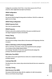
... motherboard will detect the memory module(s) inserted and assign the appropriate frequency automatically. DRAM Timing Configuration DRAM Frequency Clock Select Auto for optimized settings. Secondary Timing Write Recovery Time (tWR) The amount of delay that must elapse after the completion of the GT slice. A lower limit can be issued. H310CM-HDV / H310CM-DVS Configure...
... motherboard will detect the memory module(s) inserted and assign the appropriate frequency automatically. DRAM Timing Configuration DRAM Frequency Clock Select Auto for optimized settings. Secondary Timing Write Recovery Time (tWR) The amount of delay that must elapse after the completion of the GT slice. A lower limit can be issued. H310CM-HDV / H310CM-DVS Configure...
User Manual
Page 64
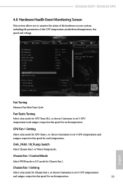
H310CM-HDV / H310CM-DVS 4.8 Hardware Health Event Monitoring Screen This section allows you to set 5 CPU temperatures and assign a respective fan speed for each temperature. Fan-Tastic Tuning Select a ... DC mode for Chassis Fan 1, or choose Customize to monitor the status of the hardware on your system, including the parameters of the CPU temperature, motherboard temperature, fan speed and voltage. CHA_FAN1 / W_Pump Switch Select Chassis Fan 1 or Water Pump mode. Fan Tuning Measure Fan Min Duty Cycle. CPU Fan 1 Setting...
H310CM-HDV / H310CM-DVS 4.8 Hardware Health Event Monitoring Screen This section allows you to set 5 CPU temperatures and assign a respective fan speed for each temperature. Fan-Tastic Tuning Select a ... DC mode for Chassis Fan 1, or choose Customize to monitor the status of the hardware on your system, including the parameters of the CPU temperature, motherboard temperature, fan speed and voltage. CHA_FAN1 / W_Pump Switch Select Chassis Fan 1 or Water Pump mode. Fan Tuning Measure Fan Min Duty Cycle. CPU Fan 1 Setting...
User Manual
Page 72
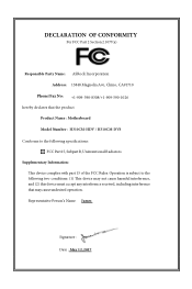
...James Signature : Date : May 12, 2017 DECLARATION OF CONFORMITY Per FCC Part 2 Section 2.1077(a) Responsible Party Name: ASRock Incorporation Address: 13848 Magnolia Ave, Chino, CA91710 Phone/Fax No: +1-909-590-8308/+1-909-590-1026 hereby declares that ...not cause harmful interference, and (2) this device must accept any interference received, including interference that the product Product Name : Motherboard Model Number : H310CM-HDV / H310CM-DVS Conforms to the following speci cations: FCC Part15, SubpartB,Unintentional Radiators Supplementary Information: is device complies with part 15 of ...
...James Signature : Date : May 12, 2017 DECLARATION OF CONFORMITY Per FCC Part 2 Section 2.1077(a) Responsible Party Name: ASRock Incorporation Address: 13848 Magnolia Ave, Chino, CA91710 Phone/Fax No: +1-909-590-8308/+1-909-590-1026 hereby declares that ...not cause harmful interference, and (2) this device must accept any interference received, including interference that the product Product Name : Motherboard Model Number : H310CM-HDV / H310CM-DVS Conforms to the following speci cations: FCC Part15, SubpartB,Unintentional Radiators Supplementary Information: is device complies with part 15 of ...
User Manual
Page 73
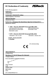
... Address) Person responsible for making this declaration: (Name, Surname) A.V.P (Position / Title) July 20, 2018 (Date) P/N: 15G062109000AK V1.0 EU Declaration of Conformity For the following equipment: Motherboard (Product Name) H310CM-HDV / H310CM-DVS / ASRock (Model Designation / Trade Name) ASRock Incorporation (Manufacturer Name) 2F., No.37, Sec. 2, Jhongyang S.
... Address) Person responsible for making this declaration: (Name, Surname) A.V.P (Position / Title) July 20, 2018 (Date) P/N: 15G062109000AK V1.0 EU Declaration of Conformity For the following equipment: Motherboard (Product Name) H310CM-HDV / H310CM-DVS / ASRock (Model Designation / Trade Name) ASRock Incorporation (Manufacturer Name) 2F., No.37, Sec. 2, Jhongyang S.


