
User Manual
Page 4
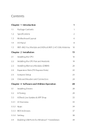
Contents Chapter 1 Introduction 1 1.1 Package Contents 1 1.2 Speciications 2 1.3 Motherboard Layout 6 1.4 I/O Panel 8 1.5 WiFi-802.11ac Module and ASRock WiFi 2.4/5 GHz Antenna 10 Chapter 2 Installation 15 2.1 Installing the CPU 16 2.2 Installing the CPU Fan and Heatsink 19 2.3 Installing Memory Modules (DIMM) 20 2.4 Expansion Slots (PCI ...
Contents Chapter 1 Introduction 1 1.1 Package Contents 1 1.2 Speciications 2 1.3 Motherboard Layout 6 1.4 I/O Panel 8 1.5 WiFi-802.11ac Module and ASRock WiFi 2.4/5 GHz Antenna 10 Chapter 2 Installation 15 2.1 Installing the CPU 16 2.2 Installing the CPU Fan and Heatsink 19 2.3 Installing Memory Modules (DIMM) 20 2.4 Expansion Slots (PCI ...

User Manual
Page 6
....asrock.com. 1.1 Package Contents • ASRock H170M-ITX/ac Motherboard (Mini-ITX Form Factor) • ASRock H170M-ITX/ac Quick Installation Guide • ASRock H170M-ITX/ac Support CD • 2 x Serial ATA (SATA) Data Cables (Optional) • 1 x I/O Panel Shield • 1 x WiFi-802.11ac Module • 2 x SMA WiFi Antenna Cables • 2 x ASRock WiFi 2.4/5 GHz Antennas • 1 x WiFi Module Bracket • 2 x Screws for speciic information about the model you for purchasing ASRock H170M-ITX/ac...
....asrock.com. 1.1 Package Contents • ASRock H170M-ITX/ac Motherboard (Mini-ITX Form Factor) • ASRock H170M-ITX/ac Quick Installation Guide • ASRock H170M-ITX/ac Support CD • 2 x Serial ATA (SATA) Data Cables (Optional) • 1 x I/O Panel Shield • 1 x WiFi-802.11ac Module • 2 x SMA WiFi Antenna Cables • 2 x ASRock WiFi 2.4/5 GHz Antennas • 1 x WiFi Module Bracket • 2 x Screws for speciic information about the model you for purchasing ASRock H170M-ITX/ac...

User Manual
Page 7
...x PCI Express 3.0 x16 Slot (PCIE1: x16 mode) • 1 x Vertical Half-size Mini-PCI Express Slot: For WiFi + BT Module * his Mini-PCI Express Slot supports WiFi and mSATA devices. shared memory 1792MB • Dual graphics output: Support DVI-D and HDMI ports by independent display controllers English 2...174; InsiderTM, Intel® HD Graphics 510/530 • Pixel Shader 5.0, DirectX 12 • Max. 1.2 Speciications Platform • Mini-ITX Form Factor • Solid Capacitor design • High Density Glass Fabric PCB CPU • Supports 6th Generation Intel® CoreTM i7/i5/...
...x PCI Express 3.0 x16 Slot (PCIE1: x16 mode) • 1 x Vertical Half-size Mini-PCI Express Slot: For WiFi + BT Module * his Mini-PCI Express Slot supports WiFi and mSATA devices. shared memory 1792MB • Dual graphics output: Support DVI-D and HDMI ports by independent display controllers English 2...174; InsiderTM, Intel® HD Graphics 510/530 • Pixel Shader 5.0, DirectX 12 • Max. 1.2 Speciications Platform • Mini-ITX Form Factor • Solid Capacitor design • High Density Glass Fabric PCB CPU • Supports 6th Generation Intel® CoreTM i7/i5/...

User Manual
Page 15
.... BT 4.0 also includes Low Energy Technology and ensures extraordinary low power consumption for WiFi 802.11 a/b/g/n/ac connectivity standards and Bluetooth v4.0. 1.5 WiFi-802.11ac Module and ASRock WiFi 2.4/5 GHz Antenna WiFi-802.11ac + BT Module his motherboard comes with an exclusive WiFi 802.11 a/b/g/n/ac + BT v4.0 module that adds a whole new class of functionality into the...
.... BT 4.0 also includes Low Energy Technology and ensures extraordinary low power consumption for WiFi 802.11 a/b/g/n/ac connectivity standards and Bluetooth v4.0. 1.5 WiFi-802.11ac Module and ASRock WiFi 2.4/5 GHz Antenna WiFi-802.11ac + BT Module his motherboard comes with an exclusive WiFi 802.11 a/b/g/n/ac + BT v4.0 module that adds a whole new class of functionality into the...

User Manual
Page 16
Step 2 Attach the WiFi Module Bracket to attach the bracket and the WiFi card, but do not tighten the screw. Prepare a Phillips #0 screwdriver. Step 4 Tighten the screw that come with the screw hole on the bracket. Step 3 Insert the WiFi Module Card into the vertical mini PCI Express slot (MPCIE1). Use the screw to the WiFi card, aligning the screw hole on the WiFi card with the package. H170M-ITX/ac WiFi Module and WiFi Antennas Installation Guide Step 1 Prepare the WiFi Module, WiFi Module Bracket, and the two screws (M2*3) that holds the card in place. 11 English
Step 2 Attach the WiFi Module Bracket to attach the bracket and the WiFi card, but do not tighten the screw. Prepare a Phillips #0 screwdriver. Step 4 Tighten the screw that come with the screw hole on the bracket. Step 3 Insert the WiFi Module Card into the vertical mini PCI Express slot (MPCIE1). Use the screw to the WiFi card, aligning the screw hole on the WiFi card with the package. H170M-ITX/ac WiFi Module and WiFi Antennas Installation Guide Step 1 Prepare the WiFi Module, WiFi Module Bracket, and the two screws (M2*3) that holds the card in place. 11 English

User Manual
Page 17
Step 5 Tighten the screw that come with the package. Step 7 Attach the SMA Wi-Fi Antenna Cables to the WiFi card (installed in Step 2). Step 6 Prepare the SMA Wi-Fi Antenna Cables and WiFi 2.4/5 GHz Antennas that attaches the WiFi Module Bracket to the WiFi Module. 12 English
Step 5 Tighten the screw that come with the package. Step 7 Attach the SMA Wi-Fi Antenna Cables to the WiFi card (installed in Step 2). Step 6 Prepare the SMA Wi-Fi Antenna Cables and WiFi 2.4/5 GHz Antennas that attaches the WiFi Module Bracket to the WiFi Module. 12 English

User Manual
Page 18
Turn the antenna clockwise until it is securely connected. 13 English H170M-ITX/ac Step 8 Insert the RP-SMA Wi-Fi Antenna Connectors to the antenna ports on the I/O shield Step 9 Fasten the screw nuts to the antenna connectors. Step 10 Connect the two WiFi 2.4/5 GHz Antennas to secure the antenna connectors.
Turn the antenna clockwise until it is securely connected. 13 English H170M-ITX/ac Step 8 Insert the RP-SMA Wi-Fi Antenna Connectors to the antenna ports on the I/O shield Step 9 Fasten the screw nuts to the antenna connectors. Step 10 Connect the two WiFi 2.4/5 GHz Antennas to secure the antenna connectors.

User Manual
Page 19
Step 11 Set the WiFi 2.4/5 GHz Antenna at 90-degree angle. *You may need to adjust the direction of the antenna for a stronger signal. 14 English
Step 11 Set the WiFi 2.4/5 GHz Antenna at 90-degree angle. *You may need to adjust the direction of the antenna for a stronger signal. 14 English

User Manual
Page 27
... make necessary hardware settings for the card before you start the installation. PCIe slot: PCIE1 (PCIe 3.0 x16 slot) is used for WiFi module. * his Mini-PCI Express Slot supports WiFi and mSATA devices. 22 English mini-PCIe slot: MINI_PCIE1 (mini-PCIe slot) is used for PCI Express x16 lane width graphics cards...
... make necessary hardware settings for the card before you start the installation. PCIe slot: PCIE1 (PCIe 3.0 x16 slot) is used for WiFi module. * his Mini-PCI Express Slot supports WiFi and mSATA devices. 22 English mini-PCIe slot: MINI_PCIE1 (mini-PCIe slot) is used for PCI Express x16 lane width graphics cards...

User Manual
Page 62
...card. Render Standby Power down . Riser Card Support Enable/disable the support of when the power recovers. WAN Radio Enable/disable the WiFi module's connectivity. Select enable to the integrated graphics processor when the system boots up when the power recovers. 57 English Onboard LAN ... start to enable onboard HD audio and automatically disable it when a sound card is installed. Restore on AC/Power Loss Select the power state ater a power failure. H170M-ITX/ac PCH DMI ASPM Support his option enables/disables the ASPM support for all times. Front Panel Enable/disable front...
...card. Render Standby Power down . Riser Card Support Enable/disable the support of when the power recovers. WAN Radio Enable/disable the WiFi module's connectivity. Select enable to the integrated graphics processor when the system boots up when the power recovers. 57 English Onboard LAN ... start to enable onboard HD audio and automatically disable it when a sound card is installed. Restore on AC/Power Loss Select the power state ater a power failure. H170M-ITX/ac PCH DMI ASPM Support his option enables/disables the ASPM support for all times. Front Panel Enable/disable front...