

User Manual
Page 2
...by the purchaser for any indirect, special, incidental, or consequential damages (including damages for a particular purpose. ASRock assumes no event shall ASRock, its directors, officers, employees, or agents be registered trademarks or copyrights of their respective companies, and ...this device may not cause harmful interference, and (2) this motherboard contains Perchlorate, a toxic substance controlled in this documentation. With respect to infringe. Copyright Notice: No part of this documentation, ASRock does not provide warranty of this documentation may cause undesired...
...by the purchaser for any indirect, special, incidental, or consequential damages (including damages for a particular purpose. ASRock assumes no event shall ASRock, its directors, officers, employees, or agents be registered trademarks or copyrights of their respective companies, and ...this device may not cause harmful interference, and (2) this motherboard contains Perchlorate, a toxic substance controlled in this documentation. With respect to infringe. Copyright Notice: No part of this documentation, ASRock does not provide warranty of this documentation may cause undesired...
User Manual
Page 3
Contents Chapter 1 Introduction 1 1.1 Package Contents 1 1.2 Specifications 2 1.3 Motherboard Layout 5 1.4 I/O Panel 7 Chapter 2 Installation 9 2.1 Installing the CPU 10 2.2 Installing the CPU Fan and Heatsink 13 2.3 Installing Memory Modules (DIMM) 14 2.4 Expansion Slots (PCI Express Slots) 16 2.5 Onboard Headers and Connectors 17 Chapter 3 Software and Utilities Operation 21 3.1 Installing Drivers 21 3.2 ASRock Live Update & APP Shop 22...
Contents Chapter 1 Introduction 1 1.1 Package Contents 1 1.2 Specifications 2 1.3 Motherboard Layout 5 1.4 I/O Panel 7 Chapter 2 Installation 9 2.1 Installing the CPU 10 2.2 Installing the CPU Fan and Heatsink 13 2.3 Installing Memory Modules (DIMM) 14 2.4 Expansion Slots (PCI Express Slots) 16 2.5 Onboard Headers and Connectors 17 Chapter 3 Software and Utilities Operation 21 3.1 Installing Drivers 21 3.2 ASRock Live Update & APP Shop 22...
User Manual
Page 5
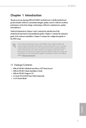
... of the software and utilities. In case any modifications of this documentation will be available on ASRock's website as well. ASRock website http://www.asrock.com. 1.1 Package Contents • ASRock H110M-I Motherboard (Micro ATX Form Factor) • ASRock H110M-I Quick Installation Guide • ASRock H110M-I Support CD • 2 x Serial ATA (SATA) Data Cables (Optional) • 1 x I/O Panel Shield 1 English Chapter 4 contains...
... of the software and utilities. In case any modifications of this documentation will be available on ASRock's website as well. ASRock website http://www.asrock.com. 1.1 Package Contents • ASRock H110M-I Motherboard (Micro ATX Form Factor) • ASRock H110M-I Quick Installation Guide • ASRock H110M-I Support CD • 2 x Serial ATA (SATA) Data Cables (Optional) • 1 x I/O Panel Shield 1 English Chapter 4 contains...

User Manual
Page 9
1.3 Motherboard Layout 1 2 PS 2 Mouse PS2 Keyboard ATX12V1 CPU_FAN1 H110M-I 3 4 CHA_FAN1 DVI1 DDR4_A1 (64 bit, 288-pin module) DDR4_B1 (64 bit,288-pin module) ATXPWR1 5 USB 3.0 T: USB1 B: USB2 USB 2.0 T: USB0 B: USB1 USB 2.0 T: USB2 B: USB3 Top: RJ-45 RoHS SATA3_3 SATA3_2 SATA3_1 SATA3_0 USB3_3_4 1 Intel CMOS Battery Top: LINE IN Center: FRONT Bottom: MIC IN 6 1 H110 HD_AUDIO1 16 7 Audio CODEC 1 PANEL1 SPK_CI1 USB_4_5 PLED PWRBTN HDLED RESET PCIE1 1 1 8 BIOS ROM H110M-I 1 TPMS1 9 PCIE2 CLRMOS1 15 14 13 12 11 10 English 5
1.3 Motherboard Layout 1 2 PS 2 Mouse PS2 Keyboard ATX12V1 CPU_FAN1 H110M-I 3 4 CHA_FAN1 DVI1 DDR4_A1 (64 bit, 288-pin module) DDR4_B1 (64 bit,288-pin module) ATXPWR1 5 USB 3.0 T: USB1 B: USB2 USB 2.0 T: USB0 B: USB1 USB 2.0 T: USB2 B: USB3 Top: RJ-45 RoHS SATA3_3 SATA3_2 SATA3_1 SATA3_0 USB3_3_4 1 Intel CMOS Battery Top: LINE IN Center: FRONT Bottom: MIC IN 6 1 H110 HD_AUDIO1 16 7 Audio CODEC 1 PANEL1 SPK_CI1 USB_4_5 PLED PWRBTN HDLED RESET PCIE1 1 1 8 BIOS ROM H110M-I 1 TPMS1 9 PCIE2 CLRMOS1 15 14 13 12 11 10 English 5

User Manual
Page 13
.... Failure to the chassis, please do so may damage the motherboard. 9 English H110M-I Chapter 2 Installation This is a Micro ATX form factor motherboard. Doing so may cause physical injuries and damages to motherboard components. • In order to avoid damage from static electricity to the motherboard's components, NEVER place your chassis to ensure that comes with...
.... Failure to the chassis, please do so may damage the motherboard. 9 English H110M-I Chapter 2 Installation This is a Micro ATX form factor motherboard. Doing so may cause physical injuries and damages to motherboard components. • In order to avoid damage from static electricity to the motherboard's components, NEVER place your chassis to ensure that comes with...

User Manual
Page 16
The cover must be placed if you wish to return the motherboard for after service. 12 English Please save and replace the cover if the processor is removed.
The cover must be placed if you wish to return the motherboard for after service. 12 English Please save and replace the cover if the processor is removed.

User Manual
Page 18
It will cause permanent damage to the motherboard and the DIMM if you always need to install identical (the same brand, speed, size and chip-type) DDR4 DIMM pairs. 2. It is not allowed ... module into the slot at incorrect orientation. 14 English For dual channel configuration, you force the DIMM into a DDR4 slot; 2.3 Installing Memory Modules (DIMM) This motherboard provides two 288-pin DDR4 (Double Data Rate 4) DIMM slots, and supports Dual Channel Memory Technology. 1. otherwise, this...
It will cause permanent damage to the motherboard and the DIMM if you always need to install identical (the same brand, speed, size and chip-type) DDR4 DIMM pairs. 2. It is not allowed ... module into the slot at incorrect orientation. 14 English For dual channel configuration, you force the DIMM into a DDR4 slot; 2.3 Installing Memory Modules (DIMM) This motherboard provides two 288-pin DDR4 (Double Data Rate 4) DIMM slots, and supports Dual Channel Memory Technology. 1. otherwise, this...

User Manual
Page 20
Before installing an expansion card, please make necessary hardware settings for PCI Express x16 lane width graphics cards. 16 English PCIe slots: PCIE1 (PCIe 2.0 x1 slot) is used for PCI Express x1 lane width cards PCIE2 (PCIe 3.0 x16 slot) is unplugged. Please read the documentation of the expansion card and make sure that the power supply is switched off or the power cord is used for the card before you start the installation. 2.4 Expansion Slots (PCI Express Slots) There are 2 PCI Express slots on the motherboard.
Before installing an expansion card, please make necessary hardware settings for PCI Express x16 lane width graphics cards. 16 English PCIe slots: PCIE1 (PCIe 2.0 x1 slot) is used for PCI Express x1 lane width cards PCIE2 (PCIe 3.0 x16 slot) is unplugged. Please read the documentation of the expansion card and make sure that the power supply is switched off or the power cord is used for the card before you start the installation. 2.4 Expansion Slots (PCI Express Slots) There are 2 PCI Express slots on the motherboard.

User Manual
Page 21
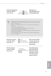
...on the chassis front panel. RESET (Reset Switch): Connect to this header, make sure the wire assignments and the pin assignments are NOT jumpers. H110M-I 2.5 Onboard Headers and Connectors Onboard headers and connectors are matched correctly. System Panel Header (9-pin PANEL1) (see p.5, No. 11) GND ...the power switch on the chassis front panel. Press the reset switch to restart the computer if the computer freezes and fails to the motherboard. The front panel design may configure the way to turn off (S5). PWRBTN (Power Switch): Connect to the pin 1 assignments ...
...on the chassis front panel. RESET (Reset Switch): Connect to this header, make sure the wire assignments and the pin assignments are NOT jumpers. H110M-I 2.5 Onboard Headers and Connectors Onboard headers and connectors are matched correctly. System Panel Header (9-pin PANEL1) (see p.5, No. 11) GND ...the power switch on the chassis front panel. Press the reset switch to restart the computer if the computer freezes and fails to the motherboard. The front panel design may configure the way to turn off (S5). PWRBTN (Power Switch): Connect to the pin 1 assignments ...

User Manual
Page 22
... up to this IntA_PB_SSTX- USB 3.0 Header (19-pin USB3_3_4) (see p.5, No. 6) Vbus IntA_PA_SSRXIntA_PA_SSRX+ GND IntA_PA_SSTXIntA_PA_SSTX+ GND IntA_PA_DIntA_PA_D+ Besides two USB 3.0 ports Vbus IntA_PB_SSRX- IntA_PB_SSTX+ motherboard. Each USB GND IntA_PB_DIntA_PB_D+ Dummy 3.0 header can support two ports. Chassis Intrusion and Speaker Header (7-pin SPK_CI1) (see p.5, No. 12) 1 SIGNAL GND DUMMY Please connect... transfer rate. 1 USB_PWR PP+ GND USB_PWR PP+ GND DUMMY Besides four USB 2.0 ports on the I /O panel, there IntA_PB_SSRX+ GND is one header on this motherboard.
... up to this IntA_PB_SSTX- USB 3.0 Header (19-pin USB3_3_4) (see p.5, No. 6) Vbus IntA_PA_SSRXIntA_PA_SSRX+ GND IntA_PA_SSTXIntA_PA_SSTX+ GND IntA_PA_DIntA_PA_D+ Besides two USB 3.0 ports Vbus IntA_PB_SSRX- IntA_PB_SSTX+ motherboard. Each USB GND IntA_PB_DIntA_PB_D+ Dummy 3.0 header can support two ports. Chassis Intrusion and Speaker Header (7-pin SPK_CI1) (see p.5, No. 12) 1 SIGNAL GND DUMMY Please connect... transfer rate. 1 USB_PWR PP+ GND USB_PWR PP+ GND DUMMY Besides four USB 2.0 ports on the I /O panel, there IntA_PB_SSRX+ GND is one header on this motherboard.
User Manual
Page 23
...: A. C. MIC_RET and OUT_RET are for the AC'97 audio panel. You don't need to MIC2_L. Chassis Fan Connector (4-pin CHA_FAN1) (see p.5, No. 2) This motherboard pro- English 19 H110M-I Front Panel Audio Header (9-pin HD_AUDIO1) (see p.5, No. 16) OUT_RET MIC_RET PRESENCE# GN D This header is for OUT2_L J_SENSE connecting audio devices OUT2_R MIC2_R...
...: A. C. MIC_RET and OUT_RET are for the AC'97 audio panel. You don't need to MIC2_L. Chassis Fan Connector (4-pin CHA_FAN1) (see p.5, No. 2) This motherboard pro- English 19 H110M-I Front Panel Audio Header (9-pin HD_AUDIO1) (see p.5, No. 16) OUT_RET MIC_RET PRESENCE# GN D This header is for OUT2_L J_SENSE connecting audio devices OUT2_R MIC2_R...

User Manual
Page 24
..., take out the CMOS battery and short the Clear CMOS Pad. Clear CMOS Pad (CLRMOS1) (see p.5, No. 5) 1 13 12 24 This motherboard provides a 24-pin ATX power connector. ATX Power Connector (24-pin ATXPWR1) (see p.5, No. 10) CLRMOS1 allows you to clear the data ...in CMOS. ATX 12V Power Connector (8-pin ATX12V1) (see p.5, No. 1) TPM Header (17-pin TPMS1) (see p.5, No. 8) 5 1 8 4 This motherboard provides a 8-pin ATX 12V power connector. 1 PCICLK FRAME PCIRST# LAD3 +3V LAD0 +3VSB GND This connector supports Trusted GND SMB_CLK_MAIN Platform Module (TPM) system, SMB_DATA_MAIN...
..., take out the CMOS battery and short the Clear CMOS Pad. Clear CMOS Pad (CLRMOS1) (see p.5, No. 5) 1 13 12 24 This motherboard provides a 24-pin ATX power connector. ATX Power Connector (24-pin ATXPWR1) (see p.5, No. 10) CLRMOS1 allows you to clear the data ...in CMOS. ATX 12V Power Connector (8-pin ATX12V1) (see p.5, No. 1) TPM Header (17-pin TPMS1) (see p.5, No. 8) 5 1 8 4 This motherboard provides a 8-pin ATX 12V power connector. 1 PCICLK FRAME PCIRST# LAD3 +3V LAD0 +3VSB GND This connector supports Trusted GND SMB_CLK_MAIN Platform Module (TPM) system, SMB_DATA_MAIN...

User Manual
Page 25
...support.microsoft.com/kb/2720599/en-us 21 English H110M-I Chapter 3 Software and Utilities Operation 3.1 Installing Drivers The Support CD that comes with the motherboard contains necessary drivers and useful utilities that the motherboard supports. Utilities Menu The Utilities Menu shows the... application software that enhance the motherboard's features. Running The Support CD To begin using the...
...support.microsoft.com/kb/2720599/en-us 21 English H110M-I Chapter 3 Software and Utilities Operation 3.1 Installing Drivers The Support CD that comes with the motherboard contains necessary drivers and useful utilities that the motherboard supports. Utilities Menu The Utilities Menu shows the... application software that enhance the motherboard's features. Running The Support CD To begin using the...

User Manual
Page 26
... English Information Panel: The information panel in the center displays data about the currently selected category and allows users to download apps from the ASRock Live Update & APP Shop. 3.2.1 UI Overview Category Panel Hot News Information Panel Category Panel: The category panel contains several category tabs or... buttons that when selected the information panel below displays the relative information. Double-click utility. Click on your motherboard up to visit the website of the selected news and know more . You can optimize your system and keep your desktop to access...
... English Information Panel: The information panel in the center displays data about the currently selected category and allows users to download apps from the ASRock Live Update & APP Shop. 3.2.1 UI Overview Category Panel Hot News Information Panel Category Panel: The category panel contains several category tabs or... buttons that when selected the information panel below displays the relative information. Double-click utility. Click on your motherboard up to visit the website of the selected news and know more . You can optimize your system and keep your desktop to access...

User Manual
Page 32
... the Enhanced Host Controller Interface (EHCI - 3.3 Enabling USB Ports for Windows® 7 Installation Intel® Braswell and Skylake has removed their motherboard won't work. Due to that fact that XHCI is not included in UEFI SETUP UTILITY > Advanced > USB Configuration, which allows the USB ...; A Windows® 7 installation disk or USB drive • USB 3.0 drivers (included in the ASRock Support CD or website) • A Windows® PC • Win7 USB Patcher (included in the ASRock Support CD or website) Scenarios You have an ODD (For Intel Skylake platforms only): If there is an...
... the Enhanced Host Controller Interface (EHCI - 3.3 Enabling USB Ports for Windows® 7 Installation Intel® Braswell and Skylake has removed their motherboard won't work. Due to that fact that XHCI is not included in UEFI SETUP UTILITY > Advanced > USB Configuration, which allows the USB ...; A Windows® 7 installation disk or USB drive • USB 3.0 drivers (included in the ASRock Support CD or website) • A Windows® PC • Win7 USB Patcher (included in the ASRock Support CD or website) Scenarios You have an ODD (For Intel Skylake platforms only): If there is an...

User Manual
Page 41
... DRAM Frequency If [Auto] is exceeded, the CPU ratio will detect the memory module(s) inserted and assign the appropriate frequency automatically. H110M-I Long Duration Maintained Configure the period of clock cycles required between a bank active command and issuing the precharge command. DRAM Configuration DRAM...tCL) The time between the opening the next row. A lower limit can be lowered immediately. When the limit is selected, the motherboard will be issued. 37 English Row Precharge: The number of time until the CPU ratio is lowered when the Long Duration Power Limit ...
... DRAM Frequency If [Auto] is exceeded, the CPU ratio will detect the memory module(s) inserted and assign the appropriate frequency automatically. H110M-I Long Duration Maintained Configure the period of clock cycles required between a bank active command and issuing the precharge command. DRAM Configuration DRAM...tCL) The time between the opening the next row. A lower limit can be lowered immediately. When the limit is selected, the motherboard will be issued. 37 English Row Precharge: The number of time until the CPU ratio is lowered when the Long Duration Power Limit ...

User Manual
Page 61
H110M-I 4.8 Hardware Health Event Monitoring Screen This section allows you to set 5 CPU temperatures and assign a respective fan speed for each temperature. Chassis Fan 1 Setting Select a ... temperatures and assign a respective fan speed for each temperature. Over Temperature Protection When Over Temperature Protection is enabled, the system automatically shuts down when the motherboard is overheated. 57 English Chassis Fan 1 Temp Source Select a fan temperature source for CPU Fans, or choose Customize to monitor the status of the hardware...
H110M-I 4.8 Hardware Health Event Monitoring Screen This section allows you to set 5 CPU temperatures and assign a respective fan speed for each temperature. Chassis Fan 1 Setting Select a ... temperatures and assign a respective fan speed for each temperature. Over Temperature Protection When Over Temperature Protection is enabled, the system automatically shuts down when the motherboard is overheated. 57 English Chassis Fan 1 Temp Source Select a fan temperature source for CPU Fans, or choose Customize to monitor the status of the hardware...

