User Manual
Page 3
... Guide 29 2.11 Serial ATA (SATA) / Serial ATAII (SATAII) Hard Disks Installation 30 2.12 Driver Installation Guide 30 2.13 Untied Overclocking Technology 30 3 BIOS SETUP UTILITY 31 3.1 Introduction 31 3.1.1 BIOS Menu Bar 31 3.1.2 Navigation Keys 32 3.2 Main Screen 32 3.3 Smart Screen 33 3.4 Advanced Screen 34 3.4.1 CPU Configuration 35 3.4.2 Chipset Configuration 37 3.4.3 ACPI...
... Guide 29 2.11 Serial ATA (SATA) / Serial ATAII (SATAII) Hard Disks Installation 30 2.12 Driver Installation Guide 30 2.13 Untied Overclocking Technology 30 3 BIOS SETUP UTILITY 31 3.1 Introduction 31 3.1.1 BIOS Menu Bar 31 3.1.2 Navigation Keys 32 3.2 Main Screen 32 3.3 Smart Screen 33 3.4 Advanced Screen 34 3.4.1 CPU Configuration 35 3.4.2 Chipset Configuration 37 3.4.3 ACPI...
User Manual
Page 5
... step-by-step guide to quality and endurance. ASRock website http://www.asrock.com If you require technical support related to BIOS setup and information of this motherboard, please visit our website for specific information about the model you for purchasing ASRock G41MH-GE motherboard, a reliable motherboard produced under ASRock's consistently stringent quality control. It delivers excellent...
... step-by-step guide to quality and endurance. ASRock website http://www.asrock.com If you require technical support related to BIOS setup and information of this motherboard, please visit our website for specific information about the model you for purchasing ASRock G41MH-GE motherboard, a reliable motherboard produced under ASRock's consistently stringent quality control. It delivers excellent...
User Manual
Page 7
...Chassis/Power FAN connector - 24 pin ATX power connector - 4 pin 12V power connector - AMI Legal BIOS - ASRock OC Tuner (see CAUTION 14) - ASRock OC DNA (see CAUTION 11) - Boot Failure Guard (B.F.G.) - CD in /Front Speaker/Microphone (see ...USB 2.0 ports) (see CAUTION 16) - ASRock U-COP (see CAUTION 10) - 8Mb AMI BIOS - Supports "Plug and Play" - ACPI 1.1 Compliance Wake Up Events - T. (Intelligent Overclocking Technology) - Supports Smart BIOS - CPU Frequency Stepless Control (see CAUTION 13) - Supports jumperfree - ASRock Instant Flash (see CAUTION 15) - Intelligent ...
...Chassis/Power FAN connector - 24 pin ATX power connector - 4 pin 12V power connector - AMI Legal BIOS - ASRock OC Tuner (see CAUTION 14) - ASRock OC DNA (see CAUTION 11) - Boot Failure Guard (B.F.G.) - CD in /Front Speaker/Microphone (see ...USB 2.0 ports) (see CAUTION 16) - ASRock U-COP (see CAUTION 10) - 8Mb AMI BIOS - Supports "Plug and Play" - ACPI 1.1 Compliance Wake Up Events - T. (Intelligent Overclocking Technology) - Supports Smart BIOS - CPU Frequency Stepless Control (see CAUTION 13) - Supports jumperfree - ASRock Instant Flash (see CAUTION 15) - Intelligent ...

User Manual
Page 8
...our lab test. 8 For Windows® XP 64-bit and Windows® VistaTM 64-bit with overclocking, including adjusting the setting in the BIOS, applying Untied Overclocking Technology, or using the thirdparty overclocking tools. Full HD 1080p Blu-ray (BD) / HD-DVD playback support requires the proper..., WHQL - EuP Ready (EuP ready power supply is required) (see CAUTION 17) * For detailed product information, please visit our website: http://www.asrock.com WARNING Please realize that there is a certain risk involved with 64-bit CPU, there is subject to page 10 for details. 3. We are not...
...our lab test. 8 For Windows® XP 64-bit and Windows® VistaTM 64-bit with overclocking, including adjusting the setting in the BIOS, applying Untied Overclocking Technology, or using the thirdparty overclocking tools. Full HD 1080p Blu-ray (BD) / HD-DVD playback support requires the proper..., WHQL - EuP Ready (EuP ready power supply is required) (see CAUTION 17) * For detailed product information, please visit our website: http://www.asrock.com WARNING Please realize that there is a certain risk involved with 64-bit CPU, there is subject to page 10 for details. 3. We are not...
User Manual
Page 9
... the OC profile can load the OC profile to their own system to access ASRock Instant Flash. ASRock website: http://www.asrock.com 12. The software name itself - It helps you to save the new BIOS file to your friends! Please check the table on the same motherboard. 15.... You can update your system by ASRock, provides a convenient way for the operation procedures of Intelligent Energy Saver. This convenient BIOS update tool allows you to surveil your BIOS only in Flash ROM. In other than the recommended CPU bus frequencies may...
... the OC profile can load the OC profile to their own system to access ASRock Instant Flash. ASRock website: http://www.asrock.com 12. The software name itself - It helps you to save the new BIOS file to your friends! Please check the table on the same motherboard. 15.... You can update your system by ASRock, provides a convenient way for the operation procedures of Intelligent Energy Saver. This convenient BIOS update tool allows you to surveil your BIOS only in Flash ROM. In other than the recommended CPU bus frequencies may...

User Manual
Page 11
...(64 bit, 240-pin module) DDRII_1 (64 bit, 240-pin module) RoHS FSB1333 HDMI1 SPDIF_O1 30 1 IR1 USB 2.0 T: USB2 B: USB3 PWR_FAN1 IDE1 G41MH-GE USB 2.0 T: USB0 B: USB1 Top: RJ-45 Top: SIDE SPK Center: REAR SPK Bottom: CTR BASS Top: LINE IN Center: FRONT Bottom: MIC IN... PHY DX10 29 28 PCIE1 Intel G41 Chipset Super I/O 27 26 AUDIO CODEC CD1 HD_AUDIO1 1 FLOPPY1 PCIE2 PCI1 PCI2 1 COM1 LPT1 1 8Mb BIOS SPEAKER1 CMOS Battery 1 PLED PWRBTN CLRCMOS1 PANEL1 1 1 HDLED RESET CHA_FAN1 USB4_5 USB6_7 1 1 Intel ICH7 SATAII_1 SATAII_2 SATAII_3 SATAII_4 25 24 23 ...
...(64 bit, 240-pin module) DDRII_1 (64 bit, 240-pin module) RoHS FSB1333 HDMI1 SPDIF_O1 30 1 IR1 USB 2.0 T: USB2 B: USB3 PWR_FAN1 IDE1 G41MH-GE USB 2.0 T: USB0 B: USB1 Top: RJ-45 Top: SIDE SPK Center: REAR SPK Bottom: CTR BASS Top: LINE IN Center: FRONT Bottom: MIC IN... PHY DX10 29 28 PCIE1 Intel G41 Chipset Super I/O 27 26 AUDIO CODEC CD1 HD_AUDIO1 1 FLOPPY1 PCIE2 PCI1 PCI2 1 COM1 LPT1 1 8Mb BIOS SPEAKER1 CMOS Battery 1 PLED PWRBTN CLRCMOS1 PANEL1 1 1 HDLED RESET CHA_FAN1 USB4_5 USB6_7 1 1 Intel ICH7 SATAII_1 SATAII_2 SATAII_3 SATAII_4 25 24 23 ...
User Manual
Page 27
... AC'97 audio panel, please install it to connect them for HD audio panel only. MIC_RET and OUT_RET are for AC'97 audio panel. E. Enter BIOS Setup Utility. Enter Advanced Settings, and then select Chipset Configuration. Connect Audio_R (RIN) to OUT2_R and Audio_L (LIN) to the ground pin. D. System Panel Header...
... AC'97 audio panel, please install it to connect them for HD audio panel only. MIC_RET and OUT_RET are for AC'97 audio panel. E. Enter BIOS Setup Utility. Enter Advanced Settings, and then select Chipset Configuration. Connect Audio_R (RIN) to OUT2_R and Audio_L (LIN) to the ground pin. D. System Panel Header...
User Manual
Page 30
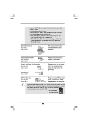
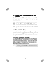
STEP 2: Connect the SATA power cable to install the SATA / SATAII hard disks. STEP 4: Connect the other end of BIOS setup to set the selection from up to bottom side to install those required drivers. Please refer to [Manual]. Please follow the order from [Auto] ...
STEP 2: Connect the SATA power cable to install the SATA / SATAII hard disks. STEP 4: Connect the other end of BIOS setup to set the selection from up to bottom side to install those required drivers. Please refer to [Manual]. Please follow the order from [Auto] ...

User Manual
Page 31
... following selections: Main To set up the security features Exit To exit the current screen or the BIOS SETUP UTILITY Use < > key or < > key to choose among the selections on the menu...press or during the Power-On-Self-Test (POST) to enter the BIOS SETUP UTILITY, otherwise, POST will continue with the following BIOS setup screens and descriptions are for reference purpose only, and they may ...on the system chassis. If you start up the computer. You may run the BIOS SETUP UTILITY when you wish to enter the BIOS SETUP UTILITY after POST, restart the system by pressing + + , or by...
... following selections: Main To set up the security features Exit To exit the current screen or the BIOS SETUP UTILITY Use < > key or < > key to choose among the selections on the menu...press or during the Power-On-Self-Test (POST) to enter the BIOS SETUP UTILITY, otherwise, POST will continue with the following BIOS setup screens and descriptions are for reference purpose only, and they may ...on the system chassis. If you start up the computer. You may run the BIOS SETUP UTILITY when you wish to enter the BIOS SETUP UTILITY after POST, restart the system by pressing + + , or by...

User Manual
Page 32
... Main Smart Advanced H/W Monitor Boot Security Exit System Overview System Time System Date [14:00:09] [Mon 09/21/2008] BIOS Version : G41MH-GE P1.00 Processor Type : Intel(R) CPU 3.20GHz (64bit) Processor Speed : 3200MHz Microcode Update : F64/4 Cache Size : 4096KB Total Memory DDRII1 DDRII2 DDRII3 ... None : None Use [Enter], [TAB] or [SHIFT-TAB] to the Exit Screen or exit the current screen 3.2 Main Screen When you enter the BIOS SETUP UTILITY, the Main screen will appear and display the system overview. System Date [Day Month/Date/Year] Use this item to specify the system...
... Main Smart Advanced H/W Monitor Boot Security Exit System Overview System Time System Date [14:00:09] [Mon 09/21/2008] BIOS Version : G41MH-GE P1.00 Processor Type : Intel(R) CPU 3.20GHz (64bit) Processor Speed : 3200MHz Microcode Update : F64/4 Cache Size : 4096KB Total Memory DDRII1 DDRII2 DDRII3 ... None : None Use [Enter], [TAB] or [SHIFT-TAB] to the Exit Screen or exit the current screen 3.2 Main Screen When you enter the BIOS SETUP UTILITY, the Main screen will appear and display the system overview. System Date [Day Month/Date/Year] Use this item to specify the system...

User Manual
Page 33
...H/W Monitor Boot Security Exit Smart Settings Save Changes and Exit Load BIOS Defaults Load Performance Setup Default (IDE/SATA) Load Power Saving Setup Default BIOS Update Utility ASRock Instant Flash Exit system setup after BIOS update process completes. 33 Load Power Saving Setup Default Load power saving...use FAT32/16/ 12 file system. If system boot failure occurs after loading, please resume optimal default settings. ASRock Instant Flash ASRock Instant Flash is a BIOS flash utility embedded in a few clicks without entering operating systems first like MS-DOS or Windows®.
...H/W Monitor Boot Security Exit Smart Settings Save Changes and Exit Load BIOS Defaults Load Performance Setup Default (IDE/SATA) Load Power Saving Setup Default BIOS Update Utility ASRock Instant Flash Exit system setup after BIOS update process completes. 33 Load Power Saving Setup Default Load power saving...use FAT32/16/ 12 file system. If system boot failure occurs after loading, please resume optimal default settings. ASRock Instant Flash ASRock Instant Flash is a BIOS flash utility embedded in a few clicks without entering operating systems first like MS-DOS or Windows®.
User Manual
Page 34
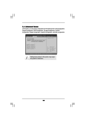
... CPU Configuration Chipset Configuration ACPI Configuration Storage Configuration PCIPnP Configuration Floppy Configuration SuperIO Configuration USB Configuration Select Screen Select Item Enter Go to malfunction. 34 BIOS SETUP UTILITY Main Smart Advanced H/W Monitor Boot Security Exit Advanced Settings WARNING : Setting wrong values in this section, you may cause the system to Sub...
... CPU Configuration Chipset Configuration ACPI Configuration Storage Configuration PCIPnP Configuration Floppy Configuration SuperIO Configuration USB Configuration Select Screen Select Item Enter Go to malfunction. 34 BIOS SETUP UTILITY Main Smart Advanced H/W Monitor Boot Security Exit Advanced Settings WARNING : Setting wrong values in this section, you may cause the system to Sub...
User Manual
Page 35
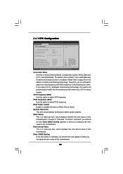
... item Ratio CMOS Setting appears to adjust the Host frequency and PCIE frequency in the following two items. If you select [I .O.T.] and [Optimized]. 3.4.1 CPU Configuration BIOS SETUP UTILITY Advanced CPU Configuration Overclock Mode CPU Frequency (MHz) PCIE Frequency (MHz) Boot Failure Guard Spread Spectrum [Auto] [200] [100] [Enabled] [Auto] Ratio Status...
... item Ratio CMOS Setting appears to adjust the Host frequency and PCIE frequency in the following two items. If you select [I .O.T.] and [Optimized]. 3.4.1 CPU Configuration BIOS SETUP UTILITY Advanced CPU Configuration Overclock Mode CPU Frequency (MHz) PCIE Frequency (MHz) Boot Failure Guard Spread Spectrum [Auto] [200] [100] [Enabled] [Auto] Ratio Status...
User Manual
Page 37
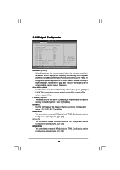
... This controls the number of DRAM clocks for TRAS. Strap FSB to MCH. Configuration options: [Auto], [1066] and [1333]. Configuration options: [3], [4], [5], [6], [7] and [Auto]. 3.4.2 Chipset Configuration BIOS SETUP UTILITY Advanced Chipset Settings DRAM Frequency [Auto] Strap FSB to [10]. It will detect the memory module(s) inserted and assigns appropriate frequency automatically. DRAM...
... This controls the number of DRAM clocks for TRAS. Strap FSB to MCH. Configuration options: [Auto], [1066] and [1333]. Configuration options: [3], [4], [5], [6], [7] and [Auto]. 3.4.2 Chipset Configuration BIOS SETUP UTILITY Advanced Chipset Settings DRAM Frequency [Auto] Strap FSB to [10]. It will detect the memory module(s) inserted and assigns appropriate frequency automatically. DRAM...

User Manual
Page 39
...]. The default value is [Auto]. DRAM CH0 G5 (Clocks2) This controls the number of DRAM CH0 G1 (Command). Max: 15. Min: 1. DRAM RCOMP STRENGTH Configuration BIOS SETUP UTILITY Advanced DRAM RCOMP STRENGTH Settings DRAM CH0 RCOMP STRENGTH Info : 0-10-7-7-7-7 DRAM CH0 G0 (Data) [Auto] DRAM CH0 G1 (Command) [Auto] DRAM CH0...
...]. The default value is [Auto]. DRAM CH0 G5 (Clocks2) This controls the number of DRAM CH0 G1 (Command). Max: 15. Min: 1. DRAM RCOMP STRENGTH Configuration BIOS SETUP UTILITY Advanced DRAM RCOMP STRENGTH Settings DRAM CH0 RCOMP STRENGTH Info : 0-10-7-7-7-7 DRAM CH0 G0 (Data) [Auto] DRAM CH0 G1 (Command) [Auto] DRAM CH0...

User Manual
Page 41
... value is [Auto]. DRAM CH0 CTRL3 SKEW This controls the number of DRAM CH0 CTRL3 SKEW. The default value is [Auto]. DRAM DLL SKEW Settings BIOS SETUP UTILITY Advanced DRAM DLL SKEW Settings DRAM CH0 CLKSET0 SKEW Info:0-0-0-0-0-0 DRAM CH0 CLKSET0 SKEW [Auto] DRAM CH0 CLKSET1 SKEW Info:0-0-0-0-0-0 DRAM CH0 CLKSET1...
... value is [Auto]. DRAM CH0 CTRL3 SKEW This controls the number of DRAM CH0 CTRL3 SKEW. The default value is [Auto]. DRAM DLL SKEW Settings BIOS SETUP UTILITY Advanced DRAM DLL SKEW Settings DRAM CH0 CLKSET0 SKEW Info:0-0-0-0-0-0 DRAM CH0 CLKSET0 SKEW [Auto] DRAM CH0 CLKSET1 SKEW Info:0-0-0-0-0-0 DRAM CH0 CLKSET1...

User Manual
Page 44
If you can also choose our Intelligent Energy Saver utility to enable this function. 44 VTT Voltage Use this to select GLTREF Voltage. Besides the BIOS option, you want to enable this function, please set this item to [1.45V]. GLTREF Voltage Use this to select VTT Voltage. Configuration options: [Auto], [1.046V] ...
If you can also choose our Intelligent Energy Saver utility to enable this function. 44 VTT Voltage Use this to select GLTREF Voltage. Besides the BIOS option, you want to enable this function, please set this item to [1.45V]. GLTREF Voltage Use this to select VTT Voltage. Configuration options: [Auto], [1.046V] ...

User Manual
Page 45
... Resume" will enable this item to enable or disable RTC (Real Time Clock) to [Disabled], the function "Repost Video on the system. 45 3.4.3 ACPI Configuration BIOS SETUP UTILITY Advanced ACPI Configuration Suspend To RAM Repost Video on STR Resume Check Ready Bit Restore on the system from the power-soft-off...
... Resume" will enable this item to enable or disable RTC (Real Time Clock) to [Disabled], the function "Repost Video on the system. 45 3.4.3 ACPI Configuration BIOS SETUP UTILITY Advanced ACPI Configuration Suspend To RAM Repost Video on STR Resume Check Ready Bit Restore on the system from the power-soft-off...

User Manual
Page 47
... have to choose [SATA 1, SATA 2, SATA 3, SATA 4], [SATA 1, SATA 3, IDE 1], or [IDE 1, SATA 2, SATA 4] when the installed device is installed, please select [Enhanced]. 3.4.4 Storage Configuration BIOS SETUP UTILITY Advanced Storage Configuration ATA/IDE Configuration SATAII_1 SATAII_2 SATAII_3 SATAII_4 IDE1 Master IDE1 Slave [Enhanced] [Hard Disk] [Not Detected] [Not Detected] [Not Detected...
... have to choose [SATA 1, SATA 2, SATA 3, SATA 4], [SATA 1, SATA 3, IDE 1], or [IDE 1, SATA 2, SATA 4] when the installed device is installed, please select [Enhanced]. 3.4.4 Storage Configuration BIOS SETUP UTILITY Advanced Storage Configuration ATA/IDE Configuration SATAII_1 SATAII_2 SATAII_3 SATAII_4 IDE1 Master IDE1 Slave [Enhanced] [Hard Disk] [Not Detected] [Not Detected] [Not Detected...

User Manual
Page 48
..., American Megatrends, Inc. PIO Mode Use this item to partition and format the new IDE hard disk drives. After selecting the hard disk information into BIOS, use of the IDE device that you specify. for IDE ARMD (ATAPI Removable Media Device), such as FDISK, to select the LBA/Large mode for.../DVD]: This is used for IDE CD/DVD drives. [ARMD]: This is enabled, it will enhance hard disk performance by optimizing the hard disk timing. BIOS SETUP UTILITY Advanced Primary IDE Master Device Vendor Size LBA Mode Block Mode PIO Mode Async DMA Ultra DMA S.M.A.R.T.
..., American Megatrends, Inc. PIO Mode Use this item to partition and format the new IDE hard disk drives. After selecting the hard disk information into BIOS, use of the IDE device that you specify. for IDE ARMD (ATAPI Removable Media Device), such as FDISK, to select the LBA/Large mode for.../DVD]: This is used for IDE CD/DVD drives. [ARMD]: This is enabled, it will enhance hard disk performance by optimizing the hard disk timing. BIOS SETUP UTILITY Advanced Primary IDE Master Device Vendor Size LBA Mode Block Mode PIO Mode Async DMA Ultra DMA S.M.A.R.T.


