
User Manual
Page 2
... or copyrights of their respective companies, and are furnished for informational use only and subject to the contents of documentation by ASRock. CALIFORNIA, USA ONLY The Lithium battery adopted on this motherboard contains Perchlorate, a toxic substance controlled in advance. Operation is subject to the implied warranties or conditions of merchantability or fitness...
... or copyrights of their respective companies, and are furnished for informational use only and subject to the contents of documentation by ASRock. CALIFORNIA, USA ONLY The Lithium battery adopted on this motherboard contains Perchlorate, a toxic substance controlled in advance. Operation is subject to the implied warranties or conditions of merchantability or fitness...

User Manual
Page 3
Contents 1 Introduction 5 1.1 Package Contents 5 1.2 Specifications 6 1.3 Motherboard Layout 11 1.4 I/O Panel 12 2 Installation 13 2.1 Screw Holes 13 2.2 Pre-installation Precautions 13 2.3 CPU Installation 14 2.4 Installation of Heatsink and CPU fan 16 2.5 Installation of ...
Contents 1 Introduction 5 1.1 Package Contents 5 1.2 Specifications 6 1.3 Motherboard Layout 11 1.4 I/O Panel 12 2 Installation 13 2.1 Screw Holes 13 2.2 Pre-installation Precautions 13 2.3 CPU Installation 14 2.4 Installation of Heatsink and CPU fan 16 2.5 Installation of ...

User Manual
Page 5
...ASRock website http://www.asrock.com If you require technical support related to the hardware installation. www.asrock.com/support/index.asp 1.1 Package Contents ASRock G41M-GE3 Motherboard (Micro ATX Form Factor: 9.6-in x 8.6-in, 24.4 cm x 21.8 cm) ASRock G41M-GE3 Quick Installation Guide ASRock G41M-GE3... and endurance. In case any modifications of this motherboard, please visit our website for specific information about the model you for purchasing ASRock G41M-GE3 motherboard, a reliable motherboard produced under ASRock's consistently stringent quality control. You may find the...
...ASRock website http://www.asrock.com If you require technical support related to the hardware installation. www.asrock.com/support/index.asp 1.1 Package Contents ASRock G41M-GE3 Motherboard (Micro ATX Form Factor: 9.6-in x 8.6-in, 24.4 cm x 21.8 cm) ASRock G41M-GE3 Quick Installation Guide ASRock G41M-GE3... and endurance. In case any modifications of this motherboard, please visit our website for specific information about the model you for purchasing ASRock G41M-GE3 motherboard, a reliable motherboard produced under ASRock's consistently stringent quality control. You may find the...

User Manual
Page 8
... - EuP Ready (EuP ready power supply is required) (see CAUTION 16) * For detailed product information, please visit our website: http://www.asrock.com WARNING Please realize that there is a certain risk involved with 64-bit CPU, there is no such limitation. 6. It should be less ... you use a FSB533-CPU on page 17 for possible damage caused by the chipset vendor and is defined by overclocking. CAUTION! 1. This motherboard supports Untied Overclocking Technology. CPU FSB Frequency Memory Support Frequency 1333 DDR3 800, DDR3 1066, DDR3 1333 1066 DDR3 800, DDR3 1066 800...
... - EuP Ready (EuP ready power supply is required) (see CAUTION 16) * For detailed product information, please visit our website: http://www.asrock.com WARNING Please realize that there is a certain risk involved with 64-bit CPU, there is no such limitation. 6. It should be less ... you use a FSB533-CPU on page 17 for possible damage caused by the chipset vendor and is defined by overclocking. CAUTION! 1. This motherboard supports Untied Overclocking Technology. CPU FSB Frequency Memory Support Frequency 1333 DDR3 800, DDR3 1066, DDR3 1333 1066 DDR3 800, DDR3 1066 800...

User Manual
Page 9
For audio output, this motherboard supports both stereo and mono modes. Power Management for USB 2.0 works fine under the operating system and simplifies the complicated recording process of . ASRock Instant Flash is not recommended to update system BIOS without entering operating systems first ...you to surveil your friends! In other words, it is able to access ASRock Instant Flash. This convenient BIOS update tool allows you what it is capable of overclocking settings. With this motherboard offers stepless control, it is a BIOS flash utility embedded in a few ...
For audio output, this motherboard supports both stereo and mono modes. Power Management for USB 2.0 works fine under the operating system and simplifies the complicated recording process of . ASRock Instant Flash is not recommended to update system BIOS without entering operating systems first ...you to surveil your friends! In other words, it is able to access ASRock Instant Flash. This convenient BIOS update tool allows you what it is capable of overclocking settings. With this motherboard offers stepless control, it is a BIOS flash utility embedded in a few ...

User Manual
Page 10
... with the power supply manufacturer for the completed system. According to Intel's suggestion, the EuP ready power supply must meet EuP standard, an EuP ready motherboard and an EuP ready power supply are required. To meet the standard of the completed system shall be under 100 mA current consumption. According to... consumption for more details. 10 For EuP ready power supply selection, we recommend you resume the system, please check if the CPU fan on the motherboard functions properly and unplug the power cord, then plug it back again. 15.
... with the power supply manufacturer for the completed system. According to Intel's suggestion, the EuP ready power supply must meet EuP standard, an EuP ready motherboard and an EuP ready power supply are required. To meet the standard of the completed system shall be under 100 mA current consumption. According to... consumption for more details. 10 For EuP ready power supply selection, we recommend you resume the system, please check if the CPU fan on the motherboard functions properly and unplug the power cord, then plug it back again. 15.

User Manual
Page 11
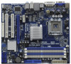
... Controller 6 2 x 240-pin DDR3 DIMM Slots 24 Serial Port Connector (COM1) (Dual Channel: DDR3_A2, DDR3_B2; 1.4 Motherboard Layout 12 3 4 21.8cm (8.6 in) 56 CPU_FAN1 PS2 Mouse PS2 Keyboard 1 PS2_USB_PWR1 VGA1 7 ATXPWR1 FSB1333 DX10 Dual Channel DDR3 1333 G41M-GE3 DDR3_A1 (64 bit, 240-pin module) DDR3_A2 (64 bit, 240-pin module) DDR3_B1 (64 bit...
... Controller 6 2 x 240-pin DDR3 DIMM Slots 24 Serial Port Connector (COM1) (Dual Channel: DDR3_A2, DDR3_B2; 1.4 Motherboard Layout 12 3 4 21.8cm (8.6 in) 56 CPU_FAN1 PS2 Mouse PS2 Keyboard 1 PS2_USB_PWR1 VGA1 7 ATXPWR1 FSB1333 DX10 Dual Channel DDR3 1333 G41M-GE3 DDR3_A1 (64 bit, 240-pin module) DDR3_A2 (64 bit, 240-pin module) DDR3_B1 (64 bit...

User Manual
Page 13
...the power is switched off or the power cord is a Micro ATX form factor (9.6" x 8.6", 24.4 x 21.8 cm) motherboard. Whenever you handle components. 3. Failure to motherboard components. 2.1 Screw Holes Place screws into it on the carpet or the like. Make sure to use a grounded wrist strap or...so may cause severe damage to the chassis. Doing so may damage the motherboard. 2.2 Pre-installation Precautions Take note of your motherboard directly on a grounded antistatic pad or in the bag that the motherboard fits into the holes indicated by the edges and do so may cause ...
...the power is switched off or the power cord is a Micro ATX form factor (9.6" x 8.6", 24.4 x 21.8 cm) motherboard. Whenever you handle components. 3. Failure to motherboard components. 2.1 Screw Holes Place screws into it on the carpet or the like. Make sure to use a grounded wrist strap or...so may cause severe damage to the chassis. Doing so may damage the motherboard. 2.2 Pre-installation Precautions Take note of your motherboard directly on a grounded antistatic pad or in the bag that the motherboard fits into the holes indicated by the edges and do so may cause ...

User Manual
Page 15
... thumb and peel the cap from the socket while pressing on load plate, engage the load lever. This cap must be placed if returning the motherboard for after service. Rotate the load plate onto the IHS. Secure load lever with load plate tab under retention tab of the socket.
... thumb and peel the cap from the socket while pressing on load plate, engage the load lever. This cap must be placed if returning the motherboard for after service. Rotate the load plate onto the IHS. Secure load lever with load plate tab under retention tab of the socket.

User Manual
Page 16
...Repeat with thumb to illustrate the installation of the heatsink for 775-LAND CPU. Before you installed the heatsink, you press down on the motherboard (CPU_FAN1, see page 11, No. 4). Then connect the CPU fan to the CPU fan connector on fastener caps with remaining fasteners. ...down the fasteners without rotating them clockwise, the heatsink cannot be secured on the motherboard. Below is equipped with each other components. 16 Step 2. 2.4 Installation of CPU Fan and Heatsink This motherboard is an example to install and lock. Ensure that supports Intel 775-LAND CPU...
...Repeat with thumb to illustrate the installation of the heatsink for 775-LAND CPU. Before you installed the heatsink, you press down on the motherboard (CPU_FAN1, see page 11, No. 4). Then connect the CPU fan to the CPU fan connector on fastener caps with remaining fasteners. ...down the fasteners without rotating them clockwise, the heatsink cannot be secured on the motherboard. Below is equipped with each other components. 16 Step 2. 2.4 Installation of CPU Fan and Heatsink This motherboard is an example to install and lock. Ensure that supports Intel 775-LAND CPU...

User Manual
Page 17
... modules, for example, installing a pair of memory modules in DDR3_A1 and DDR3_A2, it is recommended to install three or four memory modules on this motherboard, it is unable to activate the Dual Channel Memory Technology . 4. 2.5 Installation of the same color. For dual channel configuration, you have to... can only adopt four single-sided DIMMs. 17 see p.11 No.5) or identical DDR3 DIMM pair in the DDR3 DIMM slots on this motherboard and DIMM may refer to install identical (the same brand, speed, size and chiptype) DDR3 DIMM pair in the slots of white slots...
... modules, for example, installing a pair of memory modules in DDR3_A1 and DDR3_A2, it is recommended to install three or four memory modules on this motherboard, it is unable to activate the Dual Channel Memory Technology . 4. 2.5 Installation of the same color. For dual channel configuration, you have to... can only adopt four single-sided DIMMs. 17 see p.11 No.5) or identical DDR3 DIMM pair in the DDR3 DIMM slots on this motherboard and DIMM may refer to install identical (the same brand, speed, size and chiptype) DDR3 DIMM pair in the slots of white slots...

User Manual
Page 18
... 1. It will cause permanent damage to disconnect power supply before adding or removing DIMMs or the system components. Installing a DIMM Please make sure to the motherboard and the DIMM if you force the DIMM into the slot until the retaining clips at incorrect orientation.
... 1. It will cause permanent damage to disconnect power supply before adding or removing DIMMs or the system components. Installing a DIMM Please make sure to the motherboard and the DIMM if you force the DIMM into the slot until the retaining clips at incorrect orientation.

User Manual
Page 19
.... Step 2. PCIE2 (PCIE x16 slot) is used for PCI Express cards with the slot and press firmly until the card is completely seated on this motherboard. Step 4. 2.6 Expansion Slots (PCI and PCI Express Slots) There are used to install expansion cards that the power supply is switched off or the power...
.... Step 2. PCIE2 (PCIE x16 slot) is used for PCI Express cards with the slot and press firmly until the card is completely seated on this motherboard. Step 4. 2.6 Expansion Slots (PCI and PCI Express Slots) There are used to install expansion cards that the power supply is switched off or the power...

User Manual
Page 21
...-striped side to 3.0 Gb/s data transfer rate. Primary IDE connector (Blue) (39-pin IDE1, see p.11 No. 9) PIN1 IDE1 connect the blue end to the motherboard connect the black end to the IDE devices 80-conductor ATA 66/100 cable Note: Please refer to the SATA / SATAII hard disk or the... SATAII connector on this motherboard. 21 Either end of the SATA data cable can be connected to the instruction of your IDE device vendor for internal storage devices. 2.8 Onboard Headers...
...-striped side to 3.0 Gb/s data transfer rate. Primary IDE connector (Blue) (39-pin IDE1, see p.11 No. 9) PIN1 IDE1 connect the blue end to the motherboard connect the black end to the IDE devices 80-conductor ATA 66/100 cable Note: Please refer to the SATA / SATAII hard disk or the... SATAII connector on this motherboard. 21 Either end of the SATA data cable can be connected to the instruction of your IDE device vendor for internal storage devices. 2.8 Onboard Headers...

User Manual
Page 22
.... 19) 1 GND Signal Infrared Module Header (5-pin IR1) (see p.11 No. 27) IRTX +5V DUMMY 1 GND IRRX This motherboard supports CASE OPEN detection feature that allows convenient connection of printer devices. 22 Print Port Header (25-pin LPT1) (see p.11 No....P-5 P+5 GND DUMMY 1 GND P+4 P-4 USB_PWR 1 Besides four default USB 2.0 ports on the I/O panel, there are two USB 2.0 headers on this motherboard. This header supports an optional wireless transmitting and receiving infrared module. Each USB 2.0 header can securely store keys, digital certificates, passwords, and data. USB 2.0...
.... 19) 1 GND Signal Infrared Module Header (5-pin IR1) (see p.11 No. 27) IRTX +5V DUMMY 1 GND IRRX This motherboard supports CASE OPEN detection feature that allows convenient connection of printer devices. 22 Print Port Header (25-pin LPT1) (see p.11 No....P-5 P+5 GND DUMMY 1 GND P+4 P-4 USB_PWR 1 Besides four default USB 2.0 ports on the I/O panel, there are two USB 2.0 headers on this motherboard. This header supports an optional wireless transmitting and receiving infrared module. Each USB 2.0 header can securely store keys, digital certificates, passwords, and data. USB 2.0...

User Manual
Page 24
... No. 7) 12 24 Please connect an ATX power supply to this connector. 1 13 Though this motherboard provides 24-pin ATX power connector, 12 24 it can work if you plan to connect the 3-...Pin CPU fan to the CPU fan connector on this motherboard, please connect it to the ground pin. To use the 20-pin ATX power supply, ... (see p.11 No. 4) 1 GND Please connect a CPU fan cable 2 +12V 3 CPU_FAN_SPEED to this motherboard provides 4-Pin CPU fan (Quiet Fan) support, the 3-Pin CPU fan still can still work successfully even without the fan ...
... No. 7) 12 24 Please connect an ATX power supply to this connector. 1 13 Though this motherboard provides 24-pin ATX power connector, 12 24 it can work if you plan to connect the 3-...Pin CPU fan to the CPU fan connector on this motherboard, please connect it to the ground pin. To use the 20-pin ATX power supply, ... (see p.11 No. 4) 1 GND Please connect a CPU fan cable 2 +12V 3 CPU_FAN_SPEED to this motherboard provides 4-Pin CPU fan (Quiet Fan) support, the 3-Pin CPU fan still can still work successfully even without the fan ...

User Manual
Page 26
...drivers you to your optical drive first. 2 . 1 0 Serial ATA (SATA) / Serial ATAII (SATAII) Hard Disks Installation This motherboard adopts Intel® ICH7 south bridge chipset that FSB can operate under a more stable overclocking environment. This section will guide you install can... work properly. 2 . 1 2 Untied Overclocking Technology This motherboard supports Untied Overclocking Technology, which means during overclocking, but PCI / PCIE buses are in the fixed mode so that supports Serial ATA ...
...drivers you to your optical drive first. 2 . 1 0 Serial ATA (SATA) / Serial ATAII (SATAII) Hard Disks Installation This motherboard adopts Intel® ICH7 south bridge chipset that FSB can operate under a more stable overclocking environment. This section will guide you install can... work properly. 2 . 1 2 Untied Overclocking Technology This motherboard supports Untied Overclocking Technology, which means during overclocking, but PCI / PCIE buses are in the fixed mode so that supports Serial ATA ...

User Manual
Page 27
... with the following BIOS setup screens and descriptions are for reference purpose only, and they may also restart by pressing the reset button on the motherboard stores the BIOS SETUP UTILITY. If you see on your system. The SPI Memory on the system chassis.
... with the following BIOS setup screens and descriptions are for reference purpose only, and they may also restart by pressing the reset button on the motherboard stores the BIOS SETUP UTILITY. If you see on your system. The SPI Memory on the system chassis.

User Manual
Page 29
DRAM Frequency If [Auto] is [Auto]. 29 The configuration options depend on this item to strap FSB to MCH Use this motherboard. You may select [400MHz DDR3_800], [533MHz DDR3_1066] or [667MHz DDR3_1333]. Strap FSB to MCH. The configuration options depend on the ... Load Defaults F10 Save and Exit ESC Exit v02.54 (C) Copyright 1985-2005, American Megatrends, Inc. The default value is selected, the motherboard will detect the memory module(s) inserted and assigns appropriate frequency automatically. BIOS SETUP UTILITY Main OC Tweaker Advanced H/W Monitor Boot Security Exit OC ...
DRAM Frequency If [Auto] is [Auto]. 29 The configuration options depend on this item to strap FSB to MCH Use this motherboard. You may select [400MHz DDR3_800], [533MHz DDR3_1066] or [667MHz DDR3_1333]. Strap FSB to MCH. The configuration options depend on the ... Load Defaults F10 Save and Exit ESC Exit v02.54 (C) Copyright 1985-2005, American Megatrends, Inc. The default value is selected, the motherboard will detect the memory module(s) inserted and assigns appropriate frequency automatically. BIOS SETUP UTILITY Main OC Tweaker Advanced H/W Monitor Boot Security Exit OC ...

User Manual
Page 31
.... If you changing the ratio value of this option to select CPU Voltage. The default value is [Auto]. 31 CPU Frequency (MHz) Use this motherboard. Configuration options: [Auto], [Manual], [I .O.T.] (Intelligent Overclocking Technology), the system will find an item Ratio CMOS Setting appears to system stability or ...) tech.), and you select [Manual], Untied Overclocking function is enabled. Intel (R) SpeedStep(tm) tech. If you changing the ratio value of this motherboard is "Locked" or "Unlocked". Ratio Status This is a read-only item, which displays whether the ratio status of this...
.... If you changing the ratio value of this option to select CPU Voltage. The default value is [Auto]. 31 CPU Frequency (MHz) Use this motherboard. Configuration options: [Auto], [Manual], [I .O.T.] (Intelligent Overclocking Technology), the system will find an item Ratio CMOS Setting appears to system stability or ...) tech.), and you select [Manual], Untied Overclocking function is enabled. Intel (R) SpeedStep(tm) tech. If you changing the ratio value of this motherboard is "Locked" or "Unlocked". Ratio Status This is a read-only item, which displays whether the ratio status of this...

