
User Manual
Page 6
... X4500 - Supports D-Sub with DVI-D port - PCIE x1 Gigabit LAN 10/100/1000 Mb/s - Micro ATX Form Factor: 9.6-in x 8.6-in, 24.4 cm x 21.8 cm - LGA 775 for Intel® CoreTM 2 Extreme / CoreTM 2 Quad / CoreTM 2 Duo / Pentium® Dual Core / Celeron® Dual Core / Celeron®, supporting Penryn Quad Core Yorkfield and...
... X4500 - Supports D-Sub with DVI-D port - PCIE x1 Gigabit LAN 10/100/1000 Mb/s - Micro ATX Form Factor: 9.6-in x 8.6-in, 24.4 cm x 21.8 cm - LGA 775 for Intel® CoreTM 2 Extreme / CoreTM 2 Quad / CoreTM 2 Duo / Pentium® Dual Core / Celeron® Dual Core / Celeron®, supporting Penryn Quad Core Yorkfield and...

User Manual
Page 11
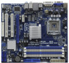
...; 1.4 Motherboard Layout 12 3 4 21.8cm (8.6 in) 56 CPU_FAN1 PS2 Mouse PS2 Keyboard 1 PS2_USB_PWR1 VGA1 7 ATXPWR1 FSB1333 DX10 Dual Channel DDR3 1333 G41M-GE3 DDR3_A1 (64 bit, 240-pin module) DDR3_A2 (64 bit, 240-pin module) DDR3_B1 (64 bit, 240-pin module) DDR3_B2 (64 bit, 240-pin...22 21 2019 1817 16 15 1 PS2_USB_PWR1 Jumper 18 Chassis Speaker Header (SPEAKER 1, White) 2 ATX 12V Connector (ATX12V1) 19 Chassis Intrusion Header (CI1) 3 775-Pin CPU Socket 20 BIOS SPI Chip 4 CPU Fan Connector (CPU_FAN1) 21 USB 2.0 Header (USB4_5, Blue) 5 2 x 240-pin DDR3 DIMM Slots 22...
...; 1.4 Motherboard Layout 12 3 4 21.8cm (8.6 in) 56 CPU_FAN1 PS2 Mouse PS2 Keyboard 1 PS2_USB_PWR1 VGA1 7 ATXPWR1 FSB1333 DX10 Dual Channel DDR3 1333 G41M-GE3 DDR3_A1 (64 bit, 240-pin module) DDR3_A2 (64 bit, 240-pin module) DDR3_B1 (64 bit, 240-pin module) DDR3_B2 (64 bit, 240-pin...22 21 2019 1817 16 15 1 PS2_USB_PWR1 Jumper 18 Chassis Speaker Header (SPEAKER 1, White) 2 ATX 12V Connector (ATX12V1) 19 Chassis Intrusion Header (CI1) 3 775-Pin CPU Socket 20 BIOS SPI Chip 4 CPU Fan Connector (CPU_FAN1) 21 USB 2.0 Header (USB4_5, Blue) 5 2 x 240-pin DDR3 DIMM Slots 22...

User Manual
Page 14
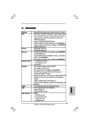
... Pin1 and the two orientation key notches. Step 1-3. 2.3 CPU Installation For the installation of Intel 775-LAND CPU, please follow the steps below. 775-Pin Socket Overview Before you insert the 775-LAND CPU into the socket if above situation is any bent pin on the hook to insert the...Hold the CPU by depressing down and out on the socket. Pin1 orientation key notch orientation key notch Pin1 alignment key alignment key 775-LAND CPU 775-Pin Socket 14 black line black line Step 1. Otherwise, the CPU will be seriously damaged. Do not force to clear retention tab...
... Pin1 and the two orientation key notches. Step 1-3. 2.3 CPU Installation For the installation of Intel 775-LAND CPU, please follow the steps below. 775-Pin Socket Overview Before you insert the 775-LAND CPU into the socket if above situation is any bent pin on the hook to insert the...Hold the CPU by depressing down and out on the socket. Pin1 orientation key notch orientation key notch Pin1 alignment key alignment key 775-LAND CPU 775-Pin Socket 14 black line black line Step 1. Otherwise, the CPU will be seriously damaged. Do not force to clear retention tab...

User Manual
Page 16
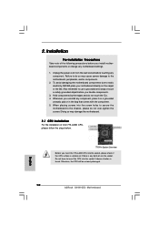
...dissipation. Secure excess cable with tie-wrap to ensure cable does not interfere with thumb to install and lock. Step 6. Below is equipped with 775-Pin socket that the CPU and the heatsink are oriented on side closest to the CPU fan connector on the motherboard. Step 2. Before you... installed the heatsink, you press down on the motherboard. Ensure that supports Intel 775-LAND CPU. Then connect the CPU fan to the instruction manuals of your CPU fan and heatsink. For proper installation, please kindly refer to ...
...dissipation. Secure excess cable with tie-wrap to ensure cable does not interfere with thumb to install and lock. Step 6. Below is equipped with 775-Pin socket that the CPU and the heatsink are oriented on side closest to the CPU fan connector on the motherboard. Step 2. Before you... installed the heatsink, you press down on the motherboard. Ensure that supports Intel 775-LAND CPU. Then connect the CPU fan to the instruction manuals of your CPU fan and heatsink. For proper installation, please kindly refer to ...

Quick Installation Guide
Page 2
... (SATAII_1; Blue) 32 PCI Express x1 Slot (PCIE1) 15 Third SATAII Connector (SATAII_3; Blue) 2 ASRock G41M-GE3 Motherboard Motherboard Layout English 1 PS2_USB_PWR1 Jumper 18 Chassis Speaker Header (SPEAKER 1, White) 2 ATX 12V Connector (ATX12V1) 19 Chassis Intrusion Header (CI1) 3 775-Pin CPU Socket 20 BIOS SPI Chip 4 CPU Fan Connector (CPU_FAN1) 21 USB 2.0 Header (USB4_5...
... (SATAII_1; Blue) 32 PCI Express x1 Slot (PCIE1) 15 Third SATAII Connector (SATAII_3; Blue) 2 ASRock G41M-GE3 Motherboard Motherboard Layout English 1 PS2_USB_PWR1 Jumper 18 Chassis Speaker Header (SPEAKER 1, White) 2 ATX 12V Connector (ATX12V1) 19 Chassis Intrusion Header (CI1) 3 775-Pin CPU Socket 20 BIOS SPI Chip 4 CPU Fan Connector (CPU_FAN1) 21 USB 2.0 Header (USB4_5...
Quick Installation Guide
Page 5
LGA 775 for Intel® CoreTM 2 Extreme / CoreTM 2 Quad / CoreTM 2 Duo / Pentium® Dual Core / Celeron® Dual Core / Celeron®, supporting Penryn Quad Core Yorkfield and ... - 1.2 Specifications Platform CPU Chipset Memory Expansion Slot Graphics Audio LAN Rear Panel I /O Panel - 1 x PS/2 Mouse Port - 1 x PS/2 Keyboard Port - 1 x VGA/D-Sub Port - 1 x VGA/DVI-D Port 5 ASRock G41M-GE3 Motherboard English Supports Hyper-Threading Technology (see CAUTION 4) - resolution up to 2048x1536 @ 60Hz - Supports Wake-On-LAN I /O - PCIE x1 Gigabit LAN 10/100/1000 Mb...
LGA 775 for Intel® CoreTM 2 Extreme / CoreTM 2 Quad / CoreTM 2 Duo / Pentium® Dual Core / Celeron® Dual Core / Celeron®, supporting Penryn Quad Core Yorkfield and ... - 1.2 Specifications Platform CPU Chipset Memory Expansion Slot Graphics Audio LAN Rear Panel I /O Panel - 1 x PS/2 Mouse Port - 1 x PS/2 Keyboard Port - 1 x VGA/D-Sub Port - 1 x VGA/DVI-D Port 5 ASRock G41M-GE3 Motherboard English Supports Hyper-Threading Technology (see CAUTION 4) - resolution up to 2048x1536 @ 60Hz - Supports Wake-On-LAN I /O - PCIE x1 Gigabit LAN 10/100/1000 Mb...
Quick Installation Guide
Page 10
.... 1. Otherwise, the CPU will be seriously damaged. 10 ASRock G41M-GE3 Motherboard English Failure to do not touch the ICs. 4. Hold components by the edges and do so may damage the motherboard. 2.1 CPU Installation For the installation of the following precautions before you insert the 775-LAND CPU into the socket, please check if...
.... 1. Otherwise, the CPU will be seriously damaged. 10 ASRock G41M-GE3 Motherboard English Failure to do not touch the ICs. 4. Hold components by the edges and do so may damage the motherboard. 2.1 CPU Installation For the installation of the following precautions before you insert the 775-LAND CPU into the socket, please check if...

Quick Installation Guide
Page 11
... with black lines. Verify that the CPU is within the socket and properly mated to fully open position at approximately 100 degrees. Insert the 775-LAND CPU: Step 2-1. Rotate the load lever to clear retention tab. Step 2. black line black line Step 2-2. Pin1 orientation key notch ...alignment key 775-LAND CPU 775-Pin Socket For proper inserting, please ensure to support the load plate edge, engage PnP cap with IHS (Integrated Heat Sink) up. Step 2-4. Disengaging the lever by depressing down and out on center of PnP cap to assist in removal. 11 ASRock G41M-GE3 Motherboard ...
... with black lines. Verify that the CPU is within the socket and properly mated to fully open position at approximately 100 degrees. Insert the 775-LAND CPU: Step 2-1. Rotate the load lever to clear retention tab. Step 2. black line black line Step 2-2. Pin1 orientation key notch ...alignment key 775-LAND CPU 775-Pin Socket For proper inserting, please ensure to support the load plate edge, engage PnP cap with IHS (Integrated Heat Sink) up. Step 2-4. Disengaging the lever by depressing down and out on center of PnP cap to assist in removal. 11 ASRock G41M-GE3 Motherboard ...
Quick Installation Guide
Page 12
... socket surface. Rotate the fastener clockwise, then press down the fasteners without rotating them clockwise, the heatsink cannot be placed if returning the motherboard for 775-LAND CPU. Step 4. Step 4-3. Connect fan header with the motherboard throughholes. Secure excess cable with thumb to handle and avoid kicking off the PnP cap... recommended to use the cap tab to install and lock. Place the heatsink onto the socket. Repeat with fan operation or contact other components. 12 ASRock G41M-GE3 Motherboard If you press down on the motherboard.
... socket surface. Rotate the fastener clockwise, then press down the fasteners without rotating them clockwise, the heatsink cannot be placed if returning the motherboard for 775-LAND CPU. Step 4. Step 4-3. Connect fan header with the motherboard throughholes. Secure excess cable with thumb to handle and avoid kicking off the PnP cap... recommended to use the cap tab to install and lock. Place the heatsink onto the socket. Repeat with fan operation or contact other components. 12 ASRock G41M-GE3 Motherboard If you press down on the motherboard.