
Quick Installation Guide
Page 4
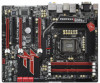
... I/O 64Mb BIOS SATA2_2_3 SATA2_4_5 USB3_4_5 IDE1 9 10 11 12 13 14 15 SATA3_A3_A4 SATA3_A1_A2 SATA3_0_1 36 PCIE4 16 35 FATAL1TY Designed in Taipei PCI2 1394a Front USB 3.0 Z 6 8 P HDMI_SPDIF1 ROFESSIONAL GEN3 ErP/EuP Ready HDMI 1.4a DX10.1 Dr. Debug PWRBTN RSTBTN 1 PCIE5 HD_AUDIO1 IR1 SATA3 6Gb/s FLOPPY1 COM1 USB6_7 ...2.0 x1 Slot (PCIE1, Black) 20 Power LED Header (PLED1) 42 Power Fan Connector (PWR_FAN1) 21 System Panel Header (PANEL1, Black) 43 1155-Pin CPU Socket 22 Chassis Fan Connector (CHA_FAN1) 4 Fatal1ty Z68 Professional Gen3 Series Motherboard English
... I/O 64Mb BIOS SATA2_2_3 SATA2_4_5 USB3_4_5 IDE1 9 10 11 12 13 14 15 SATA3_A3_A4 SATA3_A1_A2 SATA3_0_1 36 PCIE4 16 35 FATAL1TY Designed in Taipei PCI2 1394a Front USB 3.0 Z 6 8 P HDMI_SPDIF1 ROFESSIONAL GEN3 ErP/EuP Ready HDMI 1.4a DX10.1 Dr. Debug PWRBTN RSTBTN 1 PCIE5 HD_AUDIO1 IR1 SATA3 6Gb/s FLOPPY1 COM1 USB6_7 ...2.0 x1 Slot (PCIE1, Black) 20 Power LED Header (PLED1) 42 Power Fan Connector (PWR_FAN1) 21 System Panel Header (PANEL1, Black) 43 1155-Pin CPU Socket 22 Chassis Fan Connector (CHA_FAN1) 4 Fatal1ty Z68 Professional Gen3 Series Motherboard English

Quick Installation Guide
Page 14
... was a provision regulated by European Union to define the power consumption for more details. 14 Fatal1ty Z68 Professional Gen3 Series Motherboard English Please be noticed that not all the 775 and 1156 CPU Fan can be under 100 mA current ... again. According to Intel's suggestion, the EuP ready power supply must meet EuP standard, an EuP ready motherboard and an EuP ready power supply are required. According to EuP, the total AC power of 5v standby ... improve heat dissipation, remember to adopt three different CPU cooler types, Socket LGA 775, LGA 1155 and LGA 1156.
... was a provision regulated by European Union to define the power consumption for more details. 14 Fatal1ty Z68 Professional Gen3 Series Motherboard English Please be noticed that not all the 775 and 1156 CPU Fan can be under 100 mA current ... again. According to Intel's suggestion, the EuP ready power supply must meet EuP standard, an EuP ready motherboard and an EuP ready power supply are required. According to EuP, the total AC power of 5v standby ... improve heat dissipation, remember to adopt three different CPU cooler types, Socket LGA 775, LGA 1155 and LGA 1156.

Quick Installation Guide
Page 15
...bag that comes with the component. 5. Unplug the power cord from the wall socket before you insert the 1155-Pin CPU into the socket if above situation is any component. To avoid damaging the motherboard components due to the motherboard, peripherals, and/or components. 2. When placing screws into the screw holes to... by the edges and do not over-tighten the screws! Doing so may cause severe damage to static electricity, NEVER place your motherboard directly on the socket. Otherwise, the CPU will be seriously damaged. 15 Fatal1ty Z68 Professional Gen3 Series Motherboard English
...bag that comes with the component. 5. Unplug the power cord from the wall socket before you insert the 1155-Pin CPU into the socket if above situation is any component. To avoid damaging the motherboard components due to the motherboard, peripherals, and/or components. 2. When placing screws into the screw holes to... by the edges and do not over-tighten the screws! Doing so may cause severe damage to static electricity, NEVER place your motherboard directly on the socket. Otherwise, the CPU will be seriously damaged. 15 Fatal1ty Z68 Professional Gen3 Series Motherboard English

Quick Installation Guide
Page 16
... with black lines. Step 1-3. black line English 1. This cap must be placed if returning the motherboard for after service. Step 3. orientation key notch alignment key Pin1 Pin1 orientation key notch 1155-Pin CPU alignment key 1155-Pin Socket For proper inserting, please ensure to handle and avoid kicking off the PnP cap. 2. Insert the... fully open position at approximately 100 degrees. Step 2. It is recommended to use the cap tab to match the two orientation key notches of the socket. 16 Fatal1ty Z68 Professional Gen3 Series Motherboard Step 3-2.
... with black lines. Step 1-3. black line English 1. This cap must be placed if returning the motherboard for after service. Step 3. orientation key notch alignment key Pin1 Pin1 orientation key notch 1155-Pin CPU alignment key 1155-Pin Socket For proper inserting, please ensure to handle and avoid kicking off the PnP cap. 2. Insert the... fully open position at approximately 100 degrees. Step 2. It is recommended to use the cap tab to match the two orientation key notches of the socket. 16 Fatal1ty Z68 Professional Gen3 Series Motherboard Step 3-2.

Quick Installation Guide
Page 17
...Ensure fan cables are for 1155-Pin CPU. Repeat with the motherboard throughholes. Below is within the socket and properly mated to the orient keys. Step 2. Connect fan header with the CPU fan connector on the motherboard (CPU_ FAN1, see page ...Socket LGA 775, LGA 1155 and LGA 1156. If you press down on the motherboard. English Step 5. The white throughholes are oriented on side closest to ensure cable does not interfere with thumb to the instruction manuals of the heatsink for Socket LGA 1155/1156 CPU fan. 17 Fatal1ty Z68 Professional Gen3 Series Motherboard...
...Ensure fan cables are for 1155-Pin CPU. Repeat with the motherboard throughholes. Below is within the socket and properly mated to the orient keys. Step 2. Connect fan header with the CPU fan connector on the motherboard (CPU_ FAN1, see page ...Socket LGA 775, LGA 1155 and LGA 1156. If you press down on the motherboard. English Step 5. The white throughholes are oriented on side closest to ensure cable does not interfere with thumb to the instruction manuals of the heatsink for Socket LGA 1155/1156 CPU fan. 17 Fatal1ty Z68 Professional Gen3 Series Motherboard...

Quick Installation Guide
Page 251
4 4-1 HIS 4-2 4-3 2.2 CPU CPU 以下は、1155-LAND CPU 1 HIS 2 CPU_FAN1、4 No. 3 CPU 3 4 5 CPU 6 C.C.O Socket LGA 775、LGA 1155 と LGA 1156 の 3 CPU Socket LGA 1155/1156 CPU 251 Fatal1ty Z68 Professional Gen3 Series Motherboard 日本語
4 4-1 HIS 4-2 4-3 2.2 CPU CPU 以下は、1155-LAND CPU 1 HIS 2 CPU_FAN1、4 No. 3 CPU 3 4 5 CPU 6 C.C.O Socket LGA 775、LGA 1155 と LGA 1156 の 3 CPU Socket LGA 1155/1156 CPU 251 Fatal1ty Z68 Professional Gen3 Series Motherboard 日本語


