
User Manual
Page 2
... or fitness for any errors or omissions that may apply, see www.dtsc.ca.gov/hazardouswaste/ perchlorate" ASRock Website: http://www.asrock.com When you discard the Lithium battery in California, USA, please follow the related regulations in Perchlorate Best...only for identification or explanation and to infringe. Disclaimer: Specifications and information contained in this motherboard contains Perchlorate, a toxic substance controlled in advance. ASRock assumes no event shall ASRock, its directors, officers, employees, or agents be constructed as a commitment by the California ...
... or fitness for any errors or omissions that may apply, see www.dtsc.ca.gov/hazardouswaste/ perchlorate" ASRock Website: http://www.asrock.com When you discard the Lithium battery in California, USA, please follow the related regulations in Perchlorate Best...only for identification or explanation and to infringe. Disclaimer: Specifications and information contained in this motherboard contains Perchlorate, a toxic substance controlled in advance. ASRock assumes no event shall ASRock, its directors, officers, employees, or agents be constructed as a commitment by the California ...

User Manual
Page 7
Contents Chapter 1 Introduction 1 1.1 Package Contents 1 1.2 Specifications 2 1.3 Motherboard Layout 7 1.4 I/O Panel 10 1.5 Intel® WiFi-802.11ac Module 8265 (AC Wave 2 + BLE BT4.2) and ASRock WiFi 2.4/5 GHz Antenna 12 Chapter 2 Installation 13 2.1 Installing the CPU 14 2.2 Installing the CPU Fan and Heatsink 17 2.3 Installing Memory ... Installation Guide 27 Chapter 3 Software and Utilities Operation 31 3.1 Installing Drivers 31 3.2 F-Stream 32 3.2.1 Installing F-Stream 32 3.2.2 Using F-Stream 32 3.3 ASRock Live Update & APP Shop 35 3.3.1 UI Overview 35
Contents Chapter 1 Introduction 1 1.1 Package Contents 1 1.2 Specifications 2 1.3 Motherboard Layout 7 1.4 I/O Panel 10 1.5 Intel® WiFi-802.11ac Module 8265 (AC Wave 2 + BLE BT4.2) and ASRock WiFi 2.4/5 GHz Antenna 12 Chapter 2 Installation 13 2.1 Installing the CPU 14 2.2 Installing the CPU Fan and Heatsink 17 2.3 Installing Memory ... Installation Guide 27 Chapter 3 Software and Utilities Operation 31 3.1 Installing Drivers 31 3.2 F-Stream 32 3.2.1 Installing F-Stream 32 3.2.2 Using F-Stream 32 3.3 ASRock Live Update & APP Shop 35 3.3.1 UI Overview 35

User Manual
Page 11
... list on ASRock's website without notice. ASRock website http://www.asrock.com. 1.1 Package Contents • ASRock Fatal1ty Z370 Gaming-ITX/ac Series Motherboard (Mini-ITX Form Factor) • ASRock Fatal1ty Z370 Gaming-ITX/ac Series Quick Installation Guide • ASRock Fatal1ty Z370 Gaming-ITX/ac Series Support CD • 2 x Serial ATA (SATA) Data Cables (Optional) • 1 x ASRock WiFi 2.4/5 GHz Antenna (Optional) • 1 x Screw for purchasing ASRock Fatal1ty Z370 Gaming-ITX/ac Series motherboard, a reliable motherboard produced under ASRock's consistently stringent...
... list on ASRock's website without notice. ASRock website http://www.asrock.com. 1.1 Package Contents • ASRock Fatal1ty Z370 Gaming-ITX/ac Series Motherboard (Mini-ITX Form Factor) • ASRock Fatal1ty Z370 Gaming-ITX/ac Series Quick Installation Guide • ASRock Fatal1ty Z370 Gaming-ITX/ac Series Support CD • 2 x Serial ATA (SATA) Data Cables (Optional) • 1 x ASRock WiFi 2.4/5 GHz Antenna (Optional) • 1 x Screw for purchasing ASRock Fatal1ty Z370 Gaming-ITX/ac Series motherboard, a reliable motherboard produced under ASRock's consistently stringent...

User Manual
Page 17
PS2 Keyboard /Mouse USB 3.1 Gen1 T: USB1 B: USB2 1.3 Motherboard Layout Top Side View 1 2 CLR BTN1 CHA_FAN1 M2_2_WIFI RoHS ATX12V1 Fatal1ty Z370 Gaming-ITX/ac Series 3 4 5 CPU_FAN1 CPU_OPT/W_PUMP RGB_LED1 6 1 Ultra M.2 PCIe Gen3 x4 AT X P W R 1 DDR4_B1 (64 bit, 288-pin module) USB3_5_6 DDR4_A1 (64 bit, 288-pin module) Optical SPDIF HDMI1 DP_1 Z370 Gaming-ITX/ac 7 USB 3.1 Gen1 T: USB3 B: USB4 TB_1 SATA3_5 Top...
PS2 Keyboard /Mouse USB 3.1 Gen1 T: USB1 B: USB2 1.3 Motherboard Layout Top Side View 1 2 CLR BTN1 CHA_FAN1 M2_2_WIFI RoHS ATX12V1 Fatal1ty Z370 Gaming-ITX/ac Series 3 4 5 CPU_FAN1 CPU_OPT/W_PUMP RGB_LED1 6 1 Ultra M.2 PCIe Gen3 x4 AT X P W R 1 DDR4_B1 (64 bit, 288-pin module) USB3_5_6 DDR4_A1 (64 bit, 288-pin module) Optical SPDIF HDMI1 DP_1 Z370 Gaming-ITX/ac 7 USB 3.1 Gen1 T: USB3 B: USB4 TB_1 SATA3_5 Top...

User Manual
Page 22
BT 4.2 also includes Low Energy Technology and ensures extraordinary low power consumption for WiFi 802.11 a/b/ g/n/ac connectivity standards and Bluetooth v4.2. ASRock WiFi 2.4/5 GHz Antenna 12 English WiFi + BT module is an easy-touse wireless local area network (WLAN) adapter to the ...vary according to support WiFi + BT. 1.5 Intel® WiFi-802.11ac Module 8265 (AC Wave 2 + BLE BT4.2) and ASRock WiFi 2.4/5 GHz Antenna WiFi-802.11ac + BT Module This motherboard comes with an exclusive WiFi 802.11 a/b/g/n/ac + BT v4.2 module (pre-installed on the rear I/O panel) that adds a whole...
BT 4.2 also includes Low Energy Technology and ensures extraordinary low power consumption for WiFi 802.11 a/b/ g/n/ac connectivity standards and Bluetooth v4.2. ASRock WiFi 2.4/5 GHz Antenna 12 English WiFi + BT module is an easy-touse wireless local area network (WLAN) adapter to the ...vary according to support WiFi + BT. 1.5 Intel® WiFi-802.11ac Module 8265 (AC Wave 2 + BLE BT4.2) and ASRock WiFi 2.4/5 GHz Antenna WiFi-802.11ac + BT Module This motherboard comes with an exclusive WiFi 802.11 a/b/g/n/ac + BT v4.2 module (pre-installed on the rear I/O panel) that adds a whole...
User Manual
Page 23
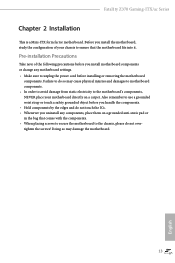
... do so may damage the motherboard. 13 English Fatal1ty Z370 Gaming-ITX/ac Series Chapter 2 Installation This is a Mini-ITX form factor motherboard. Also remember to unplug the power cord before you handle the components. • Hold components by the edges and do not overtighten the screws! Pre-installation Precautions Take note of your motherboard directly on a grounded anti...
... do so may damage the motherboard. 13 English Fatal1ty Z370 Gaming-ITX/ac Series Chapter 2 Installation This is a Mini-ITX form factor motherboard. Also remember to unplug the power cord before you handle the components. • Hold components by the edges and do not overtighten the screws! Pre-installation Precautions Take note of your motherboard directly on a grounded anti...

User Manual
Page 26
Please save and replace the cover if the processor is removed. The cover must be placed if you wish to return the motherboard for after service. 16 English
Please save and replace the cover if the processor is removed. The cover must be placed if you wish to return the motherboard for after service. 16 English

User Manual
Page 28
... cause permanent damage to install a DDR, DDR2 or DDR3 memory module into the slot at incorrect orientation. 18 English 2.3 Installing Memory Modules (DIMM) This motherboard provides two 288-pin DDR4 (Double Data Rate 4) DIMM slots, and supports Dual Channel Memory Technology. 1. For dual channel configuration, you force the DIMM... into a DDR4 slot; The DIMM only fits in one memory module installed. 3. It is not allowed to the motherboard and the DIMM if you always need to activate Dual Channel Memory Technology with only one correct orientation.
... cause permanent damage to install a DDR, DDR2 or DDR3 memory module into the slot at incorrect orientation. 18 English 2.3 Installing Memory Modules (DIMM) This motherboard provides two 288-pin DDR4 (Double Data Rate 4) DIMM slots, and supports Dual Channel Memory Technology. 1. For dual channel configuration, you force the DIMM... into a DDR4 slot; The DIMM only fits in one memory module installed. 3. It is not allowed to the motherboard and the DIMM if you always need to activate Dual Channel Memory Technology with only one correct orientation.

User Manual
Page 30
PCIe slot: PCIE1 (PCIe 3.0 x16 slot) is unplugged. Before installing an expansion card, please make necessary hardware settings for PCI Express x16 lane width graphics cards. 20 English 2.4 Expansion Slots (PCI Express Slot) There is 1 PCI Express slot slot on the motherboard. Please read the documentation of the expansion card and make sure that the power supply is switched off or the power cord is used for the card before you start the installation.
PCIe slot: PCIE1 (PCIe 3.0 x16 slot) is unplugged. Before installing an expansion card, please make necessary hardware settings for PCI Express x16 lane width graphics cards. 20 English 2.4 Expansion Slots (PCI Express Slot) There is 1 PCI Express slot slot on the motherboard. Please read the documentation of the expansion card and make sure that the power supply is switched off or the power cord is used for the card before you start the installation.
User Manual
Page 31
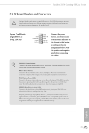
...pin assignments are NOT jumpers. Placing jumper caps over these headers and connectors. English 21 RESET (Reset Button): Connect to the motherboard. The LED is off when the system is reading or writing data. Do NOT place jumper caps over the headers and ... chassis front panel. The LED is on the chassis to turn off (S5). PLED (System Power LED): Connect to perform a normal restart. Fatal1ty Z370 Gaming-ITX/ac Series 2.5 Onboard Headers and Connectors Onboard headers and connectors are matched correctly. System Panel Header (9-pin PANEL1) (see p.7, No. 12) GND ...
...pin assignments are NOT jumpers. Placing jumper caps over these headers and connectors. English 21 RESET (Reset Button): Connect to the motherboard. The LED is off when the system is reading or writing data. Do NOT place jumper caps over the headers and ... chassis front panel. The LED is on the chassis to turn off (S5). PLED (System Power LED): Connect to perform a normal restart. Fatal1ty Z370 Gaming-ITX/ac Series 2.5 Onboard Headers and Connectors Onboard headers and connectors are matched correctly. System Panel Header (9-pin PANEL1) (see p.7, No. 12) GND ...

User Manual
Page 32
... internal storage devices with up to 6.0 Gb/s data transfer rate. Each USB 2.0 header can support two ports. English 22 There is one header on this motherboard. Serial ATA3 Connectors (SATA3_0: see p.7, No. 17) (SATA3_1: see p.7, No. 16) SATA3_3 SATA3_2 (SATA3_2: SATA3_0 SATA3_1 see p.7, No. 15) (SATA3_3: see p.7, No. 18)...pin USB1_2) (see p.7, No. 10) Vbus IntA_PA_SSRXIntA_PA_SSRX+ GND IntA_PA_SSTXIntA_PA_SSTX+ GND IntA_PA_DIntA_PA_D+ Vbus IntA_PB_SSRXIntA_PB_SSRX+ GND IntA_PB_SSTXIntA_PB_SSTX+ GND IntA_PB_DIntA_PB_D+ Dummy 1 There is one header on this motherboard.
... internal storage devices with up to 6.0 Gb/s data transfer rate. Each USB 2.0 header can support two ports. English 22 There is one header on this motherboard. Serial ATA3 Connectors (SATA3_0: see p.7, No. 17) (SATA3_1: see p.7, No. 16) SATA3_3 SATA3_2 (SATA3_2: SATA3_0 SATA3_1 see p.7, No. 15) (SATA3_3: see p.7, No. 18)...pin USB1_2) (see p.7, No. 10) Vbus IntA_PA_SSRXIntA_PA_SSRX+ GND IntA_PA_SSTXIntA_PA_SSTX+ GND IntA_PA_DIntA_PA_D+ Vbus IntA_PB_SSRXIntA_PB_SSRX+ GND IntA_PB_SSTXIntA_PB_SSTX+ GND IntA_PB_DIntA_PB_D+ Dummy 1 There is one header on this motherboard.
User Manual
Page 33
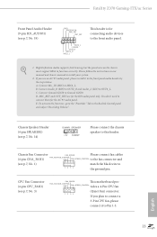
Fatal1ty Z370 Gaming-ITX/ac Series Front Panel Audio Header (9-pin HD_AUDIO1) (see p.7, No. 1) match the...MIC) to the "FrontMic" Tab in our manual and chassis manual to this header. If you use an AC'97 audio panel, please install it to the front panel audio header by the steps below: A. FAN_VOLTAGE_CONTROL FAN_SPEED_CONTROL ...panel and adjust "Recording Volume". B. D. Chassis Speaker Header (4-pin SPEAKER1) (see p.7, No. 3) FAN_SPEED This motherboard pro- CPU Fan Connector (4-pin CPU_FAN1) (see p.7, No. 14) DUMMY SPEAKER 1 +5V DUMMY Please connect the chassis speaker ...
Fatal1ty Z370 Gaming-ITX/ac Series Front Panel Audio Header (9-pin HD_AUDIO1) (see p.7, No. 1) match the...MIC) to the "FrontMic" Tab in our manual and chassis manual to this header. If you use an AC'97 audio panel, please install it to the front panel audio header by the steps below: A. FAN_VOLTAGE_CONTROL FAN_SPEED_CONTROL ...panel and adjust "Recording Volume". B. D. Chassis Speaker Header (4-pin SPEAKER1) (see p.7, No. 3) FAN_SPEED This motherboard pro- CPU Fan Connector (4-pin CPU_FAN1) (see p.7, No. 14) DUMMY SPEAKER 1 +5V DUMMY Please connect the chassis speaker ...

User Manual
Page 34
... 13. English 24 CPU Optional/Water Pump Fan Connector (4-pin CPU_OPT/W_ PUMP) (see p.7, No. 11) GND Signal This motherboard 1 supports CASE OPEN detection feature that detects if the chassis cove has been removed. Chassis Intrusion Header (2-pin CI1) (see p.7, No.... 4) FAN_SPEED This motherboard FAN_VOLTAGE_CONTROL GND FAN_SPEED_CONTROL provides a 4-Pin water cooling CPU fan connector. vides a 8-pin ATX 12V 4 1 power connector. To use a...
... 13. English 24 CPU Optional/Water Pump Fan Connector (4-pin CPU_OPT/W_ PUMP) (see p.7, No. 11) GND Signal This motherboard 1 supports CASE OPEN detection feature that detects if the chassis cove has been removed. Chassis Intrusion Header (2-pin CI1) (see p.7, No.... 4) FAN_SPEED This motherboard FAN_VOLTAGE_CONTROL GND FAN_SPEED_CONTROL provides a 4-Pin water cooling CPU fan connector. vides a 8-pin ATX 12V 4 1 power connector. To use a...

User Manual
Page 36
This function is workable only when you power off your computer and unplug the power supply. 2.6 Smart Button The motherboard has one smart buttone: Clear CMOS Button, allowing users to quickly clear the CMOS values. English 26 Clear CMOS Button (CLRCBTN) (see p.10, No. 18) Clear CMOS Button allows users to clear the CMOS values.
This function is workable only when you power off your computer and unplug the power supply. 2.6 Smart Button The motherboard has one smart buttone: Clear CMOS Button, allowing users to quickly clear the CMOS values. English 26 Clear CMOS Button (CLRCBTN) (see p.10, No. 18) Clear CMOS Button allows users to clear the CMOS values.
User Manual
Page 37
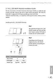
... M.2_SSD (NGFF) module, find the corresponding nut 2 location to replace mPCIe and mSATA. Installing the M.2_SSD (NGFF) Module Step 1 This motherboard supports M.2_SSD (NGFF) module type 2260 and 2280 only. Fatal1ty Z370 Gaming-ITX/ac Series 2.7 M.2_SSD (NGFF) Module Installation Guide The M.2, also known as the Next Generation Form Factor (NGFF), is a small size and versatile...
... M.2_SSD (NGFF) module, find the corresponding nut 2 location to replace mPCIe and mSATA. Installing the M.2_SSD (NGFF) Module Step 1 This motherboard supports M.2_SSD (NGFF) module type 2260 and 2280 only. Fatal1ty Z370 Gaming-ITX/ac Series 2.7 M.2_SSD (NGFF) Module Installation Guide The M.2, also known as the Next Generation Form Factor (NGFF), is a small size and versatile...

User Manual
Page 38
... gently insert the M.2 (NGFF) SSD module into place. Step 6 Tighten the screw with a screwdriver to Step 4. Step 4 Peel off the yellow protective film on the motherboard. Please be aware that the M.2 (NGFF) SSD module only fits in one orientation. Please do not overtighten the screw as this might damage the module...
... gently insert the M.2 (NGFF) SSD module into place. Step 6 Tighten the screw with a screwdriver to Step 4. Step 4 Peel off the yellow protective film on the motherboard. Please be aware that the M.2 (NGFF) SSD module only fits in one orientation. Please do not overtighten the screw as this might damage the module...
User Manual
Page 41
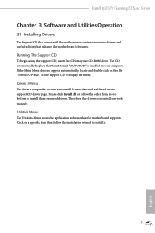
... item then follow the order from top to bottom to install it. 31 English Fatal1ty Z370 Gaming-ITX/ac Series Chapter 3 Software and Utilities Operation 3.1 Installing Drivers The Support CD that comes with the motherboard contains necessary drivers and useful utilities that the motherboard supports. Running The Support CD To begin using the support CD, insert the...
... item then follow the order from top to bottom to install it. 31 English Fatal1ty Z370 Gaming-ITX/ac Series Chapter 3 Software and Utilities Operation 3.1 Installing Drivers The Support CD that comes with the motherboard contains necessary drivers and useful utilities that the motherboard supports. Running The Support CD To begin using the support CD, insert the...
User Manual
Page 45
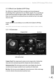
.... Hot News: The hot news section displays the various latest news. Double-click utility. Fatal1ty Z370 Gaming-ITX/ac Series 3.3 ASRock Live Update & APP Shop The ASRock Live Update & APP Shop is an online store for purchasing and downloading software applications for your motherboard up to visit the website of the selected news and know more. 35 English...
.... Hot News: The hot news section displays the various latest news. Double-click utility. Fatal1ty Z370 Gaming-ITX/ac Series 3.3 ASRock Live Update & APP Shop The ASRock Live Update & APP Shop is an online store for purchasing and downloading software applications for your motherboard up to visit the website of the selected news and know more. 35 English...

User Manual
Page 52
... x4 Z370 G aming-ITX/a c 1 1 1 B R 12V G 1. otherwise, the cable may cause damages to do not come with the package. 2. Please note that the RGB LED strips do so may be damaged. 2. The RGB LED header supports standard 5050 RGB LED strip (12V/G/R/B), with sophisticated tastes to the RGB LED Header (RGB_LED1) on the motherboard. 3.5 ASRock...
... x4 Z370 G aming-ITX/a c 1 1 1 B R 12V G 1. otherwise, the cable may cause damages to do not come with the package. 2. Please note that the RGB LED strips do so may be damaged. 2. The RGB LED header supports standard 5050 RGB LED strip (12V/G/R/B), with sophisticated tastes to the RGB LED Header (RGB_LED1) on the motherboard. 3.5 ASRock...
User Manual
Page 53
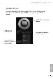
Drag the tab to customize your way! English 43 Download this utility from the drop-down menu. Fatal1ty Z370 Gaming-ITX/ac Series ASRock RGB LED Utility Now you can adjust the RGB LED color through the ASRock RGB LED utility. Toggle on/off the RGB LED switch Sync RGB LED effects for all LED regions of the motherboard Select a RGB LED light effect from the ASRock Live Update & APP Shop and start coloring your PC style your preference.
Drag the tab to customize your way! English 43 Download this utility from the drop-down menu. Fatal1ty Z370 Gaming-ITX/ac Series ASRock RGB LED Utility Now you can adjust the RGB LED color through the ASRock RGB LED utility. Toggle on/off the RGB LED switch Sync RGB LED effects for all LED regions of the motherboard Select a RGB LED light effect from the ASRock Live Update & APP Shop and start coloring your PC style your preference.

