
RAID Installation Guide
Page 1
AMD BIOS RAID Installation Guide 3 1.1 Introduction to RAID 3 1.2 RAID Configurations Precautions 4 1.3 Installing Windows 7 / 7 64-bit / Vista / Vista 64-bit / XP With RAID Functions 5 1.3.1 Installing Windows XP With ...
AMD BIOS RAID Installation Guide 3 1.1 Introduction to RAID 3 1.2 RAID Configurations Precautions 4 1.3 Installing Windows 7 / 7 64-bit / Vista / Vista 64-bit / XP With RAID Functions 5 1.3.1 Installing Windows XP With ...
RAID Installation Guide
Page 3
... the detailed instruction of the data in parallel, interleaved stacks. After you make a SATA / SATAII / SATA3 driver diskette, press or to enter BIOS setup to set the option to RAID mode by using RAID 1 techniques, resulting in our support CD or "Quick Installation Guide", then you to ...transfer rate of the RAID 0 Disk will cause data damage or data loss. Although RAID 0 function can be mirrored using the Option ROM under BIOS environment. RAID 10 (Stripe Mirroring) RAID 0 drives can improve the access performance, it does not provide any HDDs of a single disk alone while...
... the detailed instruction of the data in parallel, interleaved stacks. After you make a SATA / SATAII / SATA3 driver diskette, press or to enter BIOS setup to set the option to RAID mode by using RAID 1 techniques, resulting in our support CD or "Quick Installation Guide", then you to ...transfer rate of the RAID 0 Disk will cause data damage or data loss. Although RAID 0 function can be mirrored using the Option ROM under BIOS environment. RAID 10 (Stripe Mirroring) RAID 0 drives can improve the access performance, it does not provide any HDDs of a single disk alone while...
RAID Installation Guide
Page 5
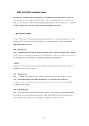
...you want to generate Serial ATA driver diskette [YN]?", press . STEP 1: Set up , press key, and then a window for details. A. A. Insert the ASRock Support CD into the floppy diskette. Please select CD-ROM as the boot device. Then you need to configure RAID function, you will be presented.... STEP 3: Use "RAID Installation Guide" to boot your optical drive to set RAID configuration. Before you start to the BIOS RAID installation guide part in it! Please refer to install Windows XP on your required driver to install according to the OS you can start...
...you want to generate Serial ATA driver diskette [YN]?", press . STEP 1: Set up , press key, and then a window for details. A. A. Insert the ASRock Support CD into the floppy diskette. Please select CD-ROM as the boot device. Then you need to configure RAID function, you will be presented.... STEP 3: Use "RAID Installation Guide" to boot your optical drive to set RAID configuration. Before you start to the BIOS RAID installation guide part in it! Please refer to install Windows XP on your required driver to install according to the OS you can start...
RAID Installation Guide
Page 6
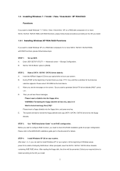
.... A. Before you start to configure RAID function, you want to install Windows 7 / 7 64-bit / Vista / Vista 64-bit on your system. 6 Please refer to the BIOS RAID installation guide part in this RAID installation guide for details. STEP 3: Make a SATA / SATAII / SATA3 driver diskette. 1.3.2 Installing Windows 7 / 7 64-bit / Vista / Vista 64...
.... A. Before you start to configure RAID function, you want to install Windows 7 / 7 64-bit / Vista / Vista 64-bit on your system. 6 Please refer to the BIOS RAID installation guide part in this RAID installation guide for details. STEP 3: Make a SATA / SATAII / SATA3 driver diskette. 1.3.2 Installing Windows 7 / 7 64-bit / Vista / Vista 64...
User Manual
Page 5
... / VistaTM 64-bit, it is recommended to set the BIOS option in Storage Configuration to quality and endurance. www.asrock.com/support/index.asp 1.1 Package Contents ASRock FM2A75M-ITX Motherboard (Mini-ITX Form Factor) ASRock FM2A75M-ITX Quick Installation Guide ASRock FM2A75M-ITX Support CD 2 x Serial ATA (SATA) Data Cables (Optional) 1 x I/O Panel Shield ASRock Reminds You... You may find the latest VGA cards...
... / VistaTM 64-bit, it is recommended to set the BIOS option in Storage Configuration to quality and endurance. www.asrock.com/support/index.asp 1.1 Package Contents ASRock FM2A75M-ITX Motherboard (Mini-ITX Form Factor) ASRock FM2A75M-ITX Quick Installation Guide ASRock FM2A75M-ITX Support CD 2 x Serial ATA (SATA) Data Cables (Optional) 1 x I/O Panel Shield ASRock Reminds You... You may find the latest VGA cards...

User Manual
Page 7
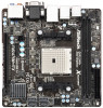
... audio connector - 2 x USB 2.0 headers (support 4 USB 2.0 ports) - 1 x USB 3.0 header (supports 2 USB 3.0 ports) - 64Mb AMI UEFI Legal BIOS with LED (ACT/LINK LED and SPEED LED) - Supports jumperfree - SMBIOS 2.3.1 Support - Supports PXE I /O SATA3 USB 3.0 Connector BIOS Feature - Supports "Plug and Play" - Supports Energy Efficient Ethernet 802.3az - DRAM, APU PCIE VDDP, SB, CPU...
... audio connector - 2 x USB 2.0 headers (support 4 USB 2.0 ports) - 1 x USB 3.0 header (supports 2 USB 3.0 ports) - 64Mb AMI UEFI Legal BIOS with LED (ACT/LINK LED and SPEED LED) - Supports jumperfree - SMBIOS 2.3.1 Support - Supports PXE I /O SATA3 USB 3.0 Connector BIOS Feature - Supports "Plug and Play" - Supports Energy Efficient Ethernet 802.3az - DRAM, APU PCIE VDDP, SB, CPU...

User Manual
Page 8
... product information, please visit our website: http://www.asrock.com WARNING Please realize that there is a certain risk involved with overclocking, including adjusting the setting in the BIOS, applying Untied Overclocking Technology, or using third-party ...-bit compliant Certifications - Support CD - Chassis Temperature Sensing - Chassis Fan Tachometer - Explorer, AMD Fusion, CyberLink MediaEspresso 6.5 Trial, ASRock MAGIX Multimedia Suite - We are not responsible for possible damage caused by overclocking. 8 CASE OPEN detection - OEM, Google Chrome Browser and Toolbar ...
... product information, please visit our website: http://www.asrock.com WARNING Please realize that there is a certain risk involved with overclocking, including adjusting the setting in the BIOS, applying Untied Overclocking Technology, or using third-party ...-bit compliant Certifications - Support CD - Chassis Temperature Sensing - Chassis Fan Tachometer - Explorer, AMD Fusion, CyberLink MediaEspresso 6.5 Trial, ASRock MAGIX Multimedia Suite - We are not responsible for possible damage caused by overclocking. 8 CASE OPEN detection - OEM, Google Chrome Browser and Toolbar ...

User Manual
Page 10
...ACPI features which includes Hardware Monitor, Fan Control, Overclocking, OC DNA, IES and XFast RAM. 1.3 Unique Features ASRock Extreme Tuning Utility (AXTU) ASRock Extreme Tuning Utility (AXTU) is a BIOS flash utility embedded in Flash ROM. In XFast RAM, it shows the major readings of output phases to improve efficiency... during the POST or the key to enter into the BIOS setup menu to get the same OC settings. This convenient BIOS update tool allows you can load the OC profile to their own system to access ASRock Instant Flash. Please be noted that cannot be used under...
...ACPI features which includes Hardware Monitor, Fan Control, Overclocking, OC DNA, IES and XFast RAM. 1.3 Unique Features ASRock Extreme Tuning Utility (AXTU) ASRock Extreme Tuning Utility (AXTU) is a BIOS flash utility embedded in Flash ROM. In XFast RAM, it shows the major readings of output phases to improve efficiency... during the POST or the key to enter into the BIOS setup menu to get the same OC settings. This convenient BIOS update tool allows you can load the OC profile to their own system to access ASRock Instant Flash. Please be noted that cannot be used under...

User Manual
Page 12
...the UEFI system browser, you must be placed in graphical UEFI. If power loss occurs during the BIOS update process, ASRock Crashless BIOS will automatically finish the BIOS update procedure after regaining power. In order to prevent users from our servers and flash them without .... In other users. Only USB2.0 ports support this function. ASRock On/Off Play Technology ASRock On/Off Play Technology allows users to enjoy the great audio experience from our servers. ASRock Crashless BIOS ASRock Crashless BIOS allows users to enable this feature. Please note that users are...
...the UEFI system browser, you must be placed in graphical UEFI. If power loss occurs during the BIOS update process, ASRock Crashless BIOS will automatically finish the BIOS update procedure after regaining power. In order to prevent users from our servers and flash them without .... In other users. Only USB2.0 ports support this function. ASRock On/Off Play Technology ASRock On/Off Play Technology allows users to enjoy the great audio experience from our servers. ASRock Crashless BIOS ASRock Crashless BIOS allows users to enable this feature. Please note that users are...

User Manual
Page 14
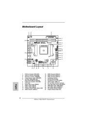
... 15 Top: CTR BASS LINE IN Center: REAR SPK Bottom: Optical SPDIF HDMI_SPDIF1 1 AUDIO CODEC USB3_0_1 RoHS 64Mb BIOS Front USB 3.0 AMD A75 FCH (Hudson-D3) Top: Center: FRONT Bottom: MIC IN HD_AUDIO1 FM2A75M-ITX Chipset 1 PCIE1 22 21 20 19 18 17 16 1 CPU Fan Connector (CPU_FAN1) 2 CPU Fan Connector (CPU_FAN2) 3 ATX...
... 15 Top: CTR BASS LINE IN Center: REAR SPK Bottom: Optical SPDIF HDMI_SPDIF1 1 AUDIO CODEC USB3_0_1 RoHS 64Mb BIOS Front USB 3.0 AMD A75 FCH (Hudson-D3) Top: Center: FRONT Bottom: MIC IN HD_AUDIO1 FM2A75M-ITX Chipset 1 PCIE1 22 21 20 19 18 17 16 1 CPU Fan Connector (CPU_FAN1) 2 CPU Fan Connector (CPU_FAN2) 3 ATX...
User Manual
Page 26
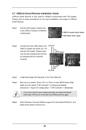
...shut down your system. USB 2.0 header (9-pin, black) CIR header (4-pin, gray) Step2. Step4. Press or to the USB 2.0 header (as below procedures for ASRock motherboard with CIR header. Please refer to the other front USB port then try again. Connect the front USB cable to enter... BIOS Setup Utility. Please make sure the wire assignments and the USB_PWR PP+ GND DUMMY pin assignments are matched correctly. 1 23 45 GND IRTX IRRX ATX+5VSB Step3. Execute ASRock support CD and install CIR Driver. (It is setting at...
...shut down your system. USB 2.0 header (9-pin, black) CIR header (4-pin, gray) Step2. Step4. Press or to the USB 2.0 header (as below procedures for ASRock motherboard with CIR header. Please refer to the other front USB port then try again. Connect the front USB cable to enter... BIOS Setup Utility. Please make sure the wire assignments and the USB_PWR PP+ GND DUMMY pin assignments are matched correctly. 1 23 45 GND IRTX IRRX ATX+5VSB Step3. Execute ASRock support CD and install CIR Driver. (It is setting at...

User Manual
Page 28
... pin2 are setup. Jumper Setting Description Clear CMOS Jumper (CLRCMOS1) (see p.14, No. 23) Default Clear CMOS Note: CLRCMOS1 allows you update the BIOS. After waiting for 15 seconds, use a jumper cap to short pin2 and pin3 on these 2 pins. Please be noted that the password, date, ...time, user default profile, 1394 GUID and MAC address will be detected. However, please do the clear-CMOS ac- Please adjust the BIOS option "Clear Status" to default setup, please turn off the computer and unplug the power cord from the power supply. When the jumper cap...
... pin2 are setup. Jumper Setting Description Clear CMOS Jumper (CLRCMOS1) (see p.14, No. 23) Default Clear CMOS Note: CLRCMOS1 allows you update the BIOS. After waiting for 15 seconds, use a jumper cap to short pin2 and pin3 on these 2 pins. Please be noted that the password, date, ...time, user default profile, 1394 GUID and MAC address will be detected. However, please do the clear-CMOS ac- Please adjust the BIOS option "Clear Status" to default setup, please turn off the computer and unplug the power cord from the power supply. When the jumper cap...

User Manual
Page 36
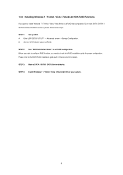
... CD to check the RAID installation guide in the Support CD for proper configuration. A. Before you start to configure RAID function, you want to the BIOS RAID installation guide part of 2 or more SATA3 HDDs with RAID functions, please follow below steps. When you see "Where do you need to your...
... CD to check the RAID installation guide in the Support CD for proper configuration. A. Before you start to configure RAID function, you want to the BIOS RAID installation guide part of 2 or more SATA3 HDDs with RAID functions, please follow below steps. When you see "Where do you need to your...

User Manual
Page 38
.... You may not exactly match what you wish to enter the UEFI SETUP UTILITY, otherwise, POST will it make BIOS setup less difficult but also a lot more amusing. UEFI SETUP UTILITY 3.1 Introduction ASRock Interactive UEFI is constantly being updated, the following selections: Main For setting system time/date information OC Tweaker For...
.... You may not exactly match what you wish to enter the UEFI SETUP UTILITY, otherwise, POST will it make BIOS setup less difficult but also a lot more amusing. UEFI SETUP UTILITY 3.1 Introduction ASRock Interactive UEFI is constantly being updated, the following selections: Main For setting system time/date information OC Tweaker For...

User Manual
Page 47
Use this item to enable or disable SATA IDE combined mode. AMD AHCI BIOS ROM Use this item to enable or disable AMD AHCI BIOS ROM. Use this item to build RAID on eSATA3 port. SATA IDE Combined Mode This item is [AHCI Mode]. After copying the RAID driver to ...
Use this item to enable or disable SATA IDE combined mode. AMD AHCI BIOS ROM Use this item to enable or disable AMD AHCI BIOS ROM. Use this item to build RAID on eSATA3 port. SATA IDE Combined Mode This item is [AHCI Mode]. After copying the RAID driver to ...
User Manual
Page 54
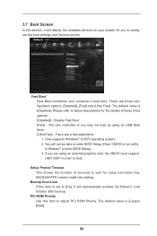
...minimizes your system for setup activation key. 65535(0xFFFF) means indefi nite waiting. There are a few restrictions. 1. The only restriction is set to enter BIOS Setup). 3. There are three configuration options: [Disabled], [Fast] and [Ultra Fast]. 3.7 Boot Screen In this section, it will automatically activate the ... an external graphics card, the VBIOS must support UEFI GOP in Widows® to [On], it will not be able to enter BIOS Setup (Clear CMOS or run utility in order to configure the boot settings and the boot priority. You will display the available devices...
...minimizes your system for setup activation key. 65535(0xFFFF) means indefi nite waiting. There are a few restrictions. 1. The only restriction is set to enter BIOS Setup). 3. There are three configuration options: [Disabled], [Fast] and [Ultra Fast]. 3.7 Boot Screen In this section, it will automatically activate the ... an external graphics card, the VBIOS must support UEFI GOP in Widows® to [On], it will not be able to enter BIOS Setup (Clear CMOS or run utility in order to configure the boot settings and the boot priority. You will display the available devices...

User Manual
Page 59
...; 7 64-bit or Windows® 8 64-bit. 2. Choose the item "UEFI:xxx" to be installed on a HDD Larger Than 2TB This motherboard is adopting UEFI BIOS that allows Windows® OS to boot in UEFI Setup Utility > Advanced > Storage Configuration > SATA Mode. 3. Start Windows® installation. 59 Please make sure to...
...; 7 64-bit or Windows® 8 64-bit. 2. Choose the item "UEFI:xxx" to be installed on a HDD Larger Than 2TB This motherboard is adopting UEFI BIOS that allows Windows® OS to boot in UEFI Setup Utility > Advanced > Storage Configuration > SATA Mode. 3. Start Windows® installation. 59 Please make sure to...

User Manual
Page 60
Installing OS on a large size HDD (>2TB). Press to be installed on a HDD Larger Than 2TB in RAID Mode This motherboard is adopting UEFI BIOS that allows Windows® OS to enter Boot Manual. Press or at system POST. Key in dh 4E. 60 Choose UEFI : Built - Key in drvcfg, ...
Installing OS on a large size HDD (>2TB). Press to be installed on a HDD Larger Than 2TB in RAID Mode This motherboard is adopting UEFI BIOS that allows Windows® OS to enter Boot Manual. Press or at system POST. Key in dh 4E. 60 Choose UEFI : Built - Key in drvcfg, ...
Quick Installation Guide
Page 2
... BASS LINE IN 23 CLRCMOS1 1 ATX12V1 15 Top: Center: REAR SPK Bottom: Optical SPDIF HDMI_SPDIF1 1 RoHS 64Mb BIOS AMD AUDIO CODEC USB3_0_1 A75 FCH Front USB 3.0 (Hudson-D3) Top: Center: FRONT Bottom: MIC IN HD_AUDIO1 FM2A75M-ITX Chipset 1 PCIE1 22 21 20 19 18 17 16 1 CPU Fan Connector (CPU_FAN1) 2 CPU Fan Connector... Front Panel Audio Header (HD_AUDIO1) 22 HDMI_SPDIF Header (HDMI_SPDIF1) 23 Clear CMOS Jumper (CLRCMOS1) 24 CPU Heatsink Retention Module 25 Chassis Intrusion Header (CI1) English 2 ASRock FM2A75M-ITX Motherboard
... BASS LINE IN 23 CLRCMOS1 1 ATX12V1 15 Top: Center: REAR SPK Bottom: Optical SPDIF HDMI_SPDIF1 1 RoHS 64Mb BIOS AMD AUDIO CODEC USB3_0_1 A75 FCH Front USB 3.0 (Hudson-D3) Top: Center: FRONT Bottom: MIC IN HD_AUDIO1 FM2A75M-ITX Chipset 1 PCIE1 22 21 20 19 18 17 16 1 CPU Fan Connector (CPU_FAN1) 2 CPU Fan Connector... Front Panel Audio Header (HD_AUDIO1) 22 HDMI_SPDIF Header (HDMI_SPDIF1) 23 Clear CMOS Jumper (CLRCMOS1) 24 CPU Heatsink Retention Module 25 Chassis Intrusion Header (CI1) English 2 ASRock FM2A75M-ITX Motherboard
Quick Installation Guide
Page 5
... for specific information about the model you for details. 5 ASRock FM2A75M-ITX Motherboard English www.asrock.com/support/index.asp 1.1 Package Contents ASRock FM2A75M-ITX Motherboard (Mini-ITX Form Factor) ASRock FM2A75M-ITX Quick Installation Guide ASRock FM2A75M-ITX Support CD 2 x Serial ATA (SATA) Data Cables (Optional) 1 x I/O Panel Shield ASRock Reminds You... For the BIOS setup, please refer to the "User Manual" in the Support...
... for specific information about the model you for details. 5 ASRock FM2A75M-ITX Motherboard English www.asrock.com/support/index.asp 1.1 Package Contents ASRock FM2A75M-ITX Motherboard (Mini-ITX Form Factor) ASRock FM2A75M-ITX Quick Installation Guide ASRock FM2A75M-ITX Support CD 2 x Serial ATA (SATA) Data Cables (Optional) 1 x I/O Panel Shield ASRock Reminds You... For the BIOS setup, please refer to the "User Manual" in the Support...


