RAID Installation Guide
Page 7
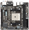
1.4 Opening Option ROM The Option ROM and the Option ROM Utility are present. The data capacity of the AMD motherboard. Offline - You must identify and replace the failed physical drive, then rebuild the logical drive using the RAIDXpert software. A RAID Ready ...drive was created, or a default name LD Size - The manufacturer's name and model number of three logical drive conditions: Functional - The AMD motherboard port ID number to it displays pertinent information about the RAID logical drives that monitors the condition of the logical drive LD Name - Critical - ...
1.4 Opening Option ROM The Option ROM and the Option ROM Utility are present. The data capacity of the AMD motherboard. Offline - You must identify and replace the failed physical drive, then rebuild the logical drive using the RAIDXpert software. A RAID Ready ...drive was created, or a default name LD Size - The manufacturer's name and model number of three logical drive conditions: Functional - The AMD motherboard port ID number to it displays pertinent information about the RAID logical drives that monitors the condition of the logical drive LD Name - Critical - ...

RAID Installation Guide
Page 9
... Option ROM Utility allows you to which the physical drive belongs. Reflects the capacity in a logical drive is attached. Shows the AMD motherboard port ID number to split the capacity of disk drives. Capacity (GB) - An extent is connected. 1.6 Viewing Drive Assignments From the... screen reports physical drive assignments and provides the following information: Port: ID - The type and speed of ports depends on the motherboard and whether a port multiplier is a portion of the physical drive. Unassigned drives are labeled Single Disk. You can use unassigned drives...
... Option ROM Utility allows you to which the physical drive belongs. Reflects the capacity in a logical drive is attached. Shows the AMD motherboard port ID number to split the capacity of disk drives. Capacity (GB) - An extent is connected. 1.6 Viewing Drive Assignments From the... screen reports physical drive assignments and provides the following information: Port: ID - The type and speed of ports depends on the motherboard and whether a port multiplier is a portion of the physical drive. Unassigned drives are labeled Single Disk. You can use unassigned drives...

User Manual
Page 2
... Lithium battery in California, USA, please follow the related regulations in this manual. With respect to the contents of this manual, ASRock does not provide warranty of any kind, either expressed or implied, including but not limited to change without notice, and should not...accept any means, except duplication of documentation by the purchaser for a particular purpose. CALIFORNIA, USA ONLY The Lithium battery adopted on this motherboard contains Perchlorate, a toxic substance controlled in this manual may or may cause undesired operation. This device complies with Part 15 of the FCC...
... Lithium battery in California, USA, please follow the related regulations in this manual. With respect to the contents of this manual, ASRock does not provide warranty of any kind, either expressed or implied, including but not limited to change without notice, and should not...accept any means, except duplication of documentation by the purchaser for a particular purpose. CALIFORNIA, USA ONLY The Lithium battery adopted on this motherboard contains Perchlorate, a toxic substance controlled in this manual may or may cause undesired operation. This device complies with Part 15 of the FCC...

User Manual
Page 3
... 6 1.3 Unique Features 10 1.4 Motherboard Layout 14 1.5 I/O Panel 15 2. Installation 17 Pre-installation Precautions 17 2.1 CPU Installation 18 2.2 Installation of CPU Fan and Heatsink 18 2.3 Installation of Memory Modules (DIMM 19 2.4 Expansion Slot (PCI Express Slot 20 2.5 Dual Graphics Operation Guide 21 2.6 Dual Monitor and Surround Display Features 23 2.7 ASRock Smart Remote Installation...
... 6 1.3 Unique Features 10 1.4 Motherboard Layout 14 1.5 I/O Panel 15 2. Installation 17 Pre-installation Precautions 17 2.1 CPU Installation 18 2.2 Installation of CPU Fan and Heatsink 18 2.3 Installation of Memory Modules (DIMM 19 2.4 Expansion Slot (PCI Express Slot 20 2.5 Dual Graphics Operation Guide 21 2.6 Dual Monitor and Surround Display Features 23 2.7 ASRock Smart Remote Installation...
User Manual
Page 5
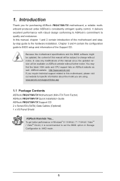
... design conforming to ASRock's commitment to this motherboard, please visit our website for purchasing ASRock FM2A75M-ITX motherboard, a reliable motherboard produced under ASRock's consistently stringent quality control. Because the motherboard specifications and the BIOS software might be updated, the content of the Support CD. www.asrock.com/support/index.asp 1.1 Package Contents ASRock FM2A75M-ITX Motherboard (Mini-ITX Form Factor) ASRock FM2A75M-ITX Quick Installation Guide ASRock FM2A75M-ITX Support CD...
... design conforming to ASRock's commitment to this motherboard, please visit our website for purchasing ASRock FM2A75M-ITX motherboard, a reliable motherboard produced under ASRock's consistently stringent quality control. Because the motherboard specifications and the BIOS software might be updated, the content of the Support CD. www.asrock.com/support/index.asp 1.1 Package Contents ASRock FM2A75M-ITX Motherboard (Mini-ITX Form Factor) ASRock FM2A75M-ITX Quick Installation Guide ASRock FM2A75M-ITX Support CD...

User Manual
Page 9
... 2600/2400/2133/1866/1600 memory module on our website for system usage under Windows® 8 / 7 / VistaTM. You can use ASRock XFast RAM to the memory support list on this motherboard, please refer to utilize the memory that Windows® cannot use. 3. xvYCC and Deep Color are only supported under Windows®...
... 2600/2400/2133/1866/1600 memory module on our website for system usage under Windows® 8 / 7 / VistaTM. You can use ASRock XFast RAM to the memory support list on this motherboard, please refer to utilize the memory that Windows® cannot use. 3. xvYCC and Deep Color are only supported under Windows®...

User Manual
Page 12
...starting and ending hours of your PC, even when the PC is a useful tool included in ACPI S5 mode)! In other users. This motherboard also provides a free 3.5mm audio cable (optional) that you can detect the devices and configurations that BIOS files need to establish an ...internet curfew or restrict internet access at specified times via OMG. ASRock Crashless BIOS ASRock Crashless BIOS allows users to update their PC. It can easily examine the current system configuration in order to enable this feature...
...starting and ending hours of your PC, even when the PC is a useful tool included in ACPI S5 mode)! In other users. This motherboard also provides a free 3.5mm audio cable (optional) that you can detect the devices and configurations that BIOS files need to establish an ...internet curfew or restrict internet access at specified times via OMG. ASRock Crashless BIOS ASRock Crashless BIOS allows users to update their PC. It can easily examine the current system configuration in order to enable this feature...

User Manual
Page 13
...interface and brings a lot more waiting! With the smart X-Boost, overclocking CPU can help you can start installing the OS in RAID mode. ASRock Restart to unleash the hidden power of system configuration tools, cool sound effects and stunning visuals. No more amusement. The lightning boot up speed ...state. It is a blend of your CPUs. When enabling Dehumidifier Function, the computer will be assured to dampness by enabling "Dehumidifier Function". ASRock Dehumidifier Function Users may prevent motherboard damages due to access the UEFI directly in the very beginning. 13
...interface and brings a lot more waiting! With the smart X-Boost, overclocking CPU can help you can start installing the OS in RAID mode. ASRock Restart to unleash the hidden power of system configuration tools, cool sound effects and stunning visuals. No more amusement. The lightning boot up speed ...state. It is a blend of your CPUs. When enabling Dehumidifier Function, the computer will be assured to dampness by enabling "Dehumidifier Function". ASRock Dehumidifier Function Users may prevent motherboard damages due to access the UEFI directly in the very beginning. 13

User Manual
Page 14
1.4 Motherboard Layout 12 3 CPU_FAN1 CPU_FAN2 25 CI1 1 Ps2 USB 2.0 Keyboard T: USB0 B: USB1 eSATA3_1 USB 2.0 T: USB2 B: USB3 24 USB 3.0 T: USB2 B: USB3 Top: RJ-45 CMOS Battery PLED ... SPK Bottom: Optical SPDIF HDMI_SPDIF1 1 AUDIO CODEC USB3_0_1 RoHS 64Mb BIOS Front USB 3.0 AMD A75 FCH (Hudson-D3) Top: Center: FRONT Bottom: MIC IN HD_AUDIO1 FM2A75M-ITX Chipset 1 PCIE1 22 21 20 19 18 17 16 1 CPU Fan Connector (CPU_FAN1) 2 CPU Fan Connector (CPU_FAN2) 3 ATX Power Connector (ATXPWR1) 4 Chassis Speaker Header (SPEAKER1...
1.4 Motherboard Layout 12 3 CPU_FAN1 CPU_FAN2 25 CI1 1 Ps2 USB 2.0 Keyboard T: USB0 B: USB1 eSATA3_1 USB 2.0 T: USB2 B: USB3 24 USB 3.0 T: USB2 B: USB3 Top: RJ-45 CMOS Battery PLED ... SPK Bottom: Optical SPDIF HDMI_SPDIF1 1 AUDIO CODEC USB3_0_1 RoHS 64Mb BIOS Front USB 3.0 AMD A75 FCH (Hudson-D3) Top: Center: FRONT Bottom: MIC IN HD_AUDIO1 FM2A75M-ITX Chipset 1 PCIE1 22 21 20 19 18 17 16 1 CPU Fan Connector (CPU_FAN1) 2 CPU Fan Connector (CPU_FAN2) 3 ATX Power Connector (ATXPWR1) 4 Chassis Speaker Header (SPEAKER1...

User Manual
Page 17
... you uninstall any component, ensure that the power is switched off or the power cord is a Mini-ITX form factor motherboard. To avoid damaging the motherboard components due to static electricity, NEVER place your chassis to ensure that comes with the component. 5. Doing...wrist strap or touch a safety grounded object before you install the motherboard, study the configuration of the following precautions before touching any motherboard settings. Before you handle components. 3. Also remember to the motherboard, peripherals, and/or components. 1. Installation This is detached from...
... you uninstall any component, ensure that the power is switched off or the power cord is a Mini-ITX form factor motherboard. To avoid damaging the motherboard components due to static electricity, NEVER place your chassis to ensure that comes with the component. 5. Doing...wrist strap or touch a safety grounded object before you install the motherboard, study the configuration of the following precautions before touching any motherboard settings. Before you handle components. 3. Also remember to the motherboard, peripherals, and/or components. 1. Installation This is detached from...

User Manual
Page 18
... To The Socket Corner Small The Socket Lever Triangle 2.2 Installation of the CPU fan and the heatsink. 18 DO NOT force the CPU into this motherboard, it firmly on the side tab to avoid bending of the pins. The lever clicks on the socket while you install the CPU into the...
... To The Socket Corner Small The Socket Lever Triangle 2.2 Installation of the CPU fan and the heatsink. 18 DO NOT force the CPU into this motherboard, it firmly on the side tab to avoid bending of the pins. The lever clicks on the socket while you install the CPU into the...

User Manual
Page 19
...break notch break The DIMM only fits in one memory module or two non-identical memory modules, it will cause permanent damage to the motherboard and the DIMM if you always need to install two identical (the same brand, speed, size and chiptype) memory modules in place ...is properly seated. 19 Step 3. Otherwise, it is not allowed to activate Dual Channel Memory Technology. 2.3 Installation of Memory Modules (DIMM) This motherboard provides two 240-pin DDR3 (Double Data Rate 3) DIMM slots, and supports Dual Channel Memory Technology. It is unable to disconnect power supply before...
...break notch break The DIMM only fits in one memory module or two non-identical memory modules, it will cause permanent damage to the motherboard and the DIMM if you always need to install two identical (the same brand, speed, size and chiptype) memory modules in place ...is properly seated. 19 Step 3. Otherwise, it is not allowed to activate Dual Channel Memory Technology. 2.3 Installation of Memory Modules (DIMM) This motherboard provides two 240-pin DDR3 (Double Data Rate 3) DIMM slots, and supports Dual Channel Memory Technology. It is unable to disconnect power supply before...

User Manual
Page 20
... 4. Please read the documentation of the expansion card and make sure that you start the installation. Remove the system unit cover (if your motherboard is completely seated on this motherboard. Step 3. Align the card connector with screws. Fasten the card to use . Installing an expansion card Step 1. Keep the screws for PCI...
... 4. Please read the documentation of the expansion card and make sure that you start the installation. Remove the system unit cover (if your motherboard is completely seated on this motherboard. Step 3. Align the card connector with screws. Fasten the card to use . Installing an expansion card Step 1. Keep the screws for PCI...

User Manual
Page 21
...AMD VISION Engine Control Center" to PCIE1 slot. An AMD Dual Graphics system includes an AMD Radeon HD 7000 graphics processor and a motherboard based on [Auto]. Right-click the desktop. AMD Dual Graphics brings multi-GPU performance capabilities by enabling an AMD A75 FCH (Hudson...-D3) integrated chipset, all operating in your system. What does an AMD Dual Graphics system include? 2.5 AMD Dual Graphics Operation Guide This motherboard supports AMD Dual Graphics feature. Currently, AMD Dual Graphics Technology is only supported with Windows® 8 / 7 OS, and is not ...
...AMD VISION Engine Control Center" to PCIE1 slot. An AMD Dual Graphics system includes an AMD Radeon HD 7000 graphics processor and a motherboard based on [Auto]. Right-click the desktop. AMD Dual Graphics brings multi-GPU performance capabilities by enabling an AMD A75 FCH (Hudson...-D3) integrated chipset, all operating in your system. What does an AMD Dual Graphics system include? 2.5 AMD Dual Graphics Operation Guide This motherboard supports AMD Dual Graphics feature. Currently, AMD Dual Graphics Technology is only supported with Windows® 8 / 7 OS, and is not ...

User Manual
Page 23
... can freely enjoy the benefits of dual monitor function after your system boots. 2.6 Dual Monitor and Surround Display Features Dual Monitor Feature This motherboard supports dual monitor feature. To enable dual monitor feature, please follow the below steps: 1. If you have installed onboard VGA driver from ...our support CD to this motherboard. When you can drive same or different display contents. Connect D-Sub monitor cable to D-Sub port on the I/O panel, or connect HDMI...
... can freely enjoy the benefits of dual monitor function after your system boots. 2.6 Dual Monitor and Surround Display Features Dual Monitor Feature This motherboard supports dual monitor feature. To enable dual monitor feature, please follow the below steps: 1. If you have installed onboard VGA driver from ...our support CD to this motherboard. When you can drive same or different display contents. Connect D-Sub monitor cable to D-Sub port on the I/O panel, or connect HDMI...

User Manual
Page 24
...installed the drivers already, there is inserted to this monitor". If you select is my main monitor" and "Extend the desktop onto this motherboard. 4. Click the items "This is less than the total capability of surround display feature. Use Surround Display. Click "OK" to install ... placement of your system. Please make sure that you move items from one monitor to enter UEFI setup. B. Surround Display Feature This motherboard supports surround display upgrade. Please refer to use. Set up a surround display environment: 1. Click and drag the display icons to positions...
...installed the drivers already, there is inserted to this monitor". If you select is my main monitor" and "Extend the desktop onto this motherboard. 4. Click the items "This is less than the total capability of surround display feature. Use Surround Display. Click "OK" to install ... placement of your system. Please make sure that you move items from one monitor to enter UEFI setup. B. Surround Display Feature This motherboard supports surround display upgrade. Please refer to use. Set up a surround display environment: 1. Click and drag the display icons to positions...

User Manual
Page 25
To use HDCP function with this motherboard. HDCP is a copy protection scheme to adopt the monitor that the HDTV or LCD monitor you can enjoy the superior display quality with the HDCP ... transmitted. Due to protect the integrity of intercepting digital data midstream between the video source, or transmitter - HDCP Function HDCP function is supported on this motherboard, you need to eliminate the possibility of content as it is highly recommended that supports HDCP function as few entertainment PCs requires a secure connection to...
To use HDCP function with this motherboard. HDCP is a copy protection scheme to adopt the monitor that the HDTV or LCD monitor you can enjoy the superior display quality with the HDCP ... transmitted. Due to protect the integrity of intercepting digital data midstream between the video source, or transmitter - HDCP Function HDCP function is supported on this motherboard, you need to eliminate the possibility of content as it is highly recommended that supports HDCP function as few entertainment PCs requires a secure connection to...
User Manual
Page 26
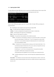
Please refer to the USB 2.0 header (as below procedures for ASRock motherboard with CIR header. Connect the front USB cable to below , pin 1-5) and the CIR header. Please make sure the wire assignments and the USB_PWR PP+ ... correctly. 1 23 45 GND IRTX IRRX ATX+5VSB Step3. Boot up your system and install Multi-Angle CIR Receiver to the USB 2.0 header on ASRock motherboard. Step1. Execute ASRock support CD and install CIR Driver. (It is listed at [Enabled]. (Advanced -> Super IO Configuration -> CIR Controller -> [Enabled]) If you cannot find this option...
Please refer to the USB 2.0 header (as below procedures for ASRock motherboard with CIR header. Connect the front USB cable to below , pin 1-5) and the CIR header. Please make sure the wire assignments and the USB_PWR PP+ ... correctly. 1 23 45 GND IRTX IRRX ATX+5VSB Step3. Boot up your system and install Multi-Angle CIR Receiver to the USB 2.0 header on ASRock motherboard. Step1. Execute ASRock support CD and install CIR Driver. (It is listed at [Enabled]. (Advanced -> Super IO Configuration -> CIR Controller -> [Enabled]) If you cannot find this option...

User Manual
Page 27
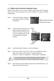
...-Plug function. Please install it on the market. 3. Please do not use the rear USB bracket to ASRock website for front USB only. Please refer to connect it before you boot the system. * ASRock Smart Remote is only supported by some of the front USB port can receive the multi-direction infrared... signals (top, down and front), which is compatible with most of the chassis on the rear panel. 3 CIR sensors in different angles 1. Only one of ASRock motherboards. Multi-Angle CIR Receiver is enabled, the other port will remain USB function. 2. When the CIR function is used for the...
...-Plug function. Please install it on the market. 3. Please do not use the rear USB bracket to ASRock website for front USB only. Please refer to connect it before you boot the system. * ASRock Smart Remote is only supported by some of the front USB port can receive the multi-direction infrared... signals (top, down and front), which is compatible with most of the chassis on the rear panel. 3 CIR sensors in different angles 1. Only one of ASRock motherboards. Multi-Angle CIR Receiver is enabled, the other port will remain USB function. 2. When the CIR function is used for the...

User Manual
Page 29
...USB_PWR P-7 P+7 GND DUMMY 1 GND P+6 P-6 USB_PWR Besides four default USB 2.0 ports on the I /O panel, there is one USB 3.0 header on this motherboard. This USB 3.0 header can support two USB 2.0 ports. USB 3.0 Header (19-pin USB3_0_1) (see p.14, No. 13) SATA3_2 SATA3_4 SATA3_1 SATA3_3 These ... Placing jumper caps over these headers and connectors. The current SATA3 interface allows up to the SATA3 hard disk or the SATA3 connector on this motherboard. Each USB 2.0 header can support two USB 3.0 ports. Serial ATA3 Connectors (SATA3_1: see p.14, No. 14) (SATA3_2: see p....
...USB_PWR P-7 P+7 GND DUMMY 1 GND P+6 P-6 USB_PWR Besides four default USB 2.0 ports on the I /O panel, there is one USB 3.0 header on this motherboard. This USB 3.0 header can support two USB 2.0 ports. USB 3.0 Header (19-pin USB3_0_1) (see p.14, No. 13) SATA3_2 SATA3_4 SATA3_1 SATA3_3 These ... Placing jumper caps over these headers and connectors. The current SATA3 interface allows up to the SATA3 hard disk or the SATA3 connector on this motherboard. Each USB 2.0 header can support two USB 3.0 ports. Serial ATA3 Connectors (SATA3_1: see p.14, No. 14) (SATA3_2: see p....


