
User Manual
Page 3
...Installation of CPU Fan and Heatsink 18 2.3 Installation of Memory Modules (DIMM 19 2.4 Expansion Slot (PCI Express Slot 20 2.5 Dual Graphics Operation Guide 21 2.6 Dual Monitor and Surround Display Features 23 2.7 ASRock Smart Remote Installation Guide 26 2.8 Jumpers Setup 28 2.9 Onboard Headers and Connectors 29 2.10 Serial ATA3 (SATA3)... Windows® 8 / 8 64-bit / 7 / 7 64-bit / VistaTM / VistaTM 64-bit Without RAID Functions 37 3 Introduction 5 1.1 Package Contents 5 1.2 Specifications 6 1.3 Unique Features 10 1.4 Motherboard Layout 14 1.5 I/O Panel 15 2. Contents 1.
...Installation of CPU Fan and Heatsink 18 2.3 Installation of Memory Modules (DIMM 19 2.4 Expansion Slot (PCI Express Slot 20 2.5 Dual Graphics Operation Guide 21 2.6 Dual Monitor and Surround Display Features 23 2.7 ASRock Smart Remote Installation Guide 26 2.8 Jumpers Setup 28 2.9 Onboard Headers and Connectors 29 2.10 Serial ATA3 (SATA3)... Windows® 8 / 8 64-bit / 7 / 7 64-bit / VistaTM / VistaTM 64-bit Without RAID Functions 37 3 Introduction 5 1.1 Package Contents 5 1.2 Specifications 6 1.3 Unique Features 10 1.4 Motherboard Layout 14 1.5 I/O Panel 15 2. Contents 1.

User Manual
Page 14
1.4 Motherboard Layout 12 3 CPU_FAN1 CPU_FAN2 25 CI1 1 Ps2 USB 2.0 Keyboard T: USB0 B: USB1 eSATA3_1 ...USB3_0_1 RoHS 64Mb BIOS Front USB 3.0 AMD A75 FCH (Hudson-D3) Top: Center: FRONT Bottom: MIC IN HD_AUDIO1 FM2A75M-ITX Chipset 1 PCIE1 22 21 20 19 18 17 16 1 CPU Fan Connector (CPU_FAN1) 2 CPU Fan Connector (CPU_FAN2) 3 ATX Power Connector (ATXPWR1...Controller 17 SPI Flash Memory (64Mb) 18 PCI Express 2.0 x16 Slot (PCIE1) 19 USB 3.0 Header (USB3_0_1) 20 ATX 12V Power Connector (ATX12V1) 21 Front Panel Audio Header (HD_AUDIO1) 22 HDMI_SPDIF Header (HDMI_SPDIF1) 23 Clear ...
1.4 Motherboard Layout 12 3 CPU_FAN1 CPU_FAN2 25 CI1 1 Ps2 USB 2.0 Keyboard T: USB0 B: USB1 eSATA3_1 ...USB3_0_1 RoHS 64Mb BIOS Front USB 3.0 AMD A75 FCH (Hudson-D3) Top: Center: FRONT Bottom: MIC IN HD_AUDIO1 FM2A75M-ITX Chipset 1 PCIE1 22 21 20 19 18 17 16 1 CPU Fan Connector (CPU_FAN1) 2 CPU Fan Connector (CPU_FAN2) 3 ATX Power Connector (ATXPWR1...Controller 17 SPI Flash Memory (64Mb) 18 PCI Express 2.0 x16 Slot (PCIE1) 19 USB 3.0 Header (USB3_0_1) 20 ATX 12V Power Connector (ATX12V1) 21 Front Panel Audio Header (HD_AUDIO1) 22 HDMI_SPDIF Header (HDMI_SPDIF1) 23 Clear ...

User Manual
Page 20
...the card before you intend to the chassis with the slot and press firmly until the card is completely seated on this motherboard. Before installing the expansion card, please make necessary hardware settings for PCI Express x16 lane width graphics cards. Step 3. Replace the ...system cover. 20 Step 5. Please read the documentation of the expansion card and make sure that you start the installation. Installing an expansion card Step 1. Remove the system unit cover (if your motherboard is unplugged. Remove the bracket facing the slot that...
...the card before you intend to the chassis with the slot and press firmly until the card is completely seated on this motherboard. Before installing the expansion card, please make necessary hardware settings for PCI Express x16 lane width graphics cards. Step 3. Replace the ...system cover. 20 Step 5. Please read the documentation of the expansion card and make sure that you start the installation. Installing an expansion card Step 1. Remove the system unit cover (if your motherboard is unplugged. Remove the bracket facing the slot that...

User Manual
Page 24
... the display icons to positions representing the physical setup of the multi-monitor according to set up a multi-monitor display. Surround Display Feature This motherboard supports surround display upgrade. Repeat steps A through C for details. 2. Please refer to the following steps to the steps below. Click the ... the UEFI setup, the default value of the add-on PCI Express VGA cards on the I/O panel. Please refer to page 20 for proper expansion card installation procedures for the display icon identified by the number three to this monitor". Then connect other monitor cables...
... the display icons to positions representing the physical setup of the multi-monitor according to set up a multi-monitor display. Surround Display Feature This motherboard supports surround display upgrade. Repeat steps A through C for details. 2. Please refer to the following steps to the steps below. Click the ... the UEFI setup, the default value of the add-on PCI Express VGA cards on the I/O panel. Please refer to page 20 for proper expansion card installation procedures for the display icon identified by the number three to this monitor". Then connect other monitor cables...

User Manual
Page 32
.... HDMI_SPDIF header, providing SPDIF audio output to HDMI VGA card, allows the system to this motherboard provides 24-pin ATX power connector, it can still work if you adopt a traditional 20-pin ATX power supply. This feature requires a chassis with Pin 1 and Pin 13. 24... 13 20-Pin ATX Power Supply Installation 12 1 ATX 12V Power Connector (4-pin ATX12V1) (see p.14, No. 20) HDMI_SPDIF Header (2-pin HDMI_SPDIF1) (see p.14, No. 25) 1 GND Signal This motherboard supports CASE OPEN detection feature that detects if the chassis...
.... HDMI_SPDIF header, providing SPDIF audio output to HDMI VGA card, allows the system to this motherboard provides 24-pin ATX power connector, it can still work if you adopt a traditional 20-pin ATX power supply. This feature requires a chassis with Pin 1 and Pin 13. 24... 13 20-Pin ATX Power Supply Installation 12 1 ATX 12V Power Connector (4-pin ATX12V1) (see p.14, No. 20) HDMI_SPDIF Header (2-pin HDMI_SPDIF1) (see p.14, No. 25) 1 GND Signal This motherboard supports CASE OPEN detection feature that detects if the chassis...
Quick Installation Guide
Page 2
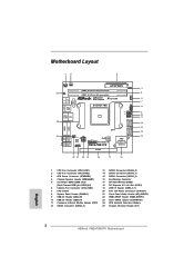
...1 RoHS 64Mb BIOS AMD AUDIO CODEC USB3_0_1 A75 FCH Front USB 3.0 (Hudson-D3) Top: Center: FRONT Bottom: MIC IN HD_AUDIO1 FM2A75M-ITX Chipset 1 PCIE1 22 21 20 19 18 17 16 1 CPU Fan Connector (CPU_FAN1) 2 CPU Fan Connector (CPU_FAN2) 3 ATX Power Connector (ATXPWR1) 4 Chassis... 2.0 x16 Slot (PCIE1) 19 USB 3.0 Header (USB3_0_1) 20 ATX 12V Power Connector (ATX12V1) 21 Front Panel Audio Header (HD_AUDIO1) 22 HDMI_SPDIF Header (HDMI_SPDIF1) 23 Clear CMOS Jumper (CLRCMOS1) 24 CPU Heatsink Retention Module 25 Chassis Intrusion Header (CI1) English 2 ASRock FM2A75M-ITX Motherboard
...1 RoHS 64Mb BIOS AMD AUDIO CODEC USB3_0_1 A75 FCH Front USB 3.0 (Hudson-D3) Top: Center: FRONT Bottom: MIC IN HD_AUDIO1 FM2A75M-ITX Chipset 1 PCIE1 22 21 20 19 18 17 16 1 CPU Fan Connector (CPU_FAN1) 2 CPU Fan Connector (CPU_FAN2) 3 ATX Power Connector (ATXPWR1) 4 Chassis... 2.0 x16 Slot (PCIE1) 19 USB 3.0 Header (USB3_0_1) 20 ATX 12V Power Connector (ATX12V1) 21 Front Panel Audio Header (HD_AUDIO1) 22 HDMI_SPDIF Header (HDMI_SPDIF1) 23 Clear CMOS Jumper (CLRCMOS1) 24 CPU Heatsink Retention Module 25 Chassis Intrusion Header (CI1) English 2 ASRock FM2A75M-ITX Motherboard

Quick Installation Guide
Page 20
... PRESENCE# MIC_RET OUT_RET 1 OUT2_L J_SENSE OUT2_R MIC2_R MIC2_L This is an interface for HD audio panel only. PWRBTN (Power Switch): Connect to perform a normal restart. 20 ASRock FM2A75M-ITX Motherboard Front Panel Audio Header (9-pin HD_AUDIO1) (see p.2 No. 8) This header accommodates several system front panel functions. C. You may configure the way to connect...
... PRESENCE# MIC_RET OUT_RET 1 OUT2_L J_SENSE OUT2_R MIC2_R MIC2_L This is an interface for HD audio panel only. PWRBTN (Power Switch): Connect to perform a normal restart. 20 ASRock FM2A75M-ITX Motherboard Front Panel Audio Header (9-pin HD_AUDIO1) (see p.2 No. 8) This header accommodates several system front panel functions. C. You may configure the way to connect...

Quick Installation Guide
Page 22
...p.2 No. 22) 1 GND SPDIFOUT Please connect an ATX 12V power supply to this motherboard provides 24-pin ATX power connector, it can still work if you adopt a traditional 20-pin ATX power supply. HDMI_SPDIF header, providing SPDIF audio output to HDMI VGA card, ... 20) HDMI_SPDIF Header (2-pin HDMI_SPDIF1) (see p.2, No. 25) 1 GND Signal This motherboard supports CASE OPEN detection feature that detects if the chassis cover has been removed. Please connect the HDMI_SPDIF connector of HDMI VGA card to connect HDMI Digital TV/ projector/LCD devices. English 22 ASRock FM2A75M-ITX Motherboard
...p.2 No. 22) 1 GND SPDIFOUT Please connect an ATX 12V power supply to this motherboard provides 24-pin ATX power connector, it can still work if you adopt a traditional 20-pin ATX power supply. HDMI_SPDIF header, providing SPDIF audio output to HDMI VGA card, ... 20) HDMI_SPDIF Header (2-pin HDMI_SPDIF1) (see p.2, No. 25) 1 GND Signal This motherboard supports CASE OPEN detection feature that detects if the chassis cover has been removed. Please connect the HDMI_SPDIF connector of HDMI VGA card to connect HDMI Digital TV/ projector/LCD devices. English 22 ASRock FM2A75M-ITX Motherboard

Quick Installation Guide
Page 104
ATX 24 (24 핀 ATXPWR1) (2 3 12 ATX 13 1 24 핀 ATX 20 핀 ATX 20 핀 ATX Pin 1 과 Pin 13 24 13 ATX 12V (4 핀 ATX12V1) (2 20 20 핀 ATX 12 1 ATX 12V HDMI_SPDIF 헤더 (2 핀 HDMI_SPDIF1) (2 22 (2 핀 CI1) (2 25 1 GND SPDIFOUT 1 GND Signal HDMI VGA 카드에 SPDIF HDMI_SPDIF HDMI 디지털 TV LCD HDMI VGA 카드의 HDMI_SPDIF 한 국 어 104 ASRock FM2A75M-ITX Motherboard
ATX 24 (24 핀 ATXPWR1) (2 3 12 ATX 13 1 24 핀 ATX 20 핀 ATX 20 핀 ATX Pin 1 과 Pin 13 24 13 ATX 12V (4 핀 ATX12V1) (2 20 20 핀 ATX 12 1 ATX 12V HDMI_SPDIF 헤더 (2 핀 HDMI_SPDIF1) (2 22 (2 핀 CI1) (2 25 1 GND SPDIFOUT 1 GND Signal HDMI VGA 카드에 SPDIF HDMI_SPDIF HDMI 디지털 TV LCD HDMI VGA 카드의 HDMI_SPDIF 한 국 어 104 ASRock FM2A75M-ITX Motherboard

Quick Installation Guide
Page 114
...12500;ン ATX 20 ピン ATX 20 ピン ATX 1 13 24 13 20 ピン ATX 12 1 ATX 12V 4 ピン ATX12V1 20 を参照...; HDMI_SPDIF ヘッダ (2- ピン HDMI_SPDIF1 22 を参照 1 GND SPDIFOUT CPU に Vcore ATX 12V HDMI_SPDIF SPDIF HDMI VGA HDMI TV LCD HDMI VGA HDMI_SPDIF 日本語 114 ASRock FM2A75M-ITX Motherboard
...12500;ン ATX 20 ピン ATX 20 ピン ATX 1 13 24 13 20 ピン ATX 12 1 ATX 12V 4 ピン ATX12V1 20 を参照...; HDMI_SPDIF ヘッダ (2- ピン HDMI_SPDIF1 22 を参照 1 GND SPDIFOUT CPU に Vcore ATX 12V HDMI_SPDIF SPDIF HDMI VGA HDMI TV LCD HDMI VGA HDMI_SPDIF 日本語 114 ASRock FM2A75M-ITX Motherboard

Quick Installation Guide
Page 124
24-pin ATX 20-pin ATX 20-pin ATX Pin 1 和 Pin 13 24 13 ATX 12V 接頭 (4 針 ATX12V1) ( 見第 2 頁第 20 項 ) HDMI_SPDIF 接頭 (2 針 HDMI_SPDIF1) ( 見第 2 頁第 22 項 ) 20-Pin ATX 12 1 ATX 12V 1 GND SPDIFOUT HDMI_SPDIF SPDIF HDMI HDMI HDMI 顯卡的 HDMI_SPDIF (2 針 CI1) ( 見第 2 頁第 25 項 ) 1 GND Signal 簡體中文 124 ASRock FM2A75M-ITX Motherboard
24-pin ATX 20-pin ATX 20-pin ATX Pin 1 和 Pin 13 24 13 ATX 12V 接頭 (4 針 ATX12V1) ( 見第 2 頁第 20 項 ) HDMI_SPDIF 接頭 (2 針 HDMI_SPDIF1) ( 見第 2 頁第 22 項 ) 20-Pin ATX 12 1 ATX 12V 1 GND SPDIFOUT HDMI_SPDIF SPDIF HDMI HDMI HDMI 顯卡的 HDMI_SPDIF (2 針 CI1) ( 見第 2 頁第 25 項 ) 1 GND Signal 簡體中文 124 ASRock FM2A75M-ITX Motherboard

Quick Installation Guide
Page 134
24-pin ATX 20-pin ATX 20-pin ATX Pin 1 和 Pin 13 24 13 20-Pin ATX 12 1 ATX 12V (4 針 ATX12V1) ( 見第 2 頁第 20 項 ) HDMI_SPDIF 接頭 (2 針 HDMI_SPDIF1) ( 見第 2 頁第 22 項 ) 1 GND SPDIFOUT ATX 12V HDMI_SPDIF SPDIF H D M I HDMI HDMI HDMI_SPDIF (2 針 CI1) ( 見第 2 頁第 25 項 ) 1 GND Signal 繁體中文 134 ASRock FM2A75M-ITX Motherboard
24-pin ATX 20-pin ATX 20-pin ATX Pin 1 和 Pin 13 24 13 20-Pin ATX 12 1 ATX 12V (4 針 ATX12V1) ( 見第 2 頁第 20 項 ) HDMI_SPDIF 接頭 (2 針 HDMI_SPDIF1) ( 見第 2 頁第 22 項 ) 1 GND SPDIFOUT ATX 12V HDMI_SPDIF SPDIF H D M I HDMI HDMI HDMI_SPDIF (2 針 CI1) ( 見第 2 頁第 25 項 ) 1 GND Signal 繁體中文 134 ASRock FM2A75M-ITX Motherboard

