User Manual
Page 1
Core 100 Series User Manual Version 1.0 Published April 2010 Copyright©2010 ASRock INC. All rights reserved. 1
Core 100 Series User Manual Version 1.0 Published April 2010 Copyright©2010 ASRock INC. All rights reserved. 1
User Manual
Page 2
...or consequential damages (including damages for loss of profits, loss of business, loss of data, interruption of business and the like), even if ASRock has been advised of the possibility of such damages arising from any kind, either expressed or implied, including but not limited to the implied... may or may not be registered trademarks or copyrights of their respective companies, and are furnished for backup purpose, without written consent of ASRock Inc. Copyright Notice: No part of this manual may be reproduced, transcribed, transmitted, or translated in any language, in any form ...
...or consequential damages (including damages for loss of profits, loss of business, loss of data, interruption of business and the like), even if ASRock has been advised of the possibility of such damages arising from any kind, either expressed or implied, including but not limited to the implied... may or may not be registered trademarks or copyrights of their respective companies, and are furnished for backup purpose, without written consent of ASRock Inc. Copyright Notice: No part of this manual may be reproduced, transcribed, transmitted, or translated in any language, in any form ...

User Manual
Page 3
Do not use this product in the documentation before cleaning the system. Set up your system. Do not block or cover these openings. Use this product near water or a heated source such as a result of attempting to disassemble/reassemble the system or modifying the hardware configuration. 3 Openings on it is important that you use • • • Do not walk on the power cord or allow anything to meet the latest standards of safety for information technology equipment. When the system is designed and tested to rest on the chassis are for ventilation. Always ...
Do not use this product in the documentation before cleaning the system. Set up your system. Do not block or cover these openings. Use this product near water or a heated source such as a result of attempting to disassemble/reassemble the system or modifying the hardware configuration. 3 Openings on it is important that you use • • • Do not walk on the power cord or allow anything to meet the latest standards of safety for information technology equipment. When the system is designed and tested to rest on the chassis are for ventilation. Always ...
User Manual
Page 4
Check local regulations for lithium-ion batteries) CAUTION! Dispose of electronic products. Do not use or expose this product around magnetic fields as magnetic interference may result in municipal waste. Do not block the air vents to this product to disassemble the optical drive. Danger of the product. Do not expose this product or impede the airflow in an unstable position. CAUTION: Invisible laser radiation when open. Do not attempt to high levels of the crossed out wheeled bin indicates that the product (electrical and electronic equipment) should not be placed in ...
Check local regulations for lithium-ion batteries) CAUTION! Dispose of electronic products. Do not use or expose this product around magnetic fields as magnetic interference may result in municipal waste. Do not block the air vents to this product to disassemble the optical drive. Danger of the product. Do not expose this product or impede the airflow in an unstable position. CAUTION: Invisible laser radiation when open. Do not attempt to high levels of the crossed out wheeled bin indicates that the product (electrical and electronic equipment) should not be placed in ...

User Manual
Page 5
... Installation ...System Components Reinstallation ...Installing Second HDD ...Driver Installation ...UTILITY MEMU ...6.1 Instant Boot ...6.1.1 Introduction ...6.1.2 Installation ...6.2 ASRock OC Tuner ...6.2.1 Introduction ...6.2.2 Installation ...6.3 CyberLink DVD Suite free bundle (Trial version, including PowerDVD, PowerDirector, etc) ...6.4... free bundle (Trial version) ...6.5 THX TruStudio PRO Software free bundle ...6.6 ASRock AIWI Utility ...6.7 The best Apple charge companion - ASRock APP Charger ...7.1 Introduction ...7.1.1 BIOS Menu Bar ...7.1.2 Navigation Keys ...7.2 Main Screen...
... Installation ...System Components Reinstallation ...Installing Second HDD ...Driver Installation ...UTILITY MEMU ...6.1 Instant Boot ...6.1.1 Introduction ...6.1.2 Installation ...6.2 ASRock OC Tuner ...6.2.1 Introduction ...6.2.2 Installation ...6.3 CyberLink DVD Suite free bundle (Trial version, including PowerDVD, PowerDirector, etc) ...6.4... free bundle (Trial version) ...6.5 THX TruStudio PRO Software free bundle ...6.6 ASRock AIWI Utility ...6.7 The best Apple charge companion - ASRock APP Charger ...7.1 Introduction ...7.1.1 BIOS Menu Bar ...7.1.2 Navigation Keys ...7.2 Main Screen...

User Manual
Page 6
7.5 Hardware Health Event Monitoring Screen ...7.6 Boot Screen ...7.6.1 Boot Settings Configuration ...7.7 Security Screen ...7.8 Exit Screen ...8.1 Install Operating System ...8.2 Support CD Information ...8.2.1 Running Support CD ...8.2.2 Drivers Menu ...8.2.3 Utilities Menu ...8.2.4 Contact Information ... 48 48 49 50 51 52 52 52 52 52 52 8 Software Support ...52 6
7.5 Hardware Health Event Monitoring Screen ...7.6 Boot Screen ...7.6.1 Boot Settings Configuration ...7.7 Security Screen ...7.8 Exit Screen ...8.1 Install Operating System ...8.2 Support CD Information ...8.2.1 Running Support CD ...8.2.2 Drivers Menu ...8.2.3 Utilities Menu ...8.2.4 Contact Information ... 48 48 49 50 51 52 52 52 52 52 52 8 Software Support ...52 6

User Manual
Page 7
...and step-bystep guide to DVI Adapter One Anti-Slip Pad Remote Controller (Core 100HT / Core 100HT-BD) SATA and Power Cables 7 www.asrock.com/support/index.asp 1.1 Package Contents ASRock Core 100 Series ASRock Support CD ASRock Quick Start Guide One AC Power Cord One AC/DC Adapter One HDMI ...about the model you require technical support related to this product, please visit our website for purchasing ASRock Core 100 Series, a reliable product produced under ASRock's consistently stringent quality control. Chapter 3 and 4 contain the configuration guide to quality and endurance.
...and step-bystep guide to DVI Adapter One Anti-Slip Pad Remote Controller (Core 100HT / Core 100HT-BD) SATA and Power Cables 7 www.asrock.com/support/index.asp 1.1 Package Contents ASRock Core 100 Series ASRock Support CD ASRock Quick Start Guide One AC Power Cord One AC/DC Adapter One HDMI ...about the model you require technical support related to this product, please visit our website for purchasing ASRock Core 100 Series, a reliable product produced under ASRock's consistently stringent quality control. Chapter 3 and 4 contain the configuration guide to quality and endurance.

User Manual
Page 8
...Hot Plug function is a certain risk involved with THX TruStudio ProTM Gigabit LAN 802.11b/g/n wireless LAN (Core 100HT / Core 100HT-BD) Support MCE function (Core 100HT / Core 100HT-BD) 90W/19V Adapter 195mm(W)x70mm(H)x186m(L) 2.5L For barebone system, it may affect your system stability, or... WinXP, please disable the BIOS option "USB2.0 Rate Matching Hub" to 8GB Intel® HD Graphics 2.5" HDD, support second 2.5" HDD DVD Super Multi (Core 100 / Core 100HT) BD Combo*2 (Core 100HT-BD) 2 x USB3.0, 1 x Microphone, 1 x Earphone 1 x HDMI, 1 x D-Sub VGA, 6 x USB2.0, 1 x S/PDIF, 1 x eSATAII*3 ...
...Hot Plug function is a certain risk involved with THX TruStudio ProTM Gigabit LAN 802.11b/g/n wireless LAN (Core 100HT / Core 100HT-BD) Support MCE function (Core 100HT / Core 100HT-BD) 90W/19V Adapter 195mm(W)x70mm(H)x186m(L) 2.5L For barebone system, it may affect your system stability, or... WinXP, please disable the BIOS option "USB2.0 Rate Matching Hub" to 8GB Intel® HD Graphics 2.5" HDD, support second 2.5" HDD DVD Super Multi (Core 100 / Core 100HT) BD Combo*2 (Core 100HT-BD) 2 x USB3.0, 1 x Microphone, 1 x Earphone 1 x HDMI, 1 x D-Sub VGA, 6 x USB2.0, 1 x S/PDIF, 1 x eSATAII*3 ...
User Manual
Page 9
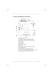
Northbridge heatsink 2. J1 jumper: For second HDD SATA power cable 3. ATX5V output power connector for slim ODD & 2.5" HDD 13. Infrared module header 8. 1.3 System Motherboard Components HM55-HT Design in Taipei PCIE1 1. SATA connector: For second HDD SATA data cable 4. SATA connector: For ODD SATA data cable 12. Fan connector 7. Memory socket 6. Clear CMOS jumper 11. SATA connector: For HDD SATA data cable EuP Ready RoHS DDR3_A1FSB800 DDR3_B1 9 Fan connector 5. CPU socket 9. Mini-PCI Express expansion slot: For WiFi module 10.
Northbridge heatsink 2. J1 jumper: For second HDD SATA power cable 3. ATX5V output power connector for slim ODD & 2.5" HDD 13. Infrared module header 8. 1.3 System Motherboard Components HM55-HT Design in Taipei PCIE1 1. SATA connector: For second HDD SATA data cable 4. SATA connector: For ODD SATA data cable 12. Fan connector 7. Memory socket 6. Clear CMOS jumper 11. SATA connector: For HDD SATA data cable EuP Ready RoHS DDR3_A1FSB800 DDR3_B1 9 Fan connector 5. CPU socket 9. Mini-PCI Express expansion slot: For WiFi module 10.
User Manual
Page 10
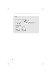
SATA and Power Connections Connect to ODD SATA & Power Connections HDD ODD Connect to HDD Connect to SATA Connector (11) Connect to ATX5V Power Connector (12) Connect to SATA Connector (13) 2. Fan Connection Fan connector Ground +12V Rotation Fan connector Ground +5V Rotation item 4 item 6 10 NOTE. 1.
SATA and Power Connections Connect to ODD SATA & Power Connections HDD ODD Connect to HDD Connect to SATA Connector (11) Connect to ATX5V Power Connector (12) Connect to SATA Connector (13) 2. Fan Connection Fan connector Ground +12V Rotation Fan connector Ground +5V Rotation item 4 item 6 10 NOTE. 1.
User Manual
Page 11
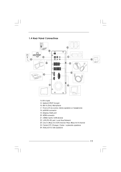
1.4 Rear Panel Connectinos 25 14 15 16 17 24 23 22 MP3 S / PDIF eSATA 18 21 eSATAII HDMI 20 19 SONY 14. USB2.0 ports: USB devices 22. Mic In (Pink): Microphone 17. Display (VGA) port 20. Line In (Blue) for side speakers 11 Center/LFE (Orange): Center / subwoofer speakers 25. Side port for 2/4/6 channel; HDMI connector 21. eSATAII connector 19. Rear (Blue) for 8 channel 24. DC-In jack 15. Optical S/PDIF Out port 16. Front L/R Out (Lime): Stereo speakers or headphones 18. LAN (RJ-45) port: Local Area Network 23.
1.4 Rear Panel Connectinos 25 14 15 16 17 24 23 22 MP3 S / PDIF eSATA 18 21 eSATAII HDMI 20 19 SONY 14. USB2.0 ports: USB devices 22. Mic In (Pink): Microphone 17. Display (VGA) port 20. Line In (Blue) for side speakers 11 Center/LFE (Orange): Center / subwoofer speakers 25. Side port for 2/4/6 channel; HDMI connector 21. eSATAII connector 19. Rear (Blue) for 8 channel 24. DC-In jack 15. Optical S/PDIF Out port 16. Front L/R Out (Lime): Stereo speakers or headphones 18. LAN (RJ-45) port: Local Area Network 23.
User Manual
Page 12
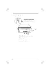
Remove the screws on the backside. 2. Drive activity indicator 29. Slide the top panel backwards. Power ON/OFF button with status indicator 28. USB3.0 ports: USB devices 12 eSATAII HDMI 26 27 31 30 29 28 26. Microphone 31. Optical Disc Drive 27. Earphone 30. 1.5 System Chassis Opening the system chassis 1.
Remove the screws on the backside. 2. Drive activity indicator 29. Slide the top panel backwards. Power ON/OFF button with status indicator 28. USB3.0 ports: USB devices 12 eSATAII HDMI 26 27 31 30 29 28 26. Microphone 31. Optical Disc Drive 27. Earphone 30. 1.5 System Chassis Opening the system chassis 1.
User Manual
Page 13
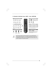
1.6 R emote Controller (Core 100HT / Core 100HT -BD) Remote 100HT-BD) Some remote controller functions listed above are only available with the system, you adopt are not allowed to meet MCE standards. 13 This product is designed to use these functions. If the hardware equipments you are not compatible with the relative hardware equipments.
1.6 R emote Controller (Core 100HT / Core 100HT -BD) Remote 100HT-BD) Some remote controller functions listed above are only available with the system, you adopt are not allowed to meet MCE standards. 13 This product is designed to use these functions. If the hardware equipments you are not compatible with the relative hardware equipments.
User Manual
Page 14
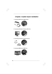
Chapter 2 System Quick Installation 1. Connecting the Network (LAN (RJ-45) Port) 4. Connecting VGA Monitor (Display (VGA) Port) 3. Connecting HDMI Device (HDMI Port) 14 Connecting USB Devices (USB2.0 Ports) 2.
Chapter 2 System Quick Installation 1. Connecting the Network (LAN (RJ-45) Port) 4. Connecting VGA Monitor (Display (VGA) Port) 3. Connecting HDMI Device (HDMI Port) 14 Connecting USB Devices (USB2.0 Ports) 2.
User Manual
Page 15
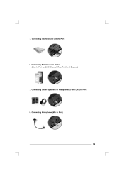
Rear Port for 2/4/6 Channel; Connecting eSATA Device (eSATA Port) 6. Connecting Stereo Speakers or Headphones (Front L/R Out Port) 8. 5. Connecting External Audio Device (Line In Port for 8 Channel) 7. Connecting Microphone (Mic In Port) 15
Rear Port for 2/4/6 Channel; Connecting eSATA Device (eSATA Port) 6. Connecting Stereo Speakers or Headphones (Front L/R Out Port) 8. 5. Connecting External Audio Device (Line In Port for 8 Channel) 7. Connecting Microphone (Mic In Port) 15
User Manual
Page 16
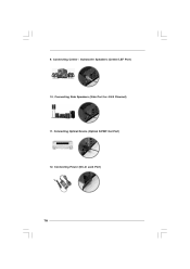
9. Connecting Power (DC-In Jack Port) 16 Connecting Optical Device (Optical S/PDIF Out Port) 12. Connecting Center / Subwoofer Speakers (Center/LEF Port) 10. Connecting Side Speakers (Side Port for 4/6/8 Channel) 11.
9. Connecting Power (DC-In Jack Port) 16 Connecting Optical Device (Optical S/PDIF Out Port) 12. Connecting Center / Subwoofer Speakers (Center/LEF Port) 10. Connecting Side Speakers (Side Port for 4/6/8 Channel) 11.
User Manual
Page 17
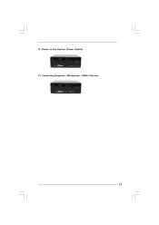
Connecting Earphone / Microphone / USB3.0 Devices 17 Power on the System (Power Switch) 14. 13.
Connecting Earphone / Microphone / USB3.0 Devices 17 Power on the System (Power Switch) 14. 13.
User Manual
Page 18
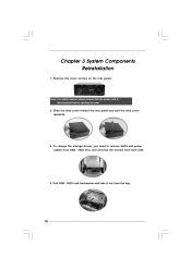
Remove the cover screws on the rear panel. Slide the side cover toward the rear panel and pull the side cover upwards. 3. Pull ODD / HDD rack backwards and take it out from both side. 4. Note: For safety reasons, please ensure that the power cord is disconnected before opening the case. 2. To change the storage drives, you need to remove SATA and power cables from ODD / HDD first, and unscrew the screws from the bay. 18 Chapter 3 System Components Reinstallation 1.
Remove the cover screws on the rear panel. Slide the side cover toward the rear panel and pull the side cover upwards. 3. Pull ODD / HDD rack backwards and take it out from both side. 4. Note: For safety reasons, please ensure that the power cord is disconnected before opening the case. 2. To change the storage drives, you need to remove SATA and power cables from ODD / HDD first, and unscrew the screws from the bay. 18 Chapter 3 System Components Reinstallation 1.
User Manual
Page 19
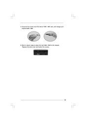
Unscrew the screws from the side of ODD / HDD rack, and change your required ODD / HDD. 6. Replace the side cover and fasten the screws. 19 5. Refer to above steps to place the new ODD / HDD to the chassis.
Unscrew the screws from the side of ODD / HDD rack, and change your required ODD / HDD. 6. Replace the side cover and fasten the screws. 19 5. Refer to above steps to place the new ODD / HDD to the chassis.
User Manual
Page 20
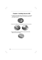
Replace the rack to 4, and remove the ODD and the first HDD in advance. To install the second HDD, please follow above step 1 to the chassis. 20 Place the ODD to the rack and fasten the screws from both side. 3. Place the first HDD to the rack and fasten the screws from both side. Then fasten the screws of the second HDD to the rack. 2. Chapter 4 Installing Second HDD 1.
Replace the rack to 4, and remove the ODD and the first HDD in advance. To install the second HDD, please follow above step 1 to the chassis. 20 Place the ODD to the rack and fasten the screws from both side. 3. Place the first HDD to the rack and fasten the screws from both side. Then fasten the screws of the second HDD to the rack. 2. Chapter 4 Installing Second HDD 1.
