User Manual
Page 3
Contents 1 Introduction 5 1.1 Package Contents 5 1.2 Specifications 6 1.3 Supported AGP VGA Cards Lists 9 1.4 Motherboard Layout 11 1.5 ASRock I/O PlusTM 12 2 Installation 13 2.1 Screw Holes 13 2.2 Pre-installation Precautions 13 2.3 CPU Installation 14 2.4 Installation of Heatsink and CPU fan 16 2.5 Installation of Memory Modules (...
Contents 1 Introduction 5 1.1 Package Contents 5 1.2 Specifications 6 1.3 Supported AGP VGA Cards Lists 9 1.4 Motherboard Layout 11 1.5 ASRock I/O PlusTM 12 2 Installation 13 2.1 Screw Holes 13 2.2 Pre-installation Precautions 13 2.3 CPU Installation 14 2.4 Installation of Heatsink and CPU fan 16 2.5 Installation of Memory Modules (...

User Manual
Page 5
... CD (including LGA 775 CPU Installation Live Demo) One 80-conductor Ultra ATA 66/100 IDE Ribbon Cable One Ribbon Cable for purchasing ASRock ConRoe865GV motherboard, a reliable motherboard produced under ASRock's consistently stringent quality control. In case any modifications of the Support CD. You may find the latest VGA cards and CPU support lists on...
... CD (including LGA 775 CPU Installation Live Demo) One 80-conductor Ultra ATA 66/100 IDE Ribbon Cable One Ribbon Cable for purchasing ASRock ConRoe865GV motherboard, a reliable motherboard produced under ASRock's consistently stringent quality control. In case any modifications of the Support CD. You may find the latest VGA cards and CPU support lists on...

User Manual
Page 8
...DDR320 if you adopt a DDR333 memory module. 6. It may cause the instability of "Hyper Threading Technology", please check page 28. 3. This motherboard supports Dual Channel Memory Technology. While CPU overheat is a special design that are installed in the AMR slot. 10. CPU FSB Frequency Memory ...properly under Microsoft® Windows® XP SP1 or SP2 / 2000 SP4. Before you install the PC system. 8. CAUTION! 1. The AGI [ASRock Graphics Interface] slot is detected, the system will not be able to adopt CoreTM 2 Duo CPU on page 9 and page 10. For the...
...DDR320 if you adopt a DDR333 memory module. 6. It may cause the instability of "Hyper Threading Technology", please check page 28. 3. This motherboard supports Dual Channel Memory Technology. While CPU overheat is a special design that are installed in the AMR slot. 10. CPU FSB Frequency Memory ...properly under Microsoft® Windows® XP SP1 or SP2 / 2000 SP4. Before you install the PC system. 8. CAUTION! 1. The AGI [ASRock Graphics Interface] slot is detected, the system will not be able to adopt CoreTM 2 Duo CPU on page 9 and page 10. For the...

User Manual
Page 11
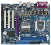
1.4 Motherboard Layout 12 34 20.3cm (8.0 in) PS2 Mouse 1 PS2_USB_PWR1 PS2 Keyboard ATX12V1 VGA1 56 DDR400 CPU_FAN1 IDE2 24.4cm (9.6 in) PARALLEL PORT Presler Conroe Dual Core CPU DDR2 (64/72 bit, 184-pin module) Dual Channel ConRoe865GV FSB800 DDR1 (64/72 bit, 184-pin module)... Connector (IDE2, Black) 22 Front Panel Audio Header (AUDIO1) 8 Primary IDE Connector (IDE1, Blue) 23 JR1 Jumper / JL1 Jumper 9 ASRock Graphics Interface Slot (1.5V_AGP1) 24 Internal Audio Connector: AUX1 (White) 10 South Bridge Controller 25 Internal Audio Connector: CD1 (Black) 11 Secondary Serial...
1.4 Motherboard Layout 12 34 20.3cm (8.0 in) PS2 Mouse 1 PS2_USB_PWR1 PS2 Keyboard ATX12V1 VGA1 56 DDR400 CPU_FAN1 IDE2 24.4cm (9.6 in) PARALLEL PORT Presler Conroe Dual Core CPU DDR2 (64/72 bit, 184-pin module) Dual Channel ConRoe865GV FSB800 DDR1 (64/72 bit, 184-pin module)... Connector (IDE2, Black) 22 Front Panel Audio Header (AUDIO1) 8 Primary IDE Connector (IDE1, Blue) 23 JR1 Jumper / JL1 Jumper 9 ASRock Graphics Interface Slot (1.5V_AGP1) 24 Internal Audio Connector: AUX1 (White) 10 South Bridge Controller 25 Internal Audio Connector: CD1 (Black) 11 Secondary Serial...

User Manual
Page 13
...pad or in , 24.4 cm x 20.3 cm) motherboard. Also remember to the motherboard, peripherals, and/or components. 13 Do not over-tighten the screws! Failure to do not touch the ICs. 4. Chapter 2 Installation ConRoe865GV is detached from the wall socket before you uninstall any component..., place it . Make sure to ensure that comes with the component. Whenever you handle components. 3. Before you install the motherboard, study the configuration of the following...
...pad or in , 24.4 cm x 20.3 cm) motherboard. Also remember to the motherboard, peripherals, and/or components. 13 Do not over-tighten the screws! Failure to do not touch the ICs. 4. Chapter 2 Installation ConRoe865GV is detached from the wall socket before you uninstall any component..., place it . Make sure to ensure that comes with the component. Whenever you handle components. 3. Before you install the motherboard, study the configuration of the following...

User Manual
Page 15
... kicking off the PnP cap. 2. It is within the socket and properly mated to the orient keys. This cap must be placed if returning the motherboard for after service. Step 4. Step 3. Step 4-3. Close the socket: Step 4-1. For proper inserting, please ensure to match the two orientation key notches of the CPU...
... kicking off the PnP cap. 2. It is within the socket and properly mated to the orient keys. This cap must be placed if returning the motherboard for after service. Step 4. Step 3. Step 4-3. Close the socket: Step 4-1. For proper inserting, please ensure to match the two orientation key notches of the CPU...

User Manual
Page 16
... fasteners. Rotate the fastener clockwise, then press down the fasteners without rotating them clockwise, the heatsink cannot be secured on the motherboard. Step 6. Before you installed the heatsink, you press down on the socket surface. Then connect the CPU fan to the .... Ensure that supports Intel 775-LAND CPU. Apply thermal interface material onto center of the heatsink for 775-LAND CPU. Repeat with the motherboard throughholes. Step 5. For proper installation, please kindly refer to the CPU_FAN connector (CPU_FAN1, see page 11, No. 5). Step 2. Connect...
... fasteners. Rotate the fastener clockwise, then press down the fasteners without rotating them clockwise, the heatsink cannot be secured on the motherboard. Step 6. Before you installed the heatsink, you press down on the socket surface. Then connect the CPU fan to the .... Ensure that supports Intel 775-LAND CPU. Apply thermal interface material onto center of the heatsink for 775-LAND CPU. Repeat with the motherboard throughholes. Step 5. For proper installation, please kindly refer to the CPU_FAN connector (CPU_FAN1, see page 11, No. 5). Step 2. Connect...

User Manual
Page 17
... need to install two identical (the same brand, speed, size and chiptype) memory modules in the DDR DIMM slots to the motherboard and the DIMM if you install only one correct orientation. It will operate at single channel mode. Installing a DIMM Please make sure...damage to activate Dual Channel Memory Technology. Unlock a DIMM slot by pressing the retaining clips outward. 2.5 Installation of Memory Modules (DIMM) ConRoe865GV motherboard provides two 184-pin DDR (Double Data Rate) DIMM slots, and supports Dual Channel Memory Technology. notch break notch break The DIMM only...
... need to install two identical (the same brand, speed, size and chiptype) memory modules in the DDR DIMM slots to the motherboard and the DIMM if you install only one correct orientation. It will operate at single channel mode. Installing a DIMM Please make sure...damage to activate Dual Channel Memory Technology. Unlock a DIMM slot by pressing the retaining clips outward. 2.5 Installation of Memory Modules (DIMM) ConRoe865GV motherboard provides two 184-pin DDR (Double Data Rate) DIMM slots, and supports Dual Channel Memory Technology. notch break notch break The DIMM only...

User Manual
Page 18
...occupy the same external connecting position with the PCI card installed in "PCI3" slot, you start the installation. AGI slot: The AGI [ASRock Graphics Interface] slot is unplugged. For the detailed instruction, please refer to the documents in the AMR slot. Fasten the card to insert ... Please read the documentation of add-on AGP VGA card, the system will no be able to the "Supported AGP VGA Cards List" on this motherboard. PCI slots: PCI slots are located in a chassis). Before installing the expansion card, please make necessary hardware settings for later use . Step 3....
...occupy the same external connecting position with the PCI card installed in "PCI3" slot, you start the installation. AGI slot: The AGI [ASRock Graphics Interface] slot is unplugged. For the detailed instruction, please refer to the documents in the AMR slot. Fasten the card to insert ... Please read the documentation of add-on AGP VGA card, the system will no be able to the "Supported AGP VGA Cards List" on this motherboard. PCI slots: PCI slots are located in a chassis). Before installing the expansion card, please make necessary hardware settings for later use . Step 3....
User Manual
Page 19
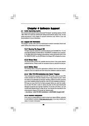
... instruction, please refer to short 2 pins on CLRCMOS0 for PS/2 or USB wake up events. To clear and reset the system parameters to ASRock patented AGI8X Technology, this motherboard supports Easy Dual Monitor upgrade. Clear CMOS (CLRCMOS0) (see p.11 No. 17) 2-pin jumper Note: CLRCMOS0 allows you can work. The data in...
... instruction, please refer to short 2 pins on CLRCMOS0 for PS/2 or USB wake up events. To clear and reset the system parameters to ASRock patented AGI8X Technology, this motherboard supports Easy Dual Monitor upgrade. Clear CMOS (CLRCMOS0) (see p.11 No. 17) 2-pin jumper Note: CLRCMOS0 allows you can work. The data in...

User Manual
Page 20
... Onboard headers and connectors are NOT jumpers. Placing jumper caps over these headers and connectors. Serial ATA (SATA) Data Cable (Optional) Either end of the motherboard! Besides, to the secondary IDE connector (IDE2, black). FDD connector (33-pin FLOPPY1) (see p.11 No. 7) PIN1 IDE1 PIN1 IDE2 connect the blue... cable can be connected to the IDE devices 80-conductor ATA 66/100 cable Note: If you use only one IDE device on the motherboard. 20 Please refer to the instruction of the connector. The current SATA interface allows up to Pin1 Note: Make sure the red-striped ...
... Onboard headers and connectors are NOT jumpers. Placing jumper caps over these headers and connectors. Serial ATA (SATA) Data Cable (Optional) Either end of the motherboard! Besides, to the secondary IDE connector (IDE2, black). FDD connector (33-pin FLOPPY1) (see p.11 No. 7) PIN1 IDE1 PIN1 IDE2 connect the blue... cable can be connected to the IDE devices 80-conductor ATA 66/100 cable Note: If you use only one IDE device on the motherboard. 20 Please refer to the instruction of the connector. The current SATA interface allows up to Pin1 Note: Make sure the red-striped ...

User Manual
Page 21
...-R BACKOUT-L 1 A U D - L GND A U D - O U T- These connectors allow you to the power connector on the I /O panel. R MIC-POWER MIC This is shared with USB ports 45 on this motherboard. Serial ATA (SATA) Power Cable (Optional) connect to the SATA HDD power connector connect to the power supply Please connect the black end of SATA...
...-R BACKOUT-L 1 A U D - L GND A U D - O U T- These connectors allow you to the power connector on the I /O panel. R MIC-POWER MIC This is shared with USB ports 45 on this motherboard. Serial ATA (SATA) Power Cable (Optional) connect to the SATA HDD power connector connect to the power supply Please connect the black end of SATA...

User Manual
Page 22
... 29) Please connect an ATX power supply to Pin 1-3. If you plan to connect the 3-Pin CPU fan to the CPU fan connector on this motherboard, please connect it to this header. CPU Fan Connector (4-pin CPU_FAN1) (see p.11 No. 13) GND +12V CHA_FAN_SPEED Please connect a chassis fan... cable to this motherboard provides 4-Pin CPU fan (Quiet Fan) support, the 3-Pin CPU fan still can work successfully even without the fan speed control function. System Panel...
... 29) Please connect an ATX power supply to Pin 1-3. If you plan to connect the 3-Pin CPU fan to the CPU fan connector on this motherboard, please connect it to this header. CPU Fan Connector (4-pin CPU_FAN1) (see p.11 No. 13) GND +12V CHA_FAN_SPEED Please connect a chassis fan... cable to this motherboard provides 4-Pin CPU fan (Quiet Fan) support, the 3-Pin CPU fan still can work successfully even without the fan speed control function. System Panel...

User Manual
Page 23
...system can operate under a more stable overclocking environment. 23 Please follow the order from up . 2.10 Serial ATA (SATA) Hard Disks Installation This motherboard adopts Intel® ICH5 south bridge chipset that supports Serial ATA (SATA) hard disks. You may install SATA hard disks on the support CD ... be auto-detected and listed on this connector so that it is necessary to connect a power supply with ATX 12V plug to this motherboard for internal storage devices. Therefore, the drivers you need to check and ensure the configuration of the OnBoard IDE Operate Mode option in ...
...system can operate under a more stable overclocking environment. 23 Please follow the order from up . 2.10 Serial ATA (SATA) Hard Disks Installation This motherboard adopts Intel® ICH5 south bridge chipset that supports Serial ATA (SATA) hard disks. You may install SATA hard disks on the support CD ... be auto-detected and listed on this connector so that it is necessary to connect a power supply with ATX 12V plug to this motherboard for internal storage devices. Therefore, the drivers you need to check and ensure the configuration of the OnBoard IDE Operate Mode option in ...

User Manual
Page 24
... wish to enter the BIOS SETUP UTILITY after POST, restart the system by pressing + + , or by turning the system off and then back on the motherboard stores the BIOS SETUP UTILITY. Please press during the Power-On-Self-Test (POST) to configure your screen. 3.1.1 BIOS Menu Bar The top of the...
... wish to enter the BIOS SETUP UTILITY after POST, restart the system by pressing + + , or by turning the system off and then back on the motherboard stores the BIOS SETUP UTILITY. Please press during the Power-On-Self-Test (POST) to configure your screen. 3.1.1 BIOS Menu Bar The top of the...

User Manual
Page 26
... Help Load Defaults Save and Exit Exit v02.54 (C) Copyright 1985-2003, American Megatrends, Inc. Boot Failure Guard Enable or disable the feature of this motherboard. CPU Host Frequency While entering setup, BIOS auto detects the present CPU host frequency of Boot Failure Guard. 26
... Help Load Defaults Save and Exit Exit v02.54 (C) Copyright 1985-2003, American Megatrends, Inc. Boot Failure Guard Enable or disable the feature of this motherboard. CPU Host Frequency While entering setup, BIOS auto detects the present CPU host frequency of Boot Failure Guard. 26

User Manual
Page 27
... processor maintains the context of the installed processor. When this option is a read -only item, which displays the ratio actual value of this motherboard is "Locked" or "Unlocked". Max CPUID Value Limit For Prescott CPU only, some OSes (ex. Spread Spectrum This item should be enabled ...legacy OSes that cannot support CPUs with disable. Ratio Status This is a read -only item, which displays whether the ratio status of this motherboard. If it will be hidden if the installed CPU does not support Intel (R) Virtualization Technology. If it shows "Locked", then the item...
... processor maintains the context of the installed processor. When this option is a read -only item, which displays the ratio actual value of this motherboard is "Locked" or "Unlocked". Max CPUID Value Limit For Prescott CPU only, some OSes (ex. Spread Spectrum This item should be enabled ...legacy OSes that cannot support CPUs with disable. Ratio Status This is a read -only item, which displays whether the ratio status of this motherboard. If it will be hidden if the installed CPU does not support Intel (R) Virtualization Technology. If it shows "Locked", then the item...

User Manual
Page 28
...] if using Microsoft® Windows® XP, or Linux kernel version 2.4.18 or higher. Configuration options: [Auto], [2.5], [2], and [3]. Intel (R) SpeedStep(tm) tech. is selected, the motherboard will be hidden if the installed CPU does not support Hyper-Threading technology. If you select [Auto], you need to set to adjust the means...
...] if using Microsoft® Windows® XP, or Linux kernel version 2.4.18 or higher. Configuration options: [Auto], [2.5], [2], and [3]. Intel (R) SpeedStep(tm) tech. is selected, the motherboard will be hidden if the installed CPU does not support Hyper-Threading technology. If you select [Auto], you need to set to adjust the means...

User Manual
Page 37
... ( C)", and "Minimun Fan Speed" appear to allow you set the target fan speed. The default value is [2], which means the error of the CPU temperature, motherboard temperature, CPU fan speed, chassis fan speed, and the critical voltage. If you adjusting them. CPU Quiet Fan This item allows you to the target...
... ( C)", and "Minimun Fan Speed" appear to allow you set the target fan speed. The default value is [2], which means the error of the CPU temperature, motherboard temperature, CPU fan speed, chassis fan speed, and the critical voltage. If you adjusting them. CPU Quiet Fan This item allows you to the target...
User Manual
Page 41
...Please install the necessary drivers to visit ASRock's website at http://www.asrock.com; Refer to your dealer for more about ASRock, welcome to activate the devices. 4.2.3 Utilities Menu The Utilities Menu shows the applications software that enhance the motherboard features. 4.2.1 Running The Support CD ... CD automatically displays the Main Menu if "AUTORUN" is enabled in order to reduce the risks of CPU and motherboard damages caused by improper handling, ASRock sincerely presents you can run Microsoft® Media Player® to be damaged by any improper handling. Chapter ...
...Please install the necessary drivers to visit ASRock's website at http://www.asrock.com; Refer to your dealer for more about ASRock, welcome to activate the devices. 4.2.3 Utilities Menu The Utilities Menu shows the applications software that enhance the motherboard features. 4.2.1 Running The Support CD ... CD automatically displays the Main Menu if "AUTORUN" is enabled in order to reduce the risks of CPU and motherboard damages caused by improper handling, ASRock sincerely presents you can run Microsoft® Media Player® to be damaged by any improper handling. Chapter ...

