User Manual
Page 3
...1 Introduction 5 1.1 Package Contents 5 1.2 Specifications 6 1.3 Supported AGP VGA Cards Lists 9 1.4 Motherboard Layout 11 1.5 ASRock I/O PlusTM 12 2 Installation 13 2.1 Screw Holes 13 2.2 Pre-installation Precautions 13 2.3 CPU Installation 14 2.4 Installation of...20 2.10 Serial ATA (SATA) Hard Disks Installation 23 2.11 Driver Installation Guide 23 2.12 Untied Overclocking Technology 23 3 BIOS SETUP UTILITY 24 3.1 Introduction 24 3.1.1 BIOS Menu Bar 24 3.1.2 Navigation Keys 25 3.2 Main Screen 25 3.3 Advanced Screen 26 3.3.1 CPU Configuration 26 3.3.2 Chipset Configuration ...
...1 Introduction 5 1.1 Package Contents 5 1.2 Specifications 6 1.3 Supported AGP VGA Cards Lists 9 1.4 Motherboard Layout 11 1.5 ASRock I/O PlusTM 12 2 Installation 13 2.1 Screw Holes 13 2.2 Pre-installation Precautions 13 2.3 CPU Installation 14 2.4 Installation of...20 2.10 Serial ATA (SATA) Hard Disks Installation 23 2.11 Driver Installation Guide 23 2.12 Untied Overclocking Technology 23 3 BIOS SETUP UTILITY 24 3.1 Introduction 24 3.1.1 BIOS Menu Bar 24 3.1.2 Navigation Keys 25 3.2 Main Screen 25 3.3 Advanced Screen 26 3.3.1 CPU Configuration 26 3.3.2 Chipset Configuration ...

User Manual
Page 5
...Power Cable (Optional) One ASRock I/O PlusTM Shield One COM Port Bracket One ASRock MR Card (Optional) 5 ASRock website http://www.asrock.com 1.1 Package Contents ASRock ConRoe865GV Motherboard (Micro ATX Form Factor: 9.6-in x 8.0-in, 24.4 cm x 20.3 cm) ASRock ConRoe865GV Quick Installation Guide ASRock ConRoe865GV Support CD (including LGA ... installation. You may find the latest VGA cards and CPU support lists on ASRock website without notice. Because the motherboard specifications and the BIOS software might be updated, the content of this manual will be subject to quality...
...Power Cable (Optional) One ASRock I/O PlusTM Shield One COM Port Bracket One ASRock MR Card (Optional) 5 ASRock website http://www.asrock.com 1.1 Package Contents ASRock ConRoe865GV Motherboard (Micro ATX Form Factor: 9.6-in x 8.0-in, 24.4 cm x 20.3 cm) ASRock ConRoe865GV Quick Installation Guide ASRock ConRoe865GV Support CD (including LGA ... installation. You may find the latest VGA cards and CPU support lists on ASRock website without notice. Because the motherboard specifications and the BIOS software might be updated, the content of this manual will be subject to quality...

User Manual
Page 7
... (support 4 USB 2.0 ports; 2 of them are shared with USB45 ports on the I/O panel) (see CAUTION 10) - 4Mb AMI BIOS - Supports jumperfree - Drivers, Utilities, AntiVirus Software (Trial Version) - CPU Quiet Fan - CD in header - Supports "Plug and Play" - Chassis Temperature Sensing -... AMI Legal BIOS - CPU Temperature Sensing - Microsoft® Windows® 98SE / ME / 2000 / XP compliant - FCC, CE, WHQL 7 ACPI 1.1 Compliance ...
... (support 4 USB 2.0 ports; 2 of them are shared with USB45 ports on the I/O panel) (see CAUTION 10) - 4Mb AMI BIOS - Supports jumperfree - Drivers, Utilities, AntiVirus Software (Trial Version) - CPU Quiet Fan - CD in header - Supports "Plug and Play" - Chassis Temperature Sensing -... AMI Legal BIOS - CPU Temperature Sensing - Microsoft® Windows® 98SE / ME / 2000 / XP compliant - FCC, CE, WHQL 7 ACPI 1.1 Compliance ...

User Manual
Page 11
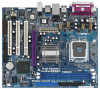
... (9.6 in) PARALLEL PORT Presler Conroe Dual Core CPU DDR2 (64/72 bit, 184-pin module) Dual Channel ConRoe865GV FSB800 DDR1 (64/72 bit, 184-pin module) USB 2.0 T: USB2 B: USB3 Top: RJ-45 USB... Audio Header (AUDIO1) 8 Primary IDE Connector (IDE1, Blue) 23 JR1 Jumper / JL1 Jumper 9 ASRock Graphics Interface Slot (1.5V_AGP1) 24 Internal Audio Connector: AUX1 (White) 10 South Bridge Controller 25 Internal ...ATA Connector (SATA2) 26 PCI Slots (PCI1- 3) 12 Primary Serial ATA Connector (SATA1) 27 BIOS FWH Chip 13 Chassis Fan Connector (CHA_FAN1) 28 Shared USB 2.0 Header (USB4_5, Blue) 14...
... (9.6 in) PARALLEL PORT Presler Conroe Dual Core CPU DDR2 (64/72 bit, 184-pin module) Dual Channel ConRoe865GV FSB800 DDR1 (64/72 bit, 184-pin module) USB 2.0 T: USB2 B: USB3 Top: RJ-45 USB... Audio Header (AUDIO1) 8 Primary IDE Connector (IDE1, Blue) 23 JR1 Jumper / JL1 Jumper 9 ASRock Graphics Interface Slot (1.5V_AGP1) 24 Internal Audio Connector: AUX1 (White) 10 South Bridge Controller 25 Internal ...ATA Connector (SATA2) 26 PCI Slots (PCI1- 3) 12 Primary Serial ATA Connector (SATA1) 27 BIOS FWH Chip 13 Chassis Fan Connector (CHA_FAN1) 28 Shared USB 2.0 Header (USB4_5, Blue) 14...

User Manual
Page 23
... your optical drive first. STEP 4: Connect the other end of the SATA data cable to [Auto], which means during overclocking, but PCI bus is in BIOS setup is necessary to connect a power supply with ATX 12V plug to the SATA hard disk. Please follow the order from up . 2.10 Serial ATA... cable to your system can provides sufficient power. Then, the drivers compatible to the motherboard's SATA connector. You may set "CPU Host Frequency" option of BIOS setup to the SATA hard disk. STEP 2: Connect the SATA power cable to this motherboard for internal storage devices.
... your optical drive first. STEP 4: Connect the other end of the SATA data cable to [Auto], which means during overclocking, but PCI bus is in BIOS setup is necessary to connect a power supply with ATX 12V plug to the SATA hard disk. Please follow the order from up . 2.10 Serial ATA... cable to your system can provides sufficient power. Then, the drivers compatible to the motherboard's SATA connector. You may set "CPU Host Frequency" option of BIOS setup to the SATA hard disk. STEP 2: Connect the SATA power cable to this motherboard for internal storage devices.

User Manual
Page 24
You may not exactly match what you see on your system. Please press during the Power-On-Self-Test (POST) to configure your screen. 3.1.1 BIOS Menu Bar The top of the screen has a menu bar with its test routines. If you start up the security features Exit To exit the ... is constantly being updated, the following selections: Main To set up the system time/date information Advanced To set up the advanced BIOS features H/W Monitor To display current hardware status Boot To set up the default system device to locate and load the Operating System Security To set ...
You may not exactly match what you see on your system. Please press during the Power-On-Self-Test (POST) to configure your screen. 3.1.1 BIOS Menu Bar The top of the screen has a menu bar with its test routines. If you start up the security features Exit To exit the ... is constantly being updated, the following selections: Main To set up the system time/date information Advanced To set up the advanced BIOS features H/W Monitor To display current hardware status Boot To set up the default system device to locate and load the Operating System Security To set ...

User Manual
Page 25
...the settings To save changes and exit the BIOS SETUP UTILITY To jump to the Exit Screen or exit the current screen 3.2 Main Screen When you enter the BIOS SETUP UTILITY, the Main screen will appear and display the system overview Main Advanced BIOS SETUP UTILITY H/W Monitor Boot System Overview ...System Time System Date [14:00:09] [Mon 07/24/2006] BIOS Version : ConRoe865GV BIOS P1.00 Processor Type : Intel (R) Pentium (R) CPU 3.20 GHz Processor Speed : 3200 MHz Cache Size : 1024KB Microcode Update : 0F34/17 Total Memory DIMM 1 DIMM 2...
...the settings To save changes and exit the BIOS SETUP UTILITY To jump to the Exit Screen or exit the current screen 3.2 Main Screen When you enter the BIOS SETUP UTILITY, the Main screen will appear and display the system overview Main Advanced BIOS SETUP UTILITY H/W Monitor Boot System Overview ...System Time System Date [14:00:09] [Mon 07/24/2006] BIOS Version : ConRoe865GV BIOS P1.00 Processor Type : Intel (R) Pentium (R) CPU 3.20 GHz Processor Speed : 3200 MHz Cache Size : 1024KB Microcode Update : 0F34/17 Total Memory DIMM 1 DIMM 2...

User Manual
Page 26
...Intel (R) SpeedStep(tm) tech. [Disabled] [Disabled] [Enabled] [Enabled] [Disabled] [Enabled] [Auto] Select how to malfunction. 3.3.1 CPU Configuration BIOS SETUP UTILITY Advanced CPU Configuration CPU Host Frequency Actual Frequency (MHz) Boot Failure Guard Spread Spectrum [Auto] [200] [Enabled] [Auto] Ratio Status ...Item Change Option General Help Load Defaults Save and Exit Exit v02.54 (C) Copyright 1985-2003, American Megatrends, Inc. BIOS SETUP UTILITY Main Advanced H/W Monitor Boot Security Exit Advanced Settings WARNING : Setting wrong values in below sections may cause ...
...Intel (R) SpeedStep(tm) tech. [Disabled] [Disabled] [Enabled] [Enabled] [Disabled] [Enabled] [Auto] Select how to malfunction. 3.3.1 CPU Configuration BIOS SETUP UTILITY Advanced CPU Configuration CPU Host Frequency Actual Frequency (MHz) Boot Failure Guard Spread Spectrum [Auto] [200] [Enabled] [Auto] Ratio Status ...Item Change Option General Help Load Defaults Save and Exit Exit v02.54 (C) Copyright 1985-2003, American Megatrends, Inc. BIOS SETUP UTILITY Main Advanced H/W Monitor Boot Security Exit Advanced Settings WARNING : Setting wrong values in below sections may cause ...

User Manual
Page 28
... Burst Length [4] Init. Hyper Threading Technology To enable this feature, it is set the "Power Schemes" as "Portable/Laptop" to enable this function. 3.3.2 Chipset Configuration BIOS SETUP UTILITY Advanced Chipset Configuration DRAM Frequency [Auto] Flexibility Option [Disabled] Configure DRAM Timing by SPD [Disabled] DRAM CAS# Latency [Auto] DRAM RAS# Precharge [4 Clocks...
... Burst Length [4] Init. Hyper Threading Technology To enable this feature, it is set the "Power Schemes" as "Portable/Laptop" to enable this function. 3.3.2 Chipset Configuration BIOS SETUP UTILITY Advanced Chipset Configuration DRAM Frequency [Auto] Flexibility Option [Disabled] Configure DRAM Timing by SPD [Disabled] DRAM CAS# Latency [Auto] DRAM RAS# Precharge [4 Clocks...

User Manual
Page 30
... On Use this item to enable or disable RTC (Real Time Clock) to set the power state after an unexpected AC/power loss. 3.3.3 ACPI Configuration BIOS SETUP UTILITY Advanced ACPI Configuration Suspend To RAM Restore on AC/Power Loss Use this item to enable or disable PCI devices to boot up...
... On Use this item to enable or disable RTC (Real Time Clock) to set the power state after an unexpected AC/power loss. 3.3.3 ACPI Configuration BIOS SETUP UTILITY Advanced ACPI Configuration Suspend To RAM Restore on AC/Power Loss Use this item to enable or disable PCI devices to boot up...

User Manual
Page 31
... also need to select between [Pri IDE + SATA] and [SATA + Sec IDE]. When [Enhanced Mode] is used . Configuration options: [Disabled], [Primary], [Secondary], [Both]. 3.3.4 IDE Configuration BIOS SETUP UTILITY Advanced IDE Configuration OnBoard IDE Operate Mode OnBoard IDE Controller Primary IDE Master Primary IDE Slave Secondary IDE Master Secondary IDE Slave SATA1...
... also need to select between [Pri IDE + SATA] and [SATA + Sec IDE]. When [Enhanced Mode] is used . Configuration options: [Disabled], [Primary], [Secondary], [Both]. 3.3.4 IDE Configuration BIOS SETUP UTILITY Advanced IDE Configuration OnBoard IDE Operate Mode OnBoard IDE Controller Primary IDE Master Primary IDE Slave Secondary IDE Master Secondary IDE Slave SATA1...

User Manual
Page 32
...ESC Select Screen Select Item Change Option General Help Load Defaults Save and Exit Exit v02.54 (C) Copyright 1985-2003, American Megatrends, Inc. BIOS SETUP UTILITY Advanced Primary IDE Master Device Vendor Size LBA Mode Block Mode PIO Mode Async DMA Ultra DMA S.M.A.R.T. LBA/Large Mode Use this item...to active. [CD/DVD]: This is used for IDE ARMD (ATAPI Removable Media Device), such as MO. After selecting the hard disk information into BIOS, use of device connected to disable the LBA/Large mode. 32 Type LBA/Large Mode Block (Multi-Sector Transfer) PIO Mode DMA Mode S.M.A.R.T. 32Bit...
...ESC Select Screen Select Item Change Option General Help Load Defaults Save and Exit Exit v02.54 (C) Copyright 1985-2003, American Megatrends, Inc. BIOS SETUP UTILITY Advanced Primary IDE Master Device Vendor Size LBA Mode Block Mode PIO Mode Async DMA Ultra DMA S.M.A.R.T. LBA/Large Mode Use this item...to active. [CD/DVD]: This is used for IDE ARMD (ATAPI Removable Media Device), such as MO. After selecting the hard disk information into BIOS, use of device connected to disable the LBA/Large mode. 32 Type LBA/Large Mode Block (Multi-Sector Transfer) PIO Mode DMA Mode S.M.A.R.T. 32Bit...

User Manual
Page 33
Configuration options: [Disabled], [Auto], [Enabled]. 32-Bit Data Transfer Use this item to maximize the IDE hard disk data transfer rate. 3.3.5 PCIPnP Configuration BIOS SETUP UTILITY Advanced PCI / PnP Configuration PCI Latency Timer PCI IDE BusMaster [32] [Enabled] Value in units of this feature is [Auto]. If this item ...
Configuration options: [Disabled], [Auto], [Enabled]. 32-Bit Data Transfer Use this item to maximize the IDE hard disk data transfer rate. 3.3.5 PCIPnP Configuration BIOS SETUP UTILITY Advanced PCI / PnP Configuration PCI Latency Timer PCI IDE BusMaster [32] [Enabled] Value in units of this feature is [Auto]. If this item ...

User Manual
Page 34
...General Help Load Defaults Save and Exit Exit v02.54 (C) Copyright 1985-2003, American Megatrends, Inc. 3.3.7 Super IO Configuration BIOS SETUP UTILITY Advanced Configure Super IO Chipset OnBoard Floppy Controller Serial Port Address Infrared Port Address Parallel Port Address Parallel Port Mode EPP...ECP Mode DMA Channel Parallel Port IRQ [Enabled] [3F8 / IRQ4] [Disabled] [378] [ECP + EPP] [1.9] [DMA3] [IRQ7] Allow BIOS to enable or disable floppy drive controller. 3.3.6 Floppy Configuration In this item to set the address for the onboard infrared port or disable it . ...
...General Help Load Defaults Save and Exit Exit v02.54 (C) Copyright 1985-2003, American Megatrends, Inc. 3.3.7 Super IO Configuration BIOS SETUP UTILITY Advanced Configure Super IO Chipset OnBoard Floppy Controller Serial Port Address Infrared Port Address Parallel Port Address Parallel Port Mode EPP...ECP Mode DMA Channel Parallel Port IRQ [Enabled] [3F8 / IRQ4] [Disabled] [378] [ECP + EPP] [1.9] [DMA3] [IRQ7] Allow BIOS to enable or disable floppy drive controller. 3.3.6 Floppy Configuration In this item to set the address for the onboard infrared port or disable it . ...

User Manual
Page 36
... emulate legacy I/O devices such as mouse, keyboard,... etc. Legacy USB Support Use this item to enable or disable the use of USB controller. 3.3.8 USB Configuration BIOS SETUP UTILITY Advanced USB Configuration USB Controller USB 2.0 Support Legacy USB Support [Enabled] [Enabled] [Disabled] To enable or disable the onboard USB controllers. +F1 F9...
... emulate legacy I/O devices such as mouse, keyboard,... etc. Legacy USB Support Use this item to enable or disable the use of USB controller. 3.3.8 USB Configuration BIOS SETUP UTILITY Advanced USB Configuration USB Controller USB 2.0 Support Legacy USB Support [Enabled] [Enabled] [Disabled] To enable or disable the onboard USB controllers. +F1 F9...

User Manual
Page 37
...], you will be within 2 C. The default value is [Disabled]. You can freely adjust the target fan speed according to identify the temperature of CPU fan. BIOS SETUP UTILITY Main Advanced H/W Monitor Boot Security Exit Hardware Health Event Monitoring CPU Temperature M / B Temperature : 45 C / 98 F : 31 C / 87 F CPU Fan Speed Chassis Fan Speed...
...], you will be within 2 C. The default value is [Disabled]. You can freely adjust the target fan speed according to identify the temperature of CPU fan. BIOS SETUP UTILITY Main Advanced H/W Monitor Boot Security Exit Hardware Health Event Monitoring CPU Temperature M / B Temperature : 45 C / 98 F : 31 C / 87 F CPU Fan Speed Chassis Fan Speed...

User Manual
Page 38
Main Advanced BIOS SETUP UTILITY H/W Monitor Boot Security Exit Boot Settings Boot Settings Configuration Boot Device Priority Hard Disk Drives Removable Drives CD / DVD Drives Configure Settings during ... Sub Screen F1 General Help F9 Load Defaults F10 Save and Exit ESC Exit v02.54 (C) Copyright 1985-2003, American Megatrends, Inc. 3.5.1 Boot Settings Configuration BIOS SETUP UTILITY Boot Boot Settings Configuration Boot From Network Bootup Num-Lock [Disabled] [On] To enable or disable the boot from network feature. +F1 F9...
Main Advanced BIOS SETUP UTILITY H/W Monitor Boot Security Exit Boot Settings Boot Settings Configuration Boot Device Priority Hard Disk Drives Removable Drives CD / DVD Drives Configure Settings during ... Sub Screen F1 General Help F9 Load Defaults F10 Save and Exit ESC Exit v02.54 (C) Copyright 1985-2003, American Megatrends, Inc. 3.5.1 Boot Settings Configuration BIOS SETUP UTILITY Boot Boot Settings Configuration Boot From Network Bootup Num-Lock [Disabled] [On] To enable or disable the boot from network feature. +F1 F9...

User Manual
Page 39
BIOS SETUP UTILITY Main Advanced H/W Monitor Boot Security Exit Security Settings Supervisor Password : Not Installed User Password : Not Installed Change Supervisor Password Change User Password Clear ... Select Item Enter Change F1 General Help F9 Load Defaults F10 Save and Exit ESC Exit v02.54 (C) Copyright 1985-2003, American Megatrends, Inc. 39 BIOS SETUP UTILITY Boot Boot Device Priority 1st Boot Device 2nd Boot Device 3rd Boot Device [1st FLOPPY DRIVE] [HDD: PM-MAXTOR 6L08] [CD / DVD] Specifies...
BIOS SETUP UTILITY Main Advanced H/W Monitor Boot Security Exit Security Settings Supervisor Password : Not Installed User Password : Not Installed Change Supervisor Password Change User Password Clear ... Select Item Enter Change F1 General Help F9 Load Defaults F10 Save and Exit ESC Exit v02.54 (C) Copyright 1985-2003, American Megatrends, Inc. 39 BIOS SETUP UTILITY Boot Boot Device Priority 1st Boot Device 2nd Boot Device 3rd Boot Device [1st FLOPPY DRIVE] [HDD: PM-MAXTOR 6L08] [CD / DVD] Specifies...

User Manual
Page 40
... select this option, it will pop-out the following message, "Load optimal defaults?" Select [OK] to save the changes and exit the BIOS SETUP UTILITY. Load Optimal Defaults When you select this option, it will pop-out the following message, "Discard changes?" Select [OK] to... Exit When you select this option, it will pop-out the following message, "Discard changes and exit setup?" 3.7 Exit Screen Main BIOS SETUP UTILITY Advanced H/W Monitro Boot Security Exit Exit Options Save Changes and Exit Discard Changes and Exit Discard Changes Load Optimal Defaults Exit ...
... select this option, it will pop-out the following message, "Load optimal defaults?" Select [OK] to save the changes and exit the BIOS SETUP UTILITY. Load Optimal Defaults When you select this option, it will pop-out the following message, "Discard changes?" Select [OK] to... Exit When you select this option, it will pop-out the following message, "Discard changes and exit setup?" 3.7 Exit Screen Main BIOS SETUP UTILITY Advanced H/W Monitro Boot Security Exit Exit Options Save Changes and Exit Discard Changes and Exit Discard Changes Load Optimal Defaults Exit ...

Quick Installation Guide
Page 2
...Connector (IDE2, Black) 22 Front Panel Audio Header (AUDIO1) 8 Primary IDE Connector (IDE1, Blue) 23 JR1 Jumper / JL1 Jumper 9 ASRock Graphics Interface Slot (1.5V_AGP1) 24 Internal Audio Connector: AUX1 (White) 10 South Bridge Controller 25 Internal Audio Connector: CD1 (Black) 11 Secondary...) 26 PCI Slots (PCI1- 3) 12 Primary Serial ATA Connector (SATA1) 27 BIOS FWH Chip 13 Chassis Fan Connector (CHA_FAN1) 28 Shared USB 2.0 Header (USB4_5, Blue) 14 System Panel Header (PANEL1) 29 ATX 12V Connector (ATX12V1) 15 Chassis Speaker Header (SPEAKER 1) 2 ASRock ConRoe865GV Motherboard
...Connector (IDE2, Black) 22 Front Panel Audio Header (AUDIO1) 8 Primary IDE Connector (IDE1, Blue) 23 JR1 Jumper / JL1 Jumper 9 ASRock Graphics Interface Slot (1.5V_AGP1) 24 Internal Audio Connector: AUX1 (White) 10 South Bridge Controller 25 Internal Audio Connector: CD1 (Black) 11 Secondary...) 26 PCI Slots (PCI1- 3) 12 Primary Serial ATA Connector (SATA1) 27 BIOS FWH Chip 13 Chassis Fan Connector (CHA_FAN1) 28 Shared USB 2.0 Header (USB4_5, Blue) 14 System Panel Header (PANEL1) 29 ATX 12V Connector (ATX12V1) 15 Chassis Speaker Header (SPEAKER 1) 2 ASRock ConRoe865GV Motherboard


