User Manual
Page 2
...may cause undesired operation. In no responsibility for backup purpose, without notice, and should not be constructed as a commitment by ASRock. When you discard the Lithium battery in California, USA, please follow the related regulations in Perchlorate Best Management Practices (BMP)...without written consent of ASRock Inc. With respect to the contents of this manual, ASRock does not provide warranty of any interference received, including interference that may appear in this manual. CALIFORNIA, USA ONLY The Lithium battery adopted on this motherboard contains Perchlorate, a ...
...may cause undesired operation. In no responsibility for backup purpose, without notice, and should not be constructed as a commitment by ASRock. When you discard the Lithium battery in California, USA, please follow the related regulations in Perchlorate Best Management Practices (BMP)...without written consent of ASRock Inc. With respect to the contents of this manual, ASRock does not provide warranty of any interference received, including interference that may appear in this manual. CALIFORNIA, USA ONLY The Lithium battery adopted on this motherboard contains Perchlorate, a ...
User Manual
Page 3
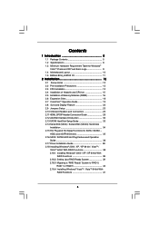
Contents 1 Introduction 5 1.1 Package Contents 5 1.2 Specifications 6 1.3 Minimum Hardware Requirement Table for Windows® VistaTM Premium 2007 and Basic Logo 9 1.4 Motherboard Layout 10 1.5 ASRock 8CH_eSATAII I/O 11 2 Installation 12 2.1 Screw Holes 12 2.2 Pre-installation Precautions 12 2.3 CPU Installation 13 2.4 Installation of Heatsink and CPU fan 15 2.5 Installation of Memory Modules (...
Contents 1 Introduction 5 1.1 Package Contents 5 1.2 Specifications 6 1.3 Minimum Hardware Requirement Table for Windows® VistaTM Premium 2007 and Basic Logo 9 1.4 Motherboard Layout 10 1.5 ASRock 8CH_eSATAII I/O 11 2 Installation 12 2.1 Screw Holes 12 2.2 Pre-installation Precautions 12 2.3 CPU Installation 13 2.4 Installation of Heatsink and CPU fan 15 2.5 Installation of Memory Modules (...
User Manual
Page 5
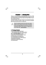
... you for a 3.5-in , 30.5 cm x 21.8 cm) ASRock ConRoe1333-eSATA2 Quick Installation Guide ASRock ConRoe1333-eSATA2 Support CD One 80-conductor Ultra ATA 66/100 IDE Ribbon Cable One Ribbon Cable for purchasing ASRock ConRoe1333-eSATA2 motherboard, a reliable motherboard produced under ASRock's consistently stringent quality control. It delivers excellent performance with robust design conforming to ASRock's commitment to BIOS setup and information of...
... you for a 3.5-in , 30.5 cm x 21.8 cm) ASRock ConRoe1333-eSATA2 Quick Installation Guide ASRock ConRoe1333-eSATA2 Support CD One 80-conductor Ultra ATA 66/100 IDE Ribbon Cable One Ribbon Cable for purchasing ASRock ConRoe1333-eSATA2 motherboard, a reliable motherboard produced under ASRock's consistently stringent quality control. It delivers excellent performance with robust design conforming to ASRock's commitment to BIOS setup and information of...
User Manual
Page 8
... spray thermal grease between the CPU and the heatsink when you resume the system, please check if the CPU fan on the motherboard functions properly and unplug the power cord, then plug it will operate in the BIOS, applying Untied Overclocking Technology, or using the... modules on page 16 for proper connection. 8 Overclocking may cause the instability of "Hyper Threading Technology", please check page 48. 3. This motherboard supports Untied Overclocking Technology. Please check the table below for possible damage caused by overclocking. dows® XP, Windows® XP 64-bit...
... spray thermal grease between the CPU and the heatsink when you resume the system, please check if the CPU fan on the motherboard functions properly and unplug the power cord, then plug it will operate in the BIOS, applying Untied Overclocking Technology, or using the... modules on page 16 for proper connection. 8 Overclocking may cause the instability of "Hyper Threading Technology", please check page 48. 3. This motherboard supports Untied Overclocking Technology. Please check the table below for possible damage caused by overclocking. dows® XP, Windows® XP 64-bit...
User Manual
Page 9
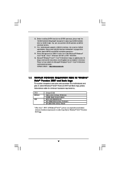
ASRock website http://www.asrock.com 1.3 Minimum Hardware Requirement Table for Windows® VistaTM Premium 2007 and Basic Logo For system integrators and users who purchase this motherboard and plan to submit Windows® VistaTM Premium 2007 and Basic logo, please follow below table for details ...fine under Microsoft® Windows® VistaTM 64-bit / VistaTM / XP 64-bit / XP SP1 or SP2 / 2000 SP4. 13. This motherboard supports eSATAII interface, the external SATAII specification. CPU Memory VGA Celeron D 326 1GB system memory (Premium) 512MB Single Channel (Basic) DX9.0 with...
ASRock website http://www.asrock.com 1.3 Minimum Hardware Requirement Table for Windows® VistaTM Premium 2007 and Basic Logo For system integrators and users who purchase this motherboard and plan to submit Windows® VistaTM Premium 2007 and Basic logo, please follow below table for details ...fine under Microsoft® Windows® VistaTM 64-bit / VistaTM / XP 64-bit / XP SP1 or SP2 / 2000 SP4. 13. This motherboard supports eSATAII interface, the external SATAII specification. CPU Memory VGA Celeron D 326 1GB system memory (Premium) 512MB Single Channel (Basic) DX9.0 with...
User Manual
Page 12
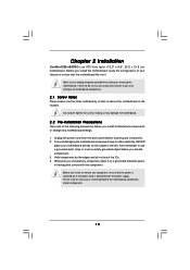
.../or components. 12 Unplug the power cord from the power supply. Hold components by circles to secure the motherboard to unplug the power cord before you install or remove any component. 2. Chapter 2 Installation ConRoe1333-eSATA2 is detached from the wall socket before you handle components. 3. Failure to use a grounded wrist strap or touch...
.../or components. 12 Unplug the power cord from the power supply. Hold components by circles to secure the motherboard to unplug the power cord before you install or remove any component. 2. Chapter 2 Installation ConRoe1333-eSATA2 is detached from the wall socket before you handle components. 3. Failure to use a grounded wrist strap or touch...
User Manual
Page 14
... 4. Close the socket: Step 4-1. Step 4-2. Carefully place the CPU into the socket by using a purely vertical motion. This cap must be placed if returning the motherboard for after service. Secure load lever with right hand thumb and peel the cap from the socket while pressing on load plate, engage the load...
... 4. Close the socket: Step 4-1. Step 4-2. Carefully place the CPU into the socket by using a purely vertical motion. This cap must be placed if returning the motherboard for after service. Secure load lever with right hand thumb and peel the cap from the socket while pressing on load plate, engage the load...
User Manual
Page 15
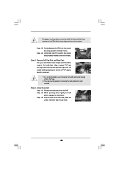
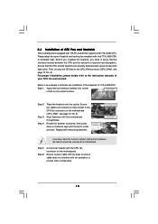
... the fastener clockwise, then press down the fasteners without rotating them clockwise, the heatsink cannot be secured on fastener caps with the motherboard throughholes. If you need to spray thermal interface material between the CPU and the heatsink to dissipate heat. Ensure that supports Intel 775...manuals of heatsink and cooling fan compliant with fan operation or contact other . Step 3. Repeat with the CPU fan connector on the motherboard. Connect fan header with remaining fasteners. Then connect the CPU fan to install and lock. Align fasteners with thumb to the CPU_FAN ...
... the fastener clockwise, then press down the fasteners without rotating them clockwise, the heatsink cannot be secured on fastener caps with the motherboard throughholes. If you need to spray thermal interface material between the CPU and the heatsink to dissipate heat. Ensure that supports Intel 775...manuals of heatsink and cooling fan compliant with fan operation or contact other . Step 3. Repeat with the CPU fan connector on the motherboard. Connect fan header with remaining fasteners. Then connect the CPU fan to install and lock. Align fasteners with thumb to the CPU_FAN ...
User Manual
Page 16
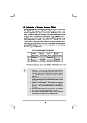
...Populated Populated Populated Populated * For the configuration (3), please install identical DDRII DIMMs in Dual Channel B (DDRII_2 and DDRII_4; otherwise, this motherboard, it is NOT installed in the same Dual Channel, for dual channel configuration, and please install identical DDRII DIMMs in all four slots... Technology . 4. In other words, install them in the slots of memory modules in the slots of Memory Modules (DIMM) ConRoe1333-eSATA2 motherboard provides four 240-pin DDRII (Double Data Rate II) DIMM slots, and supports Dual Channel Memory Technology. In other words, ...
...Populated Populated Populated Populated * For the configuration (3), please install identical DDRII DIMMs in Dual Channel B (DDRII_2 and DDRII_4; otherwise, this motherboard, it is NOT installed in the same Dual Channel, for dual channel configuration, and please install identical DDRII DIMMs in all four slots... Technology . 4. In other words, install them in the slots of memory modules in the slots of Memory Modules (DIMM) ConRoe1333-eSATA2 motherboard provides four 240-pin DDRII (Double Data Rate II) DIMM slots, and supports Dual Channel Memory Technology. In other words, ...
User Manual
Page 17
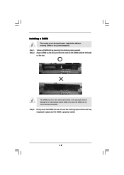
Unlock a DIMM slot by pressing the retaining clips outward. Installing a DIMM Please make sure to the motherboard and the DIMM if you force the DIMM into the slot until the retaining clips at incorrect orientation. Step 1. Step 2. notch break notch break The ...
Unlock a DIMM slot by pressing the retaining clips outward. Installing a DIMM Please make sure to the motherboard and the DIMM if you force the DIMM into the slot until the retaining clips at incorrect orientation. Step 1. Step 2. notch break notch break The ...
User Manual
Page 18
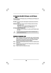
... cards that have the 32-bit PCI interface. PCIE2 (PCIE x1 slot) is used to install only one PCI Express card on this motherboard, please install it on this motherboard. AGI Express slot (PCI Express x4): AGI Express slot (PCI Express x4) is used for PCI Express cards with screws. 18 If...
... cards that have the 32-bit PCI interface. PCIE2 (PCIE x1 slot) is used to install only one PCI Express card on this motherboard, please install it on this motherboard. AGI Express slot (PCI Express x4): AGI Express slot (PCI Express x4) is used for PCI Express cards with screws. 18 If...
User Manual
Page 19
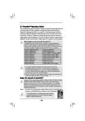
...series, or two CrossFireTM Ready cards if they will operate as the example graphics card. 2.7 CrossFireTM Operation Guide This motherboard supports CrossFireTM feature. This applies to ATITM graphics card manuals for detailed installation guide. For other CrossFireTM cards that ATITM... refer to cards from ATITM or any 3D application. All three CrossFireTM components, a CrossFireTM Ready graphics card, a CrossFireTM Ready motherboard and a CrossFireTM Edition co-processor graphics card, must be installed correctly to perform the benefit of its partners. Combining a range...
...series, or two CrossFireTM Ready cards if they will operate as the example graphics card. 2.7 CrossFireTM Operation Guide This motherboard supports CrossFireTM feature. This applies to ATITM graphics card manuals for detailed installation guide. For other CrossFireTM cards that ATITM... refer to cards from ATITM or any 3D application. All three CrossFireTM components, a CrossFireTM Ready graphics card, a CrossFireTM Ready motherboard and a CrossFireTM Edition co-processor graphics card, must be installed correctly to perform the benefit of its partners. Combining a range...
User Manual
Page 20
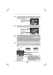
..., there are allowed to install two CrossFireTM Edition graphics cards to both slots, or you install two standard Radeon (CrossFireTM Ready) graphics cards to this motherboard, please skip this step.) DVI-DMS cable Connect the DVI-DMS cable to support CrossFireTM. Step 2. Standard Radeon (CrossFireTM Ready) graphics card Step 3. Install the...
..., there are allowed to install two CrossFireTM Edition graphics cards to both slots, or you install two standard Radeon (CrossFireTM Ready) graphics cards to this motherboard, please skip this step.) DVI-DMS cable Connect the DVI-DMS cable to support CrossFireTM. Step 2. Standard Radeon (CrossFireTM Ready) graphics card Step 3. Install the...
User Manual
Page 21
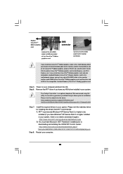
...to the monitor connector. If you install one CrossFireTM Edition graphics card and one compatible standard Radeon (CrossFireTM Ready) graphics card to this motherboard, please connect one end of DVI-DMS cable to the monitor, another end to DMS of one end of the CrossFireTM Edition graphics...and installing the CATALYST Control Center: http://www.microsoft.com/downloads/details.aspx? If you install two CrossFireTM Edition graphics cards to this motherboard, please connect one of the CrossFireTM Edition graphics cards to PCIE1 slot, and the other end to download it again): http://www....
...to the monitor connector. If you install one CrossFireTM Edition graphics card and one compatible standard Radeon (CrossFireTM Ready) graphics card to this motherboard, please connect one end of DVI-DMS cable to the monitor, another end to DMS of one end of the CrossFireTM Edition graphics...and installing the CATALYST Control Center: http://www.microsoft.com/downloads/details.aspx? If you install two CrossFireTM Edition graphics cards to this motherboard, please connect one of the CrossFireTM Edition graphics cards to PCIE1 slot, and the other end to download it again): http://www....
User Manual
Page 22
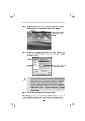
... selected or not; Then you are able to infringe. 22 You will automatically reboot. Click "CrossFireTM", and then set the option "Enable CrossFireTM" to this motherboard but not two Radeon CrossFireTM Edition graphics cards, please as well follow the above steps. if not, please select it again, and then you will...
... selected or not; Then you are able to infringe. 22 You will automatically reboot. Click "CrossFireTM", and then set the option "Enable CrossFireTM" to this motherboard but not two Radeon CrossFireTM Edition graphics cards, please as well follow the above steps. if not, please select it again, and then you will...
User Manual
Page 23
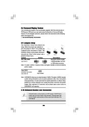
2.8 Surround Display Feature This motherboard supports Surround Display upgrade. For the detailed instruction, please refer to the document at the following path in the Support CD: ..\ Surround Display Information 2.9 Jumpers ... wake up events. Jumper Setting Description PS2_USB_PWR1 1_2 (see p.10 No. 10) 2-pin jumper Note: CLRCMOS1 allows you can easily enjoy the benefits of the motherboard! 23 With the external add-on PCI Express VGA card, you to default setup, please turn off the computer and unplug the power cord from...
2.8 Surround Display Feature This motherboard supports Surround Display upgrade. For the detailed instruction, please refer to the document at the following path in the Support CD: ..\ Surround Display Information 2.9 Jumpers ... wake up events. Jumper Setting Description PS2_USB_PWR1 1_2 (see p.10 No. 10) 2-pin jumper Note: CLRCMOS1 allows you can easily enjoy the benefits of the motherboard! 23 With the external add-on PCI Express VGA card, you to default setup, please turn off the computer and unplug the power cord from...
User Manual
Page 24
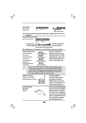
...24 Primary IDE connector (Blue) (39-pin IDE1, see p.10 No. 16) PIN1 IDE1 connect the blue end connect the black end to the motherboard to the IDE devices 80-conductor ATA 66/100 cable Note: Please refer to the SATA / SATAII hard disk or the SATAII connector on page... 30 for the details. Please read "eSATAII Interface Introduction" on the motherboard. The current eSATA II interface allows up to 3.0 Gb/s data transfer rate. Serial ATA II Connectors (SATAII_BLUE (PORT0): see p.10, No. 19) (SATAII_BLACK (...
...24 Primary IDE connector (Blue) (39-pin IDE1, see p.10 No. 16) PIN1 IDE1 connect the blue end connect the black end to the motherboard to the IDE devices 80-conductor ATA 66/100 cable Note: Please refer to the SATA / SATAII hard disk or the SATAII connector on page... 30 for the details. Please read "eSATAII Interface Introduction" on the motherboard. The current eSATA II interface allows up to 3.0 Gb/s data transfer rate. Serial ATA II Connectors (SATAII_BLUE (PORT0): see p.10, No. 19) (SATAII_BLACK (...
User Manual
Page 25
... sound sources such as a CD-ROM, DVD-ROM, TV tuner card, or MPEG card. 25 This connector allows you to the power connector on this motherboard. USB 2.0 Headers (9-pin USB67) (see p.10 No. 28) CD-L GND GND CD-R CD1 This header supports an optional wireless transmitting and receiving infrared module...
... sound sources such as a CD-ROM, DVD-ROM, TV tuner card, or MPEG card. 25 This connector allows you to the power connector on this motherboard. USB 2.0 Headers (9-pin USB67) (see p.10 No. 28) CD-L GND GND CD-R CD1 This header supports an optional wireless transmitting and receiving infrared module...
User Manual
Page 27
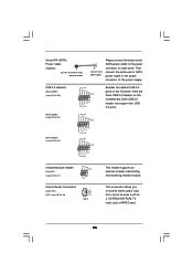
...SLI/XFIRE_POWER1) (see p.10 No. 2) Please connect an ATX 12V power supply to this connector. There are plugged to this connector. Though this motherboard provides 4-Pin CPU fan (Quiet Fan) support, the 3-Pin CPU fan still can support one back panel IEEE 1394 header (BACK_1394). Game Port ... a hard disk power connecor when two graphics cards are two IEEE 1394 headers on this connector, but please connect it to use this motherboard, including one front panel IEEE 1394 header (FRONT_1394) and one IEEE 1394 port. 27 Pin 1-3 Connected 3-Pin Fan Installation ATX Power Connector...
...SLI/XFIRE_POWER1) (see p.10 No. 2) Please connect an ATX 12V power supply to this connector. There are plugged to this connector. Though this motherboard provides 4-Pin CPU fan (Quiet Fan) support, the 3-Pin CPU fan still can support one back panel IEEE 1394 header (BACK_1394). Game Port ... a hard disk power connecor when two graphics cards are two IEEE 1394 headers on this connector, but please connect it to use this motherboard, including one front panel IEEE 1394 header (FRONT_1394) and one IEEE 1394 port. 27 Pin 1-3 Connected 3-Pin Fan Installation ATX Power Connector...
User Manual
Page 28
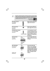
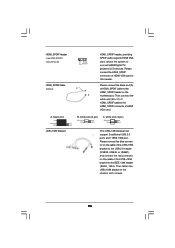
... blue connector on the cable of this USB+1394 bracket to the USB 2.0 header (USB23, USB45, or USB67), and connect the red connector on the motherboard. HDMI_SPDIF Header (3-pin HDMI_SPDIF1) (see p.10 No. 30) 1 GND SPDIFOUT +5V HDMI_SPDIF Cable (Optional) C B A HDMI_SPDIF header, providing SPDIF audio output to HDMI VGA card, allows...
... blue connector on the cable of this USB+1394 bracket to the USB 2.0 header (USB23, USB45, or USB67), and connect the red connector on the motherboard. HDMI_SPDIF Header (3-pin HDMI_SPDIF1) (see p.10 No. 30) 1 GND SPDIFOUT +5V HDMI_SPDIF Cable (Optional) C B A HDMI_SPDIF header, providing SPDIF audio output to HDMI VGA card, allows...

