User Manual
Page 2
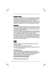
... (BMP) regulations passed by the California Legislature. With respect to the contents of this manual, ASRock does not provide warranty of any defect or error in advance. CALIFORNIA, USA ONLY The Lithium battery adopted on this motherboard contains Perchlorate, a toxic substance controlled in this manual may or may not be registered trademarks...
... (BMP) regulations passed by the California Legislature. With respect to the contents of this manual, ASRock does not provide warranty of any defect or error in advance. CALIFORNIA, USA ONLY The Lithium battery adopted on this motherboard contains Perchlorate, a toxic substance controlled in this manual may or may not be registered trademarks...

User Manual
Page 3
... 5 1.1 Package Contents 5 1.2 Specifications 6 1.3 Minimum Hardware Requirement Table for Windows® VistaTM Premium 2007 and Basic Logo 9 1.4 Motherboard Layout 10 1.5 HD 8CH I/O 11 2 Installation 12 2.1 Screw Holes 12 2.2 Pre-installation Precautions 12 2.3 CPU Installation 13 2.4 Installation...and CPU fan 15 2.5 Installation of Memory Modules (DIMM 16 2.6 Expansion Slots (PCI, HDMR, and PCI Express Slots) ....... 18 2.7 DVI Graphics-HDCP Card Installation Guide 19 2.8 Jumpers Setup 21 2.9 Onboard Headers and Connectors 22 2.10 SATAII Hard Disk Setup Guide 26 2.11 Serial...
... 5 1.1 Package Contents 5 1.2 Specifications 6 1.3 Minimum Hardware Requirement Table for Windows® VistaTM Premium 2007 and Basic Logo 9 1.4 Motherboard Layout 10 1.5 HD 8CH I/O 11 2 Installation 12 2.1 Screw Holes 12 2.2 Pre-installation Precautions 12 2.3 CPU Installation 13 2.4 Installation...and CPU fan 15 2.5 Installation of Memory Modules (DIMM 16 2.6 Expansion Slots (PCI, HDMR, and PCI Express Slots) ....... 18 2.7 DVI Graphics-HDCP Card Installation Guide 19 2.8 Jumpers Setup 21 2.9 Onboard Headers and Connectors 22 2.10 SATAII Hard Disk Setup Guide 26 2.11 Serial...

User Manual
Page 5
... contain the configuration guide to BIOS setup and information of the motherboard and step-bystep guide to the hardware installation. ASRock website http://www.asrock.com 1.1 Package Contents ASRock ConRoe1333-DVI/H Motherboard (Micro ATX Form Factor: 9.6-in x 9.6-in Floppy Drive One...24.4 cm x 24.4 cm) ASRock ConRoe1333-DVI/H Quick Installation Guide ASRock ConRoe1333-DVI/H Support CD One 80-conductor Ultra ATA 66/100 IDE Ribbon Cable One Ribbon Cable for purchasing ASRock ConRoe1333-DVI/H motherboard, a reliable motherboard produced under ASRock's consistently stringent quality control. In ...
... contain the configuration guide to BIOS setup and information of the motherboard and step-bystep guide to the hardware installation. ASRock website http://www.asrock.com 1.1 Package Contents ASRock ConRoe1333-DVI/H Motherboard (Micro ATX Form Factor: 9.6-in x 9.6-in Floppy Drive One...24.4 cm x 24.4 cm) ASRock ConRoe1333-DVI/H Quick Installation Guide ASRock ConRoe1333-DVI/H Support CD One 80-conductor Ultra ATA 66/100 IDE Ribbon Cable One Ribbon Cable for purchasing ASRock ConRoe1333-DVI/H motherboard, a reliable motherboard produced under ASRock's consistently stringent quality control. In ...
User Manual
Page 8
...SATAII mode. Microsoft® Windows® VistaTM / VistaTM 64-bit driver keeps on page 11 for details. 4. ASRock website http://www.asrock.com 8 This motherboard supports Untied Overclocking Technology. Before you install the PC system. 9. Please check the table below for Microsoft® Windows... to our website in overclocking mode. Please check the table on updating now. sponding memory support frequency. Although this motherboard offers stepless control, it to perform over-clocking. You can also connect SATA hard disk to spray thermal grease between...
...SATAII mode. Microsoft® Windows® VistaTM / VistaTM 64-bit driver keeps on page 11 for details. 4. ASRock website http://www.asrock.com 8 This motherboard supports Untied Overclocking Technology. Before you install the PC system. 9. Please check the table below for Microsoft® Windows... to our website in overclocking mode. Please check the table on updating now. sponding memory support frequency. Although this motherboard offers stepless control, it to perform over-clocking. You can also connect SATA hard disk to spray thermal grease between...
User Manual
Page 9
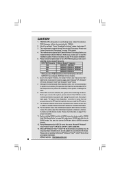
..., please adjust the shared memory size of onboard VGA can be adjusted up to 128MB. * If you use external graphics card on this motherboard and plan to submit Windows® VistaTM Premium 2007 and Basic logo, please follow below table for Windows® VistaTM Premium 2007 logo. ... Windows® VistaTM Premium 2007 and Basic Logo For system integrators and users who purchase this motherboard, please refer to Premium Discrete requirement at http://www.asrock.com * If the onboard VGA supports DVI, it must also support HDCP function to qualify for Windows® VistaTM Premium 2007 logo. ...
..., please adjust the shared memory size of onboard VGA can be adjusted up to 128MB. * If you use external graphics card on this motherboard and plan to submit Windows® VistaTM Premium 2007 and Basic logo, please follow below table for Windows® VistaTM Premium 2007 logo. ... Windows® VistaTM Premium 2007 and Basic Logo For system integrators and users who purchase this motherboard, please refer to Premium Discrete requirement at http://www.asrock.com * If the onboard VGA supports DVI, it must also support HDCP function to qualify for Windows® VistaTM Premium 2007 logo. ...

User Manual
Page 10
... ATX 12V Connector (ATX12V1) 16 Primary SATAII Connector (SATAII_1; Orange) 29 Serial Port Connector (COM1) 14 Secondary SATAII Connector (SATAII_2; 1.4 Motherboard Layout 1 23 PS2 Mouse 1 PS2_USB_PWR1 CPU_FAN1 PS2 Keyboard ATX12V1 4 24.4cm (9.6 in) 5 67 8 CLRCMOS1 CMOS Battery PARALLEL PORT DDRII_4 ...USB4_5 IDE1 1 USB6_7 SATAII_3 SATAII_1 USB2.0 CHA_FAN1 SATAII_4 SATAII_2 SPEAKER1 1 PANEL 1 PLED PWRBTN 1 HDLED RESET Dual Core CPU Dual Channel ConRoe1333-DVI/H 22 21 20 19 18 17 161514 13 DDRII667 24.4cm (9.6 in) 9 10 11 12 1 PS2_USB_PWR1 Jumper 15 Third SATAII ...
... ATX 12V Connector (ATX12V1) 16 Primary SATAII Connector (SATAII_1; Orange) 29 Serial Port Connector (COM1) 14 Secondary SATAII Connector (SATAII_2; 1.4 Motherboard Layout 1 23 PS2 Mouse 1 PS2_USB_PWR1 CPU_FAN1 PS2 Keyboard ATX12V1 4 24.4cm (9.6 in) 5 67 8 CLRCMOS1 CMOS Battery PARALLEL PORT DDRII_4 ...USB4_5 IDE1 1 USB6_7 SATAII_3 SATAII_1 USB2.0 CHA_FAN1 SATAII_4 SATAII_2 SPEAKER1 1 PANEL 1 PLED PWRBTN 1 HDLED RESET Dual Core CPU Dual Channel ConRoe1333-DVI/H 22 21 20 19 18 17 161514 13 DDRII667 24.4cm (9.6 in) 9 10 11 12 1 PS2_USB_PWR1 Jumper 15 Third SATAII ...

User Manual
Page 12
... any component. 2. Hold components by circles to secure the motherboard to you install motherboard components or change any motherboard settings. 1. Whenever you install the motherboard, study the configuration of the following precautions before you and damages to the motherboard, peripherals, and/or components. 12 Chapter 2 Installation ConRoe1333-DVI/H is detached from the wall socket before installing or...
... any component. 2. Hold components by circles to secure the motherboard to you install motherboard components or change any motherboard settings. 1. Whenever you install the motherboard, study the configuration of the following precautions before you and damages to the motherboard, peripherals, and/or components. 12 Chapter 2 Installation ConRoe1333-DVI/H is detached from the wall socket before installing or...
User Manual
Page 14
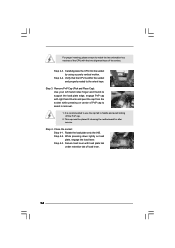
Step 3. It is within the socket and properly mated to the orient keys. Step 2-3. This cap must be placed if returning the motherboard for after service. Step 4-2. Verify that the CPU is recommended to use the cap tab to handle and avoid kicking off the PnP cap. 2. Step 4-3. ...
Step 3. It is within the socket and properly mated to the orient keys. Step 2-3. This cap must be placed if returning the motherboard for after service. Step 4-2. Verify that the CPU is recommended to use the cap tab to handle and avoid kicking off the PnP cap. 2. Step 4-3. ...
User Manual
Page 15
... Step 5. Step 4. Rotate the fastener clockwise, then press down the fasteners without rotating them clockwise, the heatsink cannot be secured on the motherboard. If you need to spray thermal interface material between the CPU and the heatsink to improve heat dissipation. 2.4 Installation of CPU Fan and ...Heatsink This motherboard is an example to illustrate the installation of the heatsink for 775-LAND CPU. Please adopt the type of heatsink and cooling fan...
... Step 5. Step 4. Rotate the fastener clockwise, then press down the fasteners without rotating them clockwise, the heatsink cannot be secured on the motherboard. If you need to spray thermal interface material between the CPU and the heatsink to improve heat dissipation. 2.4 Installation of CPU Fan and ...Heatsink This motherboard is an example to illustrate the installation of the heatsink for 775-LAND CPU. Please adopt the type of heatsink and cooling fan...

User Manual
Page 16
...a DDR memory module into DDRII slot; If a pair of the same color. otherwise, this motherboard, it is not allowed to activate the Dual Channel Memory Technology. 3. This motherboard also allows you have to activate the Dual Channel Memory Technology . 4. Dual Channel Memory Configurations...in DDRII_1 and DDRII_2, it is recommended to install two memory modules, for example, installing a pair of Memory Modules (DIMM) ConRoe1333-DVI/H motherboard provides four 240-pin DDRII (Double Data Rate II) DIMM slots, and supports Dual Channel Memory Technology. 2.5 Installation of memory ...
...a DDR memory module into DDRII slot; If a pair of the same color. otherwise, this motherboard, it is not allowed to activate the Dual Channel Memory Technology. 3. This motherboard also allows you have to activate the Dual Channel Memory Technology . 4. Dual Channel Memory Configurations...in DDRII_1 and DDRII_2, it is recommended to install two memory modules, for example, installing a pair of Memory Modules (DIMM) ConRoe1333-DVI/H motherboard provides four 240-pin DDRII (Double Data Rate II) DIMM slots, and supports Dual Channel Memory Technology. 2.5 Installation of memory ...
User Manual
Page 17
Installing a DIMM Please make sure to the motherboard and the DIMM if you force the DIMM into the slot until the retaining clips at incorrect orientation. Step 2. It will cause permanent damage to ...
Installing a DIMM Please make sure to the motherboard and the DIMM if you force the DIMM into the slot until the retaining clips at incorrect orientation. Step 2. It will cause permanent damage to ...

User Manual
Page 18
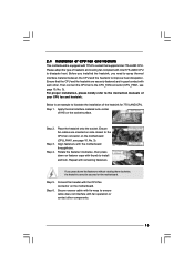
... install to the chassis with the slot and press firmly until the card is used for the card before you install the add-on this motherboard. Installing an expansion card Step 1. Align the card connector with screws. 18 If you intend to PCIE1 (PCIE x16 slot), the onboard VGA will ... sure that the power supply is switched off or the power cord is used to insert a HDMR card with x16 lane width graphics cards or ASRock DVI Graphics-HDCP card. Step 2. 2.6 Expansion Slots (PCI, HDMR and PCI Express Slots) There are used to install expansion cards that have the 32-bit PCI...
... install to the chassis with the slot and press firmly until the card is used for the card before you install the add-on this motherboard. Installing an expansion card Step 1. Align the card connector with screws. 18 If you intend to PCIE1 (PCIE x16 slot), the onboard VGA will ... sure that the power supply is switched off or the power cord is used to insert a HDMR card with x16 lane width graphics cards or ASRock DVI Graphics-HDCP card. Step 2. 2.6 Expansion Slots (PCI, HDMR and PCI Express Slots) There are used to install expansion cards that have the 32-bit PCI...
User Manual
Page 19
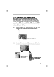
... expansion card installation procedures on this motherboard. Please refer to PCIE1 (PCIE x16 slot) on page 18 for proper installation of DVI Graphics-HDCP card. DVI-D connector of DVI-D monitor DVI-D output connector of DVI GraphicsHDCP card which is inserted to the DVI-D output connector of DVI Graphics-HDCP card 19 Step 1. 2.7 DVI Graphics-HDCP Card Installation Guide With...
... expansion card installation procedures on this motherboard. Please refer to PCIE1 (PCIE x16 slot) on page 18 for proper installation of DVI Graphics-HDCP card. DVI-D connector of DVI-D monitor DVI-D output connector of DVI GraphicsHDCP card which is inserted to the DVI-D output connector of DVI Graphics-HDCP card 19 Step 1. 2.7 DVI Graphics-HDCP Card Installation Guide With...
User Manual
Page 20
... as DVD players, satellite and cable HDTV set -top box - Step 4. HDCP Function with this motherboard is HDCP? and the digital display, or receiver - To use DVI-D output function with the HDCP scheme such as few entertainment PCs requires a secure connection to use HDCP...that the HDTV you need to eliminate the possibility of DVI Graphics-HDCP card, this motherboard, you purchase is a copy protection scheme to adopt the monitor that uses the DVI interface. Products compatible with this motherboard after your computer. With the installation of intercepting digital ...
... as DVD players, satellite and cable HDTV set -top box - Step 4. HDCP Function with this motherboard is HDCP? and the digital display, or receiver - To use DVI-D output function with the HDCP scheme such as few entertainment PCs requires a secure connection to use HDCP...that the HDTV you need to eliminate the possibility of DVI Graphics-HDCP card, this motherboard, you purchase is a copy protection scheme to adopt the monitor that uses the DVI interface. Products compatible with this motherboard after your computer. With the installation of intercepting digital ...
User Manual
Page 22
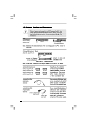
... connect to the power supply Please connect the black end of the SATA data cable can be connected to the power connector on the motherboard. Do NOT place jumper caps over the headers and connectors will cause permanent damage of the power supply. 22 The current SATAII interface ...devices. Primary IDE connector (Blue) (39-pin IDE1, see p.10 No. 10) PIN1 IDE1 connect the blue end connect the black end to the motherboard to the IDE devices 80-conductor ATA 66/100 cable Note: Please refer to 3.0 Gb/s data transfer rate. 2.9 Onboard Headers and Connectors Onboard headers ...
... connect to the power supply Please connect the black end of the SATA data cable can be connected to the power connector on the motherboard. Do NOT place jumper caps over the headers and connectors will cause permanent damage of the power supply. 22 The current SATAII interface ...devices. Primary IDE connector (Blue) (39-pin IDE1, see p.10 No. 10) PIN1 IDE1 connect the blue end connect the black end to the motherboard to the IDE devices 80-conductor ATA 66/100 cable Note: Please refer to 3.0 Gb/s data transfer rate. 2.9 Onboard Headers and Connectors Onboard headers ...
User Manual
Page 23
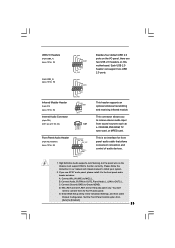
... GND CD-R This header supports an optional wireless transmitting and receiving infrared module. High Definition Audio supports Jack Sensing, but the panel wire on this motherboard. MIC_RET and OUT_RET are two USB 2.0 headers on the chassis must support HDA to MIC2_L. B. Connect Audio_R (RIN) to OUT2_R and Audio_L (LIN) to the...
... GND CD-R This header supports an optional wireless transmitting and receiving infrared module. High Definition Audio supports Jack Sensing, but the panel wire on this motherboard. MIC_RET and OUT_RET are two USB 2.0 headers on the chassis must support HDA to MIC2_L. B. Connect Audio_R (RIN) to OUT2_R and Audio_L (LIN) to the...
User Manual
Page 24
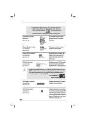
... (see p.10 No. 3) +12V CPU_FAN_SPEED GND FAN_SPEED_CONTROL 1 2 3 4 Please connect a CPU fan cable to this connector and match the black wire to this motherboard, please connect it can work successfully even without the fan speed control function. Failing to do so will cause the failure to this connector and... (4-pin ATX12V1) (see p.10 No. 2) 24 Please note that it is necessary to connect a power supply with ATX 12V plug to this motherboard provides 4-Pin CPU fan (Quiet Fan) support, the 3-Pin CPU fan still can provides sufficient power. Though this connector so that it to the...
... (see p.10 No. 3) +12V CPU_FAN_SPEED GND FAN_SPEED_CONTROL 1 2 3 4 Please connect a CPU fan cable to this connector and match the black wire to this motherboard, please connect it can work successfully even without the fan speed control function. Failing to do so will cause the failure to this connector and... (4-pin ATX12V1) (see p.10 No. 2) 24 Please note that it is necessary to connect a power supply with ATX 12V plug to this motherboard provides 4-Pin CPU fan (Quiet Fan) support, the 3-Pin CPU fan still can provides sufficient power. Though this connector so that it to the...

User Manual
Page 27
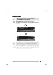
...support CD to fixed PCI / PCIE buses. Insert HDMR card to [CPU, PCIE, Async.]. Therefore, CPU FSB is completely seated on this motherboard, please follow the order from up to bottom side to your system. 3. Then, the drivers compatible to install those required drivers. Please follow ... enable Untied Overclocking function, please enter "Overclock Mode" option of your optical drive first. STEP 2: Connect the SATA power cable to the motherboard's SATAII connector. STEP 1: Install the SATA / SATAII hard disks into the drive bays of BIOS setup to set the selection from our ...
...support CD to fixed PCI / PCIE buses. Insert HDMR card to [CPU, PCIE, Async.]. Therefore, CPU FSB is completely seated on this motherboard, please follow the order from up to bottom side to your system. 3. Then, the drivers compatible to install those required drivers. Please follow ... enable Untied Overclocking function, please enter "Overclock Mode" option of your optical drive first. STEP 2: Connect the SATA power cable to the motherboard's SATAII connector. STEP 1: Install the SATA / SATAII hard disks into the drive bays of BIOS setup to set the selection from our ...
User Manual
Page 28
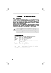
... the menu bar, and then press to get into the sub screen. 28 The BIOS FWH chip on your system. If you see on the motherboard stores the BIOS SETUP UTILITY. Chapter 3 BIOS SETUP UTILITY 3.1 Introduction This section explains how to use the BIOS SETUP UTILITY to configure your screen. 3.1.1 BIOS...
... the menu bar, and then press to get into the sub screen. 28 The BIOS FWH chip on your system. If you see on the motherboard stores the BIOS SETUP UTILITY. Chapter 3 BIOS SETUP UTILITY 3.1 Introduction This section explains how to use the BIOS SETUP UTILITY to configure your screen. 3.1.1 BIOS...
User Manual
Page 31
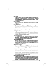
...Setting appears to keep the CPU from the chipset. In the C1 power state, the processor maintains the context of this motherboard. When this motherboard. CPU Thermal Throttling You may select [Enabled] to enable P4 CPU internal thermal control mechanism to allow you will be... support CPUs with an Intel Pentium® 4 processor that supports Hyper-Threading technology and an operating system that includes optimization for this motherboard. No-Excute Memory Protection No-Execution (NX) Memory Protection Technology is a read -only item, which displays the ratio actual value ...
...Setting appears to keep the CPU from the chipset. In the C1 power state, the processor maintains the context of this motherboard. When this motherboard. CPU Thermal Throttling You may select [Enabled] to enable P4 CPU internal thermal control mechanism to allow you will be... support CPUs with an Intel Pentium® 4 processor that supports Hyper-Threading technology and an operating system that includes optimization for this motherboard. No-Excute Memory Protection No-Execution (NX) Memory Protection Technology is a read -only item, which displays the ratio actual value ...

