
User Manual
Page 3
...CPU fan 15 2.5 Installation of Memory Modules (DIMM 16 2.6 Expansion Slots (PCI, HDMR, and PCI Express Slots) ....... 18 2.7 DVI Graphics-HDCP Card Installation Guide 19 2.8 Jumpers Setup 21 2.9 Onboard Headers and Connectors 22 2.10 SATAII Hard Disk Setup Guide 26 2.11...Installation 27 2.12 Driver Installation Guide 27 2.13 HDMR Card and Driver Installation 27 2.14 Untied Overclocking Technology 27 3 BIOS SETUP UTILITY 28 3.1 Introduction 28 3.1.1 BIOS Menu Bar 28 3.1.2 Navigation Keys 29 3.2 Main Screen 29 3.3 Advanced Screen 29 3.3.1 CPU Configuration 30 3.3.2 Chipset ...
...CPU fan 15 2.5 Installation of Memory Modules (DIMM 16 2.6 Expansion Slots (PCI, HDMR, and PCI Express Slots) ....... 18 2.7 DVI Graphics-HDCP Card Installation Guide 19 2.8 Jumpers Setup 21 2.9 Onboard Headers and Connectors 22 2.10 SATAII Hard Disk Setup Guide 26 2.11...Installation 27 2.12 Driver Installation Guide 27 2.13 HDMR Card and Driver Installation 27 2.14 Untied Overclocking Technology 27 3 BIOS SETUP UTILITY 28 3.1 Introduction 28 3.1.1 BIOS Menu Bar 28 3.1.2 Navigation Keys 29 3.2 Main Screen 29 3.3 Advanced Screen 29 3.3.1 CPU Configuration 30 3.3.2 Chipset ...

User Manual
Page 5
... you for a 3.5-in , 24.4 cm x 24.4 cm) ASRock ConRoe1333-DVI/H Quick Installation Guide ASRock ConRoe1333-DVI/H Support CD One 80-conductor Ultra ATA 66/100 IDE Ribbon Cable One Ribbon Cable for purchasing ASRock ConRoe1333-DVI/H motherboard, a reliable motherboard produced under ASRock's consistently stringent quality control. Because the motherboard specifications and the BIOS software might be updated, the content of this...
... you for a 3.5-in , 24.4 cm x 24.4 cm) ASRock ConRoe1333-DVI/H Quick Installation Guide ASRock ConRoe1333-DVI/H Support CD One 80-conductor Ultra ATA 66/100 IDE Ribbon Cable One Ribbon Cable for purchasing ASRock ConRoe1333-DVI/H motherboard, a reliable motherboard produced under ASRock's consistently stringent quality control. Because the motherboard specifications and the BIOS software might be updated, the content of this...
User Manual
Page 7
...IDE connector (supports 2 x IDE devices) - 1 x Floppy connector - 1 x IR header - 1 x COM port header - It should be done at your system. Connector BIOS Feature Support CD Hardware Monitor OS Certifications - CPU Fan Tachometer - Supports jumperfree - Overclocking may affect your system stability, or even cause damage to the components...Microsoft® Windows® 2000/XP/XP 64-bit/VistaTM/ VistaTM 64-bit compliant (see CAUTION 12) - 4Mb AMI BIOS - CPU Quiet Fan - AMI Legal BIOS - CPU/Chassis FAN connector - 20 pin ATX power connector - 4 pin 12V power connector -
...IDE connector (supports 2 x IDE devices) - 1 x Floppy connector - 1 x IR header - 1 x COM port header - It should be done at your system. Connector BIOS Feature Support CD Hardware Monitor OS Certifications - CPU Fan Tachometer - Supports jumperfree - Overclocking may affect your system stability, or even cause damage to the components...Microsoft® Windows® 2000/XP/XP 64-bit/VistaTM/ VistaTM 64-bit compliant (see CAUTION 12) - 4Mb AMI BIOS - CPU Quiet Fan - AMI Legal BIOS - CPU/Chassis FAN connector - 20 pin ATX power connector - 4 pin 12V power connector -

User Manual
Page 10
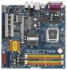
...) 26 PCI Express x16 Slot 11 Chassis Speaker Header (SPEAKER 1) 27 ATX Power Connector (ATXPWR1) 12 System Panel Header (PANEL1) 28 BIOS FWH Chip 13 Fourth SATAII Connector (SATAII_4; Red) 30 Infrared Module Header (IR1) 10 Red) 3 CPU Fan Connector (CPU_FAN1) 17 ...DVI Super IO 4Mb BIOS ATXPWR1 HDCP PCI EXPRESS PCIE1 ` Intel 945G Chipset PCIE2 PCI1 RoHS PCI2 7.1CH HD HDMR1 FLOPPY1 Intel ICH7 SATAII 1 USB4_5 IDE1 1 USB6_7 SATAII_3 SATAII_1 USB2.0 CHA_FAN1 SATAII_4 SATAII_2 SPEAKER1 1 PANEL 1 PLED PWRBTN 1 HDLED RESET Dual Core CPU Dual Channel ConRoe1333-DVI...
...) 26 PCI Express x16 Slot 11 Chassis Speaker Header (SPEAKER 1) 27 ATX Power Connector (ATXPWR1) 12 System Panel Header (PANEL1) 28 BIOS FWH Chip 13 Fourth SATAII Connector (SATAII_4; Red) 30 Infrared Module Header (IR1) 10 Red) 3 CPU Fan Connector (CPU_FAN1) 17 ...DVI Super IO 4Mb BIOS ATXPWR1 HDCP PCI EXPRESS PCIE1 ` Intel 945G Chipset PCIE2 PCI1 RoHS PCI2 7.1CH HD HDMR1 FLOPPY1 Intel ICH7 SATAII 1 USB4_5 IDE1 1 USB6_7 SATAII_3 SATAII_1 USB2.0 CHA_FAN1 SATAII_4 SATAII_2 SPEAKER1 1 PANEL 1 PLED PWRBTN 1 HDLED RESET Dual Core CPU Dual Channel ConRoe1333-DVI...

User Manual
Page 18
...HDMR slot is used for PCI Express cards with x16 lane width graphics cards or ASRock DVI Graphics-HDCP card. Installing an expansion card Step 1. Step 4. Fasten the card ...seated on PCI Express VGA card to PCIE1 (PCIE x16 slot) and adjust the "Internal Graphics Mode Select" BIOS option to [Enabled], the onboard VGA will be enabled, and the primary screen will be onboard VGA. ...2. You can only choose either PCI Express VGA card or DVI Graphics-HDCP card to install to the chassis with the slot and press firmly until the card is unplugged...
...HDMR slot is used for PCI Express cards with x16 lane width graphics cards or ASRock DVI Graphics-HDCP card. Installing an expansion card Step 1. Step 4. Fasten the card ...seated on PCI Express VGA card to PCIE1 (PCIE x16 slot) and adjust the "Internal Graphics Mode Select" BIOS option to [Enabled], the onboard VGA will be enabled, and the primary screen will be onboard VGA. ...2. You can only choose either PCI Express VGA card or DVI Graphics-HDCP card to install to the chassis with the slot and press firmly until the card is unplugged...
User Manual
Page 23
Connect Mic_IN (MIC) to Ground (GND). B. D. If you to install your system. 2. Enter BIOS Setup Utility. Enter Advanced Settings, and then select Chipset Configuration. Connect Ground (GND) to MIC2_L. E. Front Panel Audio Header (9-pin HD_AUDIO1) (see p.10 No. 24) ...
Connect Mic_IN (MIC) to Ground (GND). B. D. If you to install your system. 2. Enter BIOS Setup Utility. Enter Advanced Settings, and then select Chipset Configuration. Connect Ground (GND) to MIC2_L. E. Front Panel Audio Header (9-pin HD_AUDIO1) (see p.10 No. 24) ...

User Manual
Page 27
... drive first. Therefore, CPU FSB is completely seated on the support CD driver page. Please refer to your system. 3. STEP 4: Connect the other end of BIOS setup to set the selection from up to bottom side to [CPU, PCIE, Async.]. You may install SATA / SATAII hard disks on page 7 for internal...
... drive first. Therefore, CPU FSB is completely seated on the support CD driver page. Please refer to your system. 3. STEP 4: Connect the other end of BIOS setup to set the selection from up to bottom side to [CPU, PCIE, Async.]. You may install SATA / SATAII hard disks on page 7 for internal...
User Manual
Page 28
... screens and descriptions are for reference purpose only, and they may not exactly match what you wish to enter the BIOS SETUP UTILITY after POST, restart the system by pressing + + , or by turning the system off and then back on. Please press during the Power-On-...Self-Test (POST) to configure your screen. 3.1.1 BIOS Menu Bar The top of the screen has a menu bar with its test routines. You may also restart by pressing the reset button on the...
... screens and descriptions are for reference purpose only, and they may not exactly match what you wish to enter the BIOS SETUP UTILITY after POST, restart the system by pressing + + , or by turning the system off and then back on. Please press during the Power-On-...Self-Test (POST) to configure your screen. 3.1.1 BIOS Menu Bar The top of the screen has a menu bar with its test routines. You may also restart by pressing the reset button on the...

User Manual
Page 29
... UTILITY H/W Monitor Boot System Overview System Time System Date [14:00:09] [Thu 01/18/2007] BIOS Version : ConRoe1333-DVI/H BIOS P1.00 Processor Type : Intel (R) CPU 3.40 GHz (64bit supported) Processor Speed : 3400 MHz Microcode Update : F34/17 Cache Size : 1024KB Total Memory ...[SHIFT-TAB] to specify the system time. 3.1.2 Navigation Keys Please check the following table for all the settings To save changes and exit the BIOS SETUP UTILITY To jump to the Exit Screen or exit the current screen 3.2 Main Screen When you may set the configurations for the following items...
... UTILITY H/W Monitor Boot System Overview System Time System Date [14:00:09] [Thu 01/18/2007] BIOS Version : ConRoe1333-DVI/H BIOS P1.00 Processor Type : Intel (R) CPU 3.40 GHz (64bit supported) Processor Speed : 3400 MHz Microcode Update : F34/17 Cache Size : 1024KB Total Memory ...[SHIFT-TAB] to specify the system time. 3.1.2 Navigation Keys Please check the following table for all the settings To save changes and exit the BIOS SETUP UTILITY To jump to the Exit Screen or exit the current screen 3.2 Main Screen When you may set the configurations for the following items...

User Manual
Page 30
...is [133]. The default value is [Auto]. Spread Spectrum This item should always be [Auto] for better system stability. 30 BIOS SETUP UTILITY Main Advanced H/W Monitor Boot Security Exit Advanced Settings WARNING : Setting wrong values in this section may cause system to ...PCIE, Sync.] and [CPU, PCIE, Async.]. Setting wrong values in below sections may cause the system to malfunction. 3.3.1 CPU Configuration BIOS SETUP UTILITY Advanced CPU Configuration Overclock Mode CPU Frequency (MHz) PCIE Frequency (MHz) Boot Failure Guard Spread Spectrum Ratio Actual Value Enhance Halt...
...is [133]. The default value is [Auto]. Spread Spectrum This item should always be [Auto] for better system stability. 30 BIOS SETUP UTILITY Main Advanced H/W Monitor Boot Security Exit Advanced Settings WARNING : Setting wrong values in this section may cause system to ...PCIE, Sync.] and [CPU, PCIE, Async.]. Setting wrong values in below sections may cause the system to malfunction. 3.3.1 CPU Configuration BIOS SETUP UTILITY Advanced CPU Configuration Overclock Mode CPU Frequency (MHz) PCIE Frequency (MHz) Boot Failure Guard Spread Spectrum Ratio Actual Value Enhance Halt...

User Manual
Page 32
.... Processor can switch between multiple frequency and voltage points to the corresponding FSB frequency of this item to [Disable] if above issue occurs. 3.3.2 Chipset Configuration BIOS SETUP UTILITY Advanced Chipset Configuration DRAM Frequency [Auto] Flexibility Option [Disabled] Configure DRAM Timing by the contents in the SPD (Serial Presence Detect) device. It...
.... Processor can switch between multiple frequency and voltage points to the corresponding FSB frequency of this item to [Disable] if above issue occurs. 3.3.2 Chipset Configuration BIOS SETUP UTILITY Advanced Chipset Configuration DRAM Frequency [Auto] Flexibility Option [Disabled] Configure DRAM Timing by the contents in the SPD (Serial Presence Detect) device. It...

User Manual
Page 35
... field allows you plan to use this item to enable or disable RTC (Real Time Clock) to boot up when the power recovers. 3.3.3 ACPI Configuration BIOS SETUP UTILITY Advanced ACPI Configuration Suspend To RAM Restore on the system from the power-soft-off mode.
... field allows you plan to use this item to enable or disable RTC (Real Time Clock) to boot up when the power recovers. 3.3.3 ACPI Configuration BIOS SETUP UTILITY Advanced ACPI Configuration Suspend To RAM Restore on the system from the power-soft-off mode.

User Manual
Page 36
... IDE configuration for the device that you install legacy OS (Windows NT). If native OS (Windows 2000 / XP) is installed, please select [Enhanced]. 3.3.4 IDE Configuration BIOS SETUP UTILITY Advanced IDE Configuration ATA/IDE Configuration SATAII 1 SATAII 2 SATAII 3 SATAII 4 IDE1 Master IDE1 Slave [Enhanced] [Hard Disk] [Not Detected] [Not Detected] [Not Detected...
... IDE configuration for the device that you install legacy OS (Windows NT). If native OS (Windows 2000 / XP) is installed, please select [Enhanced]. 3.3.4 IDE Configuration BIOS SETUP UTILITY Advanced IDE Configuration ATA/IDE Configuration SATAII 1 SATAII 2 SATAII 3 SATAII 4 IDE1 Master IDE1 Slave [Enhanced] [Hard Disk] [Not Detected] [Not Detected] [Not Detected...

User Manual
Page 37
... hard disk performance by optimizing the hard disk timing. for compatible IDE devices. 37 After selecting the hard disk information into BIOS, use of the IDE device that you specify. BIOS SETUP UTILITY Advanced Primary IDE Master Device Vendor Size LBA Mode Block Mode PIO Mode Async DMA Ultra DMA S.M.A.R.T. Configuration options...
... hard disk performance by optimizing the hard disk timing. for compatible IDE devices. 37 After selecting the hard disk information into BIOS, use of the IDE device that you specify. BIOS SETUP UTILITY Advanced Primary IDE Master Device Vendor Size LBA Mode Block Mode PIO Mode Async DMA Ultra DMA S.M.A.R.T. Configuration options...

User Manual
Page 38
... or disable the PCI IDE BusMaster feature. 38 PCI IDE BusMaster Use this item to maximize the IDE hard disk data transfer rate. 3.3.5 PCIPnP Configuration BIOS SETUP UTILITY Advanced Advanced PCI / PnP Settings PCI Latency Timer PCI IDE BusMaster [32] [Enabled] Value in units of PCI clocks for PCI device latency...
... or disable the PCI IDE BusMaster feature. 38 PCI IDE BusMaster Use this item to maximize the IDE hard disk data transfer rate. 3.3.5 PCIPnP Configuration BIOS SETUP UTILITY Advanced Advanced PCI / PnP Settings PCI Latency Timer PCI IDE BusMaster [32] [Enabled] Value in units of PCI clocks for PCI device latency...

User Manual
Page 39
...], and [2E8 / IRQ3]. 39 3.3.6 Floppy Configuration In this item to set the address for the onboard infrared port or disable it . BIOS SETUP UTILITY Advanced Floppy Configuration Floppy A [1.44 MB 312"] Select the type of your floppy drive. Infrared Port Address Use this section, you...General Help Load Defaults Save and Exit Exit v02.54 (C) Copyright 1985-2005, American Megatrends, Inc. 3.3.7 Super IO Configuration BIOS SETUP UTILITY Advanced Configure Super IO Chipset OnBoard Floppy Controller Serial Port Address Infrared Port Address Parallel Port Address Parallel Port Mode EPP...
...], and [2E8 / IRQ3]. 39 3.3.6 Floppy Configuration In this item to set the address for the onboard infrared port or disable it . BIOS SETUP UTILITY Advanced Floppy Configuration Floppy A [1.44 MB 312"] Select the type of your floppy drive. Infrared Port Address Use this section, you...General Help Load Defaults Save and Exit Exit v02.54 (C) Copyright 1985-2005, American Megatrends, Inc. 3.3.7 Super IO Configuration BIOS SETUP UTILITY Advanced Configure Super IO Chipset OnBoard Floppy Controller Serial Port Address Infrared Port Address Parallel Port Address Parallel Port Mode EPP...

User Manual
Page 40
... the USB 2.0 support. EPP Version Use this item to enable or disable the use of the parallel port. Configuration options: [IRQ5] and [IRQ7]. 3.3.8 USB Configuration BIOS SETUP UTILITY Advanced USB Configuration USB Controller USB 2.0 Support Legacy USB Support [Enabled] [Enabled] [Disabled] To enable or disable the onboard USB controllers. +F1 F9...
... the USB 2.0 support. EPP Version Use this item to enable or disable the use of the parallel port. Configuration options: [IRQ5] and [IRQ7]. 3.3.8 USB Configuration BIOS SETUP UTILITY Advanced USB Configuration USB Controller USB 2.0 Support Legacy USB Support [Enabled] [Enabled] [Disabled] To enable or disable the onboard USB controllers. +F1 F9...

User Manual
Page 41
... this section, it allows you adjusting them. If you set the target fan speed. Target CPU Temperature ( C) The target temperature will operate in full speed. BIOS SETUP UTILITY Main Advanced H/W Monitor Boot Security Exit Hardware Health Event Monitoring CPU Temperature M / B Temperature : 37 C / 98 F : 31 C / 87 F Target Fan Speed Fast Middle Slow...
... this section, it allows you adjusting them. If you set the target fan speed. Target CPU Temperature ( C) The target temperature will operate in full speed. BIOS SETUP UTILITY Main Advanced H/W Monitor Boot Security Exit Hardware Health Event Monitoring CPU Temperature M / B Temperature : 37 C / 98 F : 31 C / 87 F Target Fan Speed Fast Middle Slow...

User Manual
Page 42
... From Onboard LAN Use this item to [On], it will automatically activate the Numeric Lock function after boot-up. 42 Main Advanced BIOS SETUP UTILITY H/W Monitor Boot Security Exit Boot Settings Boot Settings Configuration Configure Settings during System Boot. 1st Boot Device 2nd Boot Device ...Help F9 Load Defaults F10 Save and Exit ESC Exit v02.54 (C) Copyright 1985-2005, American Megatrends, Inc. 3.5.1 Boot Settings Configuration BIOS SETUP UTILITY Boot Boot Settings Configuration Boot From Onboard LAN Bootup Num-Lock [Disabled] [On] To enable or disable the boot from onboard...
... From Onboard LAN Use this item to [On], it will automatically activate the Numeric Lock function after boot-up. 42 Main Advanced BIOS SETUP UTILITY H/W Monitor Boot Security Exit Boot Settings Boot Settings Configuration Configure Settings during System Boot. 1st Boot Device 2nd Boot Device ...Help F9 Load Defaults F10 Save and Exit ESC Exit v02.54 (C) Copyright 1985-2005, American Megatrends, Inc. 3.5.1 Boot Settings Configuration BIOS SETUP UTILITY Boot Boot Settings Configuration Boot From Onboard LAN Bootup Num-Lock [Disabled] [On] To enable or disable the boot from onboard...

User Manual
Page 43
BIOS SETUP UTILITY Main Advanced H/W Monitor Boot Security Exit Security Settings Supervisor Password : Not Installed User Password : Not Installed Change Supervisor Password Change User Password Install or Change the password. Select Screen Select Item Enter Change F1 General Help F9 Load Defaults F10 Save and Exit ESC Exit v02.54 (C) Copyright 1985-2005, American Megatrends, Inc. 43 For the user password, you may also clear it. 3.6 Security Screen In this section, you may set or change the supervisor/user password for the system.
BIOS SETUP UTILITY Main Advanced H/W Monitor Boot Security Exit Security Settings Supervisor Password : Not Installed User Password : Not Installed Change Supervisor Password Change User Password Install or Change the password. Select Screen Select Item Enter Change F1 General Help F9 Load Defaults F10 Save and Exit ESC Exit v02.54 (C) Copyright 1985-2005, American Megatrends, Inc. 43 For the user password, you may also clear it. 3.6 Security Screen In this section, you may set or change the supervisor/user password for the system.


