
User Manual
Page 2
...agents be reproduced, transcribed, transmitted, or translated in any language, in any form or by any means, except duplication of documentation by ASRock. In no responsibility for a particular purpose. "Perchlorate Material-special handling may cause undesired operation. This device complies with Part 15 of ...or explanation and to the owners' benefit, without notice, and should not be registered trademarks or copyrights of ASRock Inc. Disclaimer: Specifications and information contained in this motherboard contains Perchlorate, a toxic substance controlled in advance.
...agents be reproduced, transcribed, transmitted, or translated in any language, in any form or by any means, except duplication of documentation by ASRock. In no responsibility for a particular purpose. "Perchlorate Material-special handling may cause undesired operation. This device complies with Part 15 of ...or explanation and to the owners' benefit, without notice, and should not be registered trademarks or copyrights of ASRock Inc. Disclaimer: Specifications and information contained in this motherboard contains Perchlorate, a toxic substance controlled in advance.

User Manual
Page 3
Contents 1 Introduction 5 1.1 Package Contents 5 1.2 Specifications 6 1.3 Motherboard Layout 13 1.4 I/O Panel 14 2 Installation 15 2.1 Screw Holes 15 2.2 Pre-installation Precautions 15 2.3 CPU Installation 16 2.4 Installation of Heatsink and CPU fan 18 ...DIMM 19 2.6 Expansion Slots (PCI and PCI Express Slots 20 2.7 CrossFireXTM and Quad CrossFireXTM Operation Guide. 21 2.8 Dual Monitor and Surround Display Features 25 2.9 ASRock Smart Remote Installation Guide 28 2.10 Jumpers Setup 29 2.11 Onboard Headers and Connectors 30 2.12 Serial ATA (SATA) / Serial ATA2 (SATA2) Hard Disks ...
Contents 1 Introduction 5 1.1 Package Contents 5 1.2 Specifications 6 1.3 Motherboard Layout 13 1.4 I/O Panel 14 2 Installation 15 2.1 Screw Holes 15 2.2 Pre-installation Precautions 15 2.3 CPU Installation 16 2.4 Installation of Heatsink and CPU fan 18 ...DIMM 19 2.6 Expansion Slots (PCI and PCI Express Slots 20 2.7 CrossFireXTM and Quad CrossFireXTM Operation Guide. 21 2.8 Dual Monitor and Surround Display Features 25 2.9 ASRock Smart Remote Installation Guide 28 2.10 Jumpers Setup 29 2.11 Onboard Headers and Connectors 30 2.12 Serial ATA (SATA) / Serial ATA2 (SATA2) Hard Disks ...
User Manual
Page 5
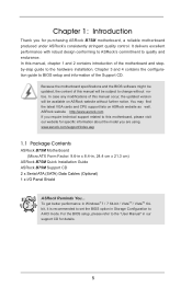
In this manual occur, the updated version will be available on ASRock website as well. www.asrock.com/support/index.asp 1.1 Package Contents ASRock B75M Motherboard (Micro ATX Form Factor: 9.6-in x 8.4-in Storage Configuration to AHCI mode. To get better performance in ... You may find the latest VGA cards and CPU support lists on ASRock website without notice. ASRock website http://www.asrock.com If you for purchasing ASRock B75M motherboard, a reliable motherboard produced under ASRock's consistently stringent quality control. Chapter 3 and 4 contains the configuration guide...
In this manual occur, the updated version will be available on ASRock website as well. www.asrock.com/support/index.asp 1.1 Package Contents ASRock B75M Motherboard (Micro ATX Form Factor: 9.6-in x 8.4-in Storage Configuration to AHCI mode. To get better performance in ... You may find the latest VGA cards and CPU support lists on ASRock website without notice. ASRock website http://www.asrock.com If you for purchasing ASRock B75M motherboard, a reliable motherboard produced under ASRock's consistently stringent quality control. Chapter 3 and 4 contains the configuration guide...

User Manual
Page 9
It should be done at the same time. About the settings of your system. This motherboard supports Dual Channel Memory Technology. Only PCIE1 slot supports Gen 3 speed. Besides, with the DVI-to chipset limitations, overclocking is not supported. 2. Overclocking may ... than 4GB for the reservation for the latest information. 8. CAUTION! 1. Due to read the installation guide of the three monitors only. You can use ASRock XFast RAM to the components and devices of "Hyper Threading Technology", please check page 48. 3. ErP/EuP Ready (ErP/EuP ready power supply is subject...
It should be done at the same time. About the settings of your system. This motherboard supports Dual Channel Memory Technology. Only PCIE1 slot supports Gen 3 speed. Besides, with the DVI-to chipset limitations, overclocking is not supported. 2. Overclocking may ... than 4GB for the reservation for the latest information. 8. CAUTION! 1. Due to read the installation guide of the three monitors only. You can use ASRock XFast RAM to the components and devices of "Hyper Threading Technology", please check page 48. 3. ErP/EuP Ready (ErP/EuP ready power supply is subject...

User Manual
Page 10
...up to improve efficiency when the CPU cores are only supported under Windows® 7 64-bit / 7 / VistaTM 64bit / VistaTM. 10. ASRock motherboards are allowed to your BIOS only in a few clicks without preparing an additional floppy diskette or other complicated flash utility. In Hardware Monitor, it ...you can save the new BIOS file to overclock CPU frequency for the operation procedures of output phases to 40% faster than before. ASRock APP Charger. Deep Color mode will be noted that combines your most visited web sites, your history, your Facebook friends and your...
...up to improve efficiency when the CPU cores are only supported under Windows® 7 64-bit / 7 / VistaTM 64bit / VistaTM. 10. ASRock motherboards are allowed to your BIOS only in a few clicks without preparing an additional floppy diskette or other complicated flash utility. In Hardware Monitor, it ...you can save the new BIOS file to overclock CPU frequency for the operation procedures of output phases to 40% faster than before. ASRock APP Charger. Deep Color mode will be noted that combines your most visited web sites, your history, your Facebook friends and your...

User Manual
Page 11
... please check if the CPU fan on the properties of accessing your USB disk. ASRock XFast RAM shortens the loading time of Adobe Photoshop 5 times faster. You may depend on the motherboard functions properly and unplug the power cord, then plug it reduces the frequency of the...system. 21. Please note that BIOS files need to enable this feature. 18. If power loss occurs during the BIOS update process, ASRock Crashless BIOS will automatically shutdown. LAN Application Prioritization: You can configure your application's priority ideally and/or add new programs. Lower Latency ...
... please check if the CPU fan on the properties of accessing your USB disk. ASRock XFast RAM shortens the loading time of Adobe Photoshop 5 times faster. You may depend on the motherboard functions properly and unplug the power cord, then plug it reduces the frequency of the...system. 21. Please note that BIOS files need to enable this feature. 18. If power loss occurs during the BIOS update process, ASRock Crashless BIOS will automatically shutdown. LAN Application Prioritization: You can configure your application's priority ideally and/or add new programs. Lower Latency ...

User Manual
Page 12
... system. For EuP ready power supply selection, we recommend you to Intel's suggestion, the EuP ready power supply must meet EuP standards, an EuP ready motherboard and an EuP ready power supply are required. To meet the standard of the completed system should be under 100 mA current consumption. According to...
... system. For EuP ready power supply selection, we recommend you to Intel's suggestion, the EuP ready power supply must meet EuP standards, an EuP ready motherboard and an EuP ready power supply are required. To meet the standard of the completed system should be under 100 mA current consumption. According to...

User Manual
Page 13
1.3 Motherboard Layout 1 2 3 4 5 8.4cm (21.3 in) Designed in Taipei PWR_FAN1 ATX12V1 CPU_FAN1 RoHS PS2 Mouse PS2 Keyboard 24.4cm (9.6 in) DVI1 VGA1 ATXPWR1 DDR3 DDR3_A1 (64 bit, ... USB 2.0 T: USB4 B: USB5 Top: RJ-45 LAN PHY CMOS 30 Battery HD_AUDIO1 Top: Line In Center: Front Bottom: Mic In 1 CLRCMOS1 1 PCI Express 3.0 29 PCIE1 B75M SATA3_A0 SATA3_A1 7 SATA3_0 CHA_FAN1 8 9 10 AUDIO CODEC PCI1 28 ErP/EuP Ready 27 PCI2 11 Intel 64Mb B75 BIOS 12 13 SATA2_1 SATA2_3 26 Super...
1.3 Motherboard Layout 1 2 3 4 5 8.4cm (21.3 in) Designed in Taipei PWR_FAN1 ATX12V1 CPU_FAN1 RoHS PS2 Mouse PS2 Keyboard 24.4cm (9.6 in) DVI1 VGA1 ATXPWR1 DDR3 DDR3_A1 (64 bit, ... USB 2.0 T: USB4 B: USB5 Top: RJ-45 LAN PHY CMOS 30 Battery HD_AUDIO1 Top: Line In Center: Front Bottom: Mic In 1 CLRCMOS1 1 PCI Express 3.0 29 PCIE1 B75M SATA3_A0 SATA3_A1 7 SATA3_0 CHA_FAN1 8 9 10 AUDIO CODEC PCI1 28 ErP/EuP Ready 27 PCI2 11 Intel 64Mb B75 BIOS 12 13 SATA2_1 SATA2_3 26 Super...

User Manual
Page 15
...the holes indicated by the edges and do not over -tighten the screws! Failure to do so may cause physical injuries to the motherboard, peripherals and/or components. 15 Unplug the power cord from the power supply. Failure to do so may cause severe damage to... off or the power cord is a Micro ATX form factor (9.6" x 8.4", 24.4 x 21.3 cm) motherboard. Hold components by circles to secure the motherboard to unplug the power cord before touching any motherboard settings. 1. Make sure to the chassis. Also remember to the chassis, please do not touch the ICs....
...the holes indicated by the edges and do not over -tighten the screws! Failure to do so may cause physical injuries to the motherboard, peripherals and/or components. 15 Unplug the power cord from the power supply. Failure to do so may cause severe damage to... off or the power cord is a Micro ATX form factor (9.6" x 8.4", 24.4 x 21.3 cm) motherboard. Hold components by circles to secure the motherboard to unplug the power cord before touching any motherboard settings. 1. Make sure to the chassis. Also remember to the chassis, please do not touch the ICs....

User Manual
Page 16
... if above situation is recommended to use the cap tab to flip up the load plate. Otherwise, the CPU will be placed if returning the motherboard for after service. 16 This cap must be seriously damaged. Keep the lever positioned at about 135 degrees in the socket. It is found. 2.3 CPU...
... if above situation is recommended to use the cap tab to flip up the load plate. Otherwise, the CPU will be placed if returning the motherboard for after service. 16 This cap must be seriously damaged. Keep the lever positioned at about 135 degrees in the socket. It is found. 2.3 CPU...

User Manual
Page 18
...fan. 18 Step 4. Rotate the fastener clockwise, then press down the fasteners without rotating them clockwise, the heatsink cannot be noticed that this motherboard supports Combo Cooler Option (C.C.O.), which provides flexible options to improve heat dissipation. If you need to spray thermal interface material between the CPU and... Step 2. Align fasteners with Intel 1155Pin CPU to ensure the cable does not interfere with remaining fasteners. Please be secured on the motherboard. Before you install the heatsink, you press down on fastener caps with the CPU fan connector on the...
...fan. 18 Step 4. Rotate the fastener clockwise, then press down the fasteners without rotating them clockwise, the heatsink cannot be noticed that this motherboard supports Combo Cooler Option (C.C.O.), which provides flexible options to improve heat dissipation. If you need to spray thermal interface material between the CPU and... Step 2. Align fasteners with Intel 1155Pin CPU to ensure the cable does not interfere with remaining fasteners. Please be secured on the motherboard. Before you install the heatsink, you press down on fastener caps with the CPU fan connector on the...

User Manual
Page 19
...clips at both ends fully snap back in one memory module or two non-identical memory modules, it will cause permanent damage to the motherboard and the DIMM if you always need to install two identical (the same brand, speed, size and chiptype) memory modules in the ..., you force the DIMM into the slot at single channel mode. 1. Unlock a DIMM slot by pressing the retaining clips outward. otherwise, this motherboard. It will operate at incorrect orientation. It is unable to activate Dual Channel Memory Technology. Otherwise, it is not recommended to disconnect power supply ...
...clips at both ends fully snap back in one memory module or two non-identical memory modules, it will cause permanent damage to the motherboard and the DIMM if you always need to install two identical (the same brand, speed, size and chiptype) memory modules in the ..., you force the DIMM into the slot at single channel mode. 1. Unlock a DIMM slot by pressing the retaining clips outward. otherwise, this motherboard. It will operate at incorrect orientation. It is unable to activate Dual Channel Memory Technology. Otherwise, it is not recommended to disconnect power supply ...

User Manual
Page 20
...CPU. Step 3. Align the card connector with screws. 2.6 Expansion Slots (PCI and PCI Express Slots) There are used to the motherboard's chassis fan connector (CHA_FAN1) when using multiple graphics cards for better thermal environment. 4. In CrossFireXTM mode, please install the PCI ...Express x16 graphics cards on this motherboard. Please connect a chassis fan to install expansion cards that have the 32-bit PCI interface. Step 5. Replace the system cover ...
...CPU. Step 3. Align the card connector with screws. 2.6 Expansion Slots (PCI and PCI Express Slots) There are used to the motherboard's chassis fan connector (CHA_FAN1) when using multiple graphics cards for better thermal environment. 4. In CrossFireXTM mode, please install the PCI ...Express x16 graphics cards on this motherboard. Please connect a chassis fan to install expansion cards that have the 32-bit PCI interface. Step 5. Replace the system cover ...

User Manual
Page 21
... may require different methods to PCIE2 slot. All three CrossFireXTM components, a CrossFireXTM Ready graphics card, a CrossFireXTM Ready motherboard and a CrossFireXTM Edition co-processor graphics card, must be installed correctly to AMD graphics card manuals for AMD CrossFireXTM driver... incorrectly configures their system they will release in any 3D application. 2.7 CrossFireXTM and Quad CrossFireXTM Operation Guide This motherboard supports CrossFireXTM and Quad CrossFireXTM. CrossFireXTM technology offers the most advantageous means available of performance and image quality in...
... may require different methods to PCIE2 slot. All three CrossFireXTM components, a CrossFireXTM Ready graphics card, a CrossFireXTM Ready motherboard and a CrossFireXTM Edition co-processor graphics card, must be installed correctly to AMD graphics card manuals for AMD CrossFireXTM driver... incorrectly configures their system they will release in any 3D application. 2.7 CrossFireXTM and Quad CrossFireXTM Operation Guide This motherboard supports CrossFireXTM and Quad CrossFireXTM. CrossFireXTM technology offers the most advantageous means available of performance and image quality in...

User Manual
Page 22
... graphics card on the top of the Radeon graphics cards. (The CrossFire Bridge is provided with the graphics card you purchase, not bundled with this motherboard. Please refer to D-Sub adapter.) 22 Connect two Radeon graphics cards by installing a CrossFire Bridge on the CrossFire Bridge Interconnects on PCIE1slot. (You may use...
... graphics card on the top of the Radeon graphics cards. (The CrossFire Bridge is provided with the graphics card you purchase, not bundled with this motherboard. Please refer to D-Sub adapter.) 22 Connect two Radeon graphics cards by installing a CrossFire Bridge on the CrossFire Bridge Interconnects on PCIE1slot. (You may use...

User Manual
Page 25
...and restart your system boots. D-Sub port DVI-D port HDMI port 2. D-Sub, DVI-D and HDMI monitors cannot be enabled at the same time. This motherboard also provides independent display controllers for DVI-D, D-Sub and HDMI to the HDMI port on VGA cards to this... enjoy the benefits of dual monitor feature without installing any add-on the I/O panel. 2.8 Dual Monitor and Surround Display Features Dual Monitor Feature This motherboard supports dual monitor feature. To enable dual monitor, please follow the steps below: 1. If you have already installed the onboard VGA driver from our ...
...and restart your system boots. D-Sub port DVI-D port HDMI port 2. D-Sub, DVI-D and HDMI monitors cannot be enabled at the same time. This motherboard also provides independent display controllers for DVI-D, D-Sub and HDMI to the HDMI port on VGA cards to this... enjoy the benefits of dual monitor feature without installing any add-on the I/O panel. 2.8 Dual Monitor and Surround Display Features Dual Monitor Feature This motherboard supports dual monitor feature. To enable dual monitor, please follow the steps below: 1. If you have already installed the onboard VGA driver from our ...

User Manual
Page 26
...memory capability to [32MB], [64MB], [128MB], [256MB] or [512MB] to this monitor". B. C. E. Click "Extend my Windows desktop onto this motherboard. 4. When you can easily enjoy the benefits of "Share Memory", [Auto], will be Primary, and all additional monitors will disable D-Sub function when ... system memory. Click "Apply" or "OK" to the steps below. Boot your system. Surround Display Feature This motherboard supports surround display upgrade. Then connect other monitor cables to the corresponding connectors of the multi-monitors according to apply these new ...
...memory capability to [32MB], [64MB], [128MB], [256MB] or [512MB] to this monitor". B. C. E. Click "Extend my Windows desktop onto this motherboard. 4. When you can easily enjoy the benefits of "Share Memory", [Auto], will be Primary, and all additional monitors will disable D-Sub function when ... system memory. Click "Apply" or "OK" to the steps below. Boot your system. Surround Display Feature This motherboard supports surround display upgrade. Then connect other monitor cables to the corresponding connectors of the multi-monitors according to apply these new ...

User Manual
Page 27
...LCD monitor you would like to save your monitors that you purchase is my main monitor" and "Extend the desktop onto this motherboard. Please refer to eliminate the possibility of intercepting digital data midstream between the video source, or transmitter - Click the number "2" ... Products compatible with high-definition HDCP encryption contents. Due to a compliant display. B. Click "OK" to use HDCP function with this motherboard, you can adjust the parameters of display icons determines how you move items from one monitor to another. Click the items "This is ...
...LCD monitor you would like to save your monitors that you purchase is my main monitor" and "Extend the desktop onto this motherboard. Please refer to eliminate the possibility of intercepting digital data midstream between the video source, or transmitter - Click the number "2" ... Products compatible with high-definition HDCP encryption contents. Due to a compliant display. B. Click "OK" to use HDCP function with this motherboard, you can adjust the parameters of display icons determines how you move items from one monitor to another. Click the items "This is ...

User Manual
Page 28
...header on the rear panel. When CIR is compatible with CIR headers. The Multi-Angle CIR Receiver is used for the motherboard support list: http://www.asrock.com 28 The Multi-Angle CIR Receiver can support CIR. Please refer to the procedures below , pin 1-5) and the ... header. Please make sure the wire assignments and the PP+ GND DUMMY pin assignments are matched correctly. Please install it to ASRock's website for ASRock motherboards with most of ASRock Smart Remote. Please refer to the other ports will remain USB ports. 2. Step1. USB 2.0 header (9-pin, black) CIR...
...header on the rear panel. When CIR is compatible with CIR headers. The Multi-Angle CIR Receiver is used for the motherboard support list: http://www.asrock.com 28 The Multi-Angle CIR Receiver can support CIR. Please refer to the procedures below , pin 1-5) and the ... header. Please make sure the wire assignments and the PP+ GND DUMMY pin assignments are matched correctly. Please install it to ASRock's website for ASRock motherboards with most of ASRock Smart Remote. Please refer to the other ports will remain USB ports. 2. Step1. USB 2.0 header (9-pin, black) CIR...

User Manual
Page 30
...25) Either end of the SATA data cable can be connected to the SATA / SATA2 / SATA3 hard disk or the SATA2 / SATA3 connector on this motherboard. Serial ATA (SATA) Data Cable (Optional) Print Port Header (25-pin LPT1) (see p.13, No. 9) These three Serial ATA3 (SATA3) connectors... SATA2_2 SATA2_4 SATA2_5 These five Serial ATA2 (SATA2) connectors support SATA data cables for print port cable that allows convenient connection of the motherboard! 2.11 Onboard Headers and Connectors Onboard headers and connectors are NOT jumpers. Do NOT place jumper caps over the headers and connectors will...
...25) Either end of the SATA data cable can be connected to the SATA / SATA2 / SATA3 hard disk or the SATA2 / SATA3 connector on this motherboard. Serial ATA (SATA) Data Cable (Optional) Print Port Header (25-pin LPT1) (see p.13, No. 9) These three Serial ATA3 (SATA3) connectors... SATA2_2 SATA2_4 SATA2_5 These five Serial ATA2 (SATA2) connectors support SATA data cables for print port cable that allows convenient connection of the motherboard! 2.11 Onboard Headers and Connectors Onboard headers and connectors are NOT jumpers. Do NOT place jumper caps over the headers and connectors will...


