User Manual
Page 5
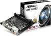
... utilities. ASRock website http://www.asrock.com. 1.1 Package Contents • ASRock AM1H-ITX Motherboard (Mini-ITX Form Factor) • ASRock AM1H-ITX Quick Installation Guide • ASRock AM1H-ITX Support CD • 2 x Serial ATA (SATA) Data Cables (Optional) • 1 x Serial ATA (SATA) Power Cable (Optional) • 1 x WiFi Module Screw • 1 x I/O Panel Shield 1 English Chapter 3 contains the operation guide of this manual will be...
... utilities. ASRock website http://www.asrock.com. 1.1 Package Contents • ASRock AM1H-ITX Motherboard (Mini-ITX Form Factor) • ASRock AM1H-ITX Quick Installation Guide • ASRock AM1H-ITX Support CD • 2 x Serial ATA (SATA) Data Cables (Optional) • 1 x Serial ATA (SATA) Power Cable (Optional) • 1 x WiFi Module Screw • 1 x I/O Panel Shield 1 English Chapter 3 contains the operation guide of this manual will be...
User Manual
Page 21
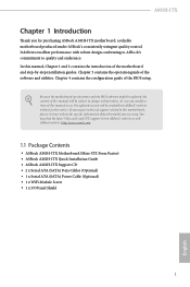
... that the CPU and the heatsink are securely fastened and in good contact with each other. Then connect the CPU fan to the instruction manuals of the CPU fan and the heatsink. For proper installation, please kindly refer to the CPU FAN connector. Please turn off the power or ...power cord before changing a CPU or heatsink. 17 English You also need to spray thermal grease between the CPU and the heatsink to dissipate heat. AM1H-ITX 2.2 Installing the CPU Fan and Heatsink After you install the CPU into this motherboard, it is necessary to install a larger heatsink and cooling fan ...
... that the CPU and the heatsink are securely fastened and in good contact with each other. Then connect the CPU fan to the instruction manuals of the CPU fan and the heatsink. For proper installation, please kindly refer to the CPU FAN connector. Please turn off the power or ...power cord before changing a CPU or heatsink. 17 English You also need to spray thermal grease between the CPU and the heatsink to dissipate heat. AM1H-ITX 2.2 Installing the CPU Fan and Heatsink After you install the CPU into this motherboard, it is necessary to install a larger heatsink and cooling fan ...
User Manual
Page 28
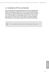
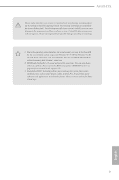
... Power Connector (24-pin ATXPWR1) (see p.10, No. 5) 24 DUMMY SPEAKER 1 +5V DUMMY Please connect the chassis speaker to the "FrontMic" Tab in our manual and chassis manual to OUT2_L. FAN_SPEED_CONTROL CPU_FAN_SPEED +12V GND 1 2 3 4 This motherboard provides a 4-Pin CPU fan (Quiet Fan) connector. MIC_RET and OUT_RET are for the AC'97 audio...
... Power Connector (24-pin ATXPWR1) (see p.10, No. 5) 24 DUMMY SPEAKER 1 +5V DUMMY Please connect the chassis speaker to the "FrontMic" Tab in our manual and chassis manual to OUT2_L. FAN_SPEED_CONTROL CPU_FAN_SPEED +12V GND 1 2 3 4 This motherboard provides a 4-Pin CPU fan (Quiet Fan) connector. MIC_RET and OUT_RET are for the AC'97 audio...
User Manual
Page 42
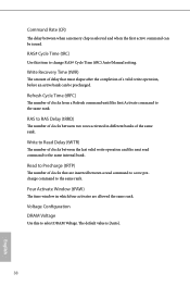
... Window (tFAW) The time window in different banks of clocks from a Refresh command until the first Activate command to change RAS# Cycle Time (tRC) Auto/Manual setting. The default value is selected and when the first active command can be issued. Write to select DRAM Voltage. RAS# Cycle Time (tRC) Use...
... Window (tFAW) The time window in different banks of clocks from a Refresh command until the first Activate command to change RAS# Cycle Time (tRC) Auto/Manual setting. The default value is selected and when the first active command can be issued. Write to select DRAM Voltage. RAS# Cycle Time (tRC) Use...

Quick Installation Guide
Page 5
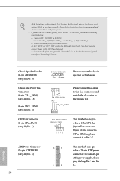
... RJ-45 Port** 5 Central / Bass (Orange) 6 Rear Speaker (Black) 7 Line In (Light Blue) 8 Front Speaker (Lime)*** No. You can only choose either one of user manual in the support CD. ** There are two LEDs on each LAN port. Please refer to the table below for the LAN port LED indications. Please... LED Status Off Blinking On Description No Link Data Activity Link Speed LED Status Off Orange Green Description 10Mbps connection 100Mbps connection 1Gbps connection 3 English AM1H-ITX I/O Panel 57 1 2 3 4 68 15 14 13 12 11 10 9 No.
... RJ-45 Port** 5 Central / Bass (Orange) 6 Rear Speaker (Black) 7 Line In (Light Blue) 8 Front Speaker (Lime)*** No. You can only choose either one of user manual in the support CD. ** There are two LEDs on each LAN port. Please refer to the table below for the LAN port LED indications. Please... LED Status Off Blinking On Description No Link Data Activity Link Speed LED Status Off Orange Green Description 10Mbps connection 100Mbps connection 1Gbps connection 3 English AM1H-ITX I/O Panel 57 1 2 3 4 68 15 14 13 12 11 10 9 No.
Quick Installation Guide
Page 11
...than 4GB for the reservation for system usage under Windows® 8 / 7 / XP. You can only choose either one of user manual in the BIOS, applying Untied Overclocking Technology, or using thirdparty overclocking tools. It needs third-party softwares and applications to utilize the memory ...Cloud topic. 9 English For Windows® 64-bit OS with overclocking, including adjusting the setting in the support CD. 3. AM1H-ITX Please realize that Windows® cannot use ASRock XFast RAM to utilize this system from remote mobile devices, such as smart phones, tables, or other PCs.
...than 4GB for the reservation for system usage under Windows® 8 / 7 / XP. You can only choose either one of user manual in the BIOS, applying Untied Overclocking Technology, or using thirdparty overclocking tools. It needs third-party softwares and applications to utilize the memory ...Cloud topic. 9 English For Windows® 64-bit OS with overclocking, including adjusting the setting in the support CD. 3. AM1H-ITX Please realize that Windows® cannot use ASRock XFast RAM to utilize this system from remote mobile devices, such as smart phones, tables, or other PCs.
Quick Installation Guide
Page 19
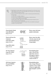
...2. Please follow the instructions in the Realtek Control panel and adjust "Recording Volume". You don't need to the "FrontMic" Tab in our manual and chassis manual to function correctly. To activate the front mic, go to connect them for the HD audio panel only. ATX Power Connector (24-pin ...SPEAKER1) (see p.1, No. 2) GND +12V FAN_SPEED FAN_SPEED_CONTROL Please connect fan cables to the fan connectors and match the black wire to Ground (GND). AM1H-ITX 1. E. If you plan to connect a 3-Pin CPU fan, please connect it to the front panel audio header by the steps below: A.
...2. Please follow the instructions in the Realtek Control panel and adjust "Recording Volume". You don't need to the "FrontMic" Tab in our manual and chassis manual to function correctly. To activate the front mic, go to connect them for the HD audio panel only. ATX Power Connector (24-pin ...SPEAKER1) (see p.1, No. 2) GND +12V FAN_SPEED FAN_SPEED_CONTROL Please connect fan cables to the fan connectors and match the black wire to Ground (GND). AM1H-ITX 1. E. If you plan to connect a 3-Pin CPU fan, please connect it to the front panel audio header by the steps below: A.
