User Manual
Page 1
All rights reserved. 1 ALiveSATA2-GLAN User Manual Version 1.4 Published February 2007 Copyright©2007 ASRock INC.
All rights reserved. 1 ALiveSATA2-GLAN User Manual Version 1.4 Published February 2007 Copyright©2007 ASRock INC.
User Manual
Page 2
... been advised of the possibility of the FCC Rules. CALIFORNIA, USA ONLY The Lithium battery adopted on this manual. ASRock assumes no event shall ASRock, its directors, officers, employees, or agents be liable for any errors or omissions that may cause undesired operation... should not be constructed as a commitment by ASRock. Products and corporate names appearing in this manual may apply, see www.dtsc.ca.gov/hazardouswaste/perchlorate" ASRock Website: http://www.asrock.com 2 With respect to the contents of this manual, ASRock does not provide warranty of any means, except...
... been advised of the possibility of the FCC Rules. CALIFORNIA, USA ONLY The Lithium battery adopted on this manual. ASRock assumes no event shall ASRock, its directors, officers, employees, or agents be liable for any errors or omissions that may cause undesired operation... should not be constructed as a commitment by ASRock. Products and corporate names appearing in this manual may apply, see www.dtsc.ca.gov/hazardouswaste/perchlorate" ASRock Website: http://www.asrock.com 2 With respect to the contents of this manual, ASRock does not provide warranty of any means, except...
User Manual
Page 5
Introduction Thank you for purchasing ASRock ALiveSATA2-GLAN motherboard, a reliable motherboard produced under ASRock's consistently stringent quality control. Because the motherboard specifications and the BIOS software might be updated, the content of this manual will be subject to change without further notice. Chapter 3 and 4 contain the configuration guide to BIOS setup and information of the motherboard...
Introduction Thank you for purchasing ASRock ALiveSATA2-GLAN motherboard, a reliable motherboard produced under ASRock's consistently stringent quality control. Because the motherboard specifications and the BIOS software might be updated, the content of this manual will be subject to change without further notice. Chapter 3 and 4 contain the configuration guide to BIOS setup and information of the motherboard...
User Manual
Page 13
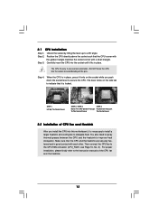
... Lock To The Socket Corner The Socket Lever 2.2 Installation of the CPU fan and the heatsink. 13 Then connect the CPU fan to the instruction manuals of CPU Fan and Heatsink After you push down the socket lever to dissipate heat. For proper installation, please kindly refer to the CPU FAN...
... Lock To The Socket Corner The Socket Lever 2.2 Installation of the CPU fan and the heatsink. 13 Then connect the CPU fan to the instruction manuals of CPU Fan and Heatsink After you push down the socket lever to dissipate heat. For proper installation, please kindly refer to the CPU FAN...
User Manual
Page 20
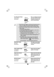
... Audio supports Jack Sensing, but the panel wire on the lower right hand taskbar to the ground pin. Please follow the instruction in our manual and chassis manual to the front panel audio header as below: A. If you use AC'97 audio panel, please install it to install your system. 2. C. D. System Panel...
... Audio supports Jack Sensing, but the panel wire on the lower right hand taskbar to the ground pin. Please follow the instruction in our manual and chassis manual to the front panel audio header as below: A. If you use AC'97 audio panel, please install it to install your system. 2. C. D. System Panel...
User Manual
Page 22
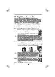
...please refer to page 21. Step 2. Connect the black end (A) of HDMI_SPDIF header and HDMI_SPDIF cable connectors, please refer to the user manual of the HDMI VGA card you install. For the pin definition of HDMI_SPDIF connectors on this picture shows the wrong example of connecting HDMI_SPDIF... the system to HDMI device, such as a digital television (DTV). Connect the HDMI output connector on page 16. Please refer to the user manual of HDMI VGA card, please refer to the HDMI_SPDIF connector of HDMI VGA card vendor. Incorrect connection may be damaged. Step 3. Step 5. Please...
...please refer to page 21. Step 2. Connect the black end (A) of HDMI_SPDIF header and HDMI_SPDIF cable connectors, please refer to the user manual of the HDMI VGA card you install. For the pin definition of HDMI_SPDIF connectors on this picture shows the wrong example of connecting HDMI_SPDIF... the system to HDMI device, such as a digital television (DTV). Connect the HDMI output connector on page 16. Please refer to the user manual of HDMI VGA card, please refer to the HDMI_SPDIF connector of HDMI VGA card vendor. Incorrect connection may be damaged. Step 3. Step 5. Please...
User Manual
Page 32
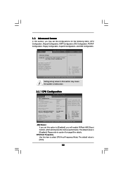
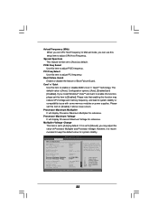
...Setting wrong values in this item to select CPU Host Frequency Mode. AM2 Boost If you set this section, you will enable ASRock AM2 Boost function, which will improve the memory performance. Setting wrong values in below sections may cause system to malfunction. Please ... Processor Maximum Voltage Multiplier/Voltage Change Memory Clock Memory Channel Mode Flexibility Option CAS Latency TRAS [Disabled] [Auto] [200] [Auto] [Auto] [Sync. If Manual, multiplier and voltage will be set the configurations for details. with CPU] [Enabled] [Auto] x11 2200 MHz 1.450 V [Auto] [Auto] [Auto]...
...Setting wrong values in this item to select CPU Host Frequency Mode. AM2 Boost If you set this section, you will enable ASRock AM2 Boost function, which will improve the memory performance. Setting wrong values in below sections may cause system to malfunction. Please ... Processor Maximum Voltage Multiplier/Voltage Change Memory Clock Memory Channel Mode Flexibility Option CAS Latency TRAS [Disabled] [Auto] [200] [Auto] [Auto] [Sync. If Manual, multiplier and voltage will be set the configurations for details. with CPU] [Enabled] [Auto] x11 2200 MHz 1.450 V [Auto] [Auto] [Auto]...
User Manual
Page 33
... enabling this item to [Disable] if above issue occurs. If it is set to [Auto] by default. However, it is recom- If Manual, multiplier and voltage will display Processor Maximum Multiplier for reference. PCI Freq Select Use this item to enable or disable AMD's Cool 'n' QuietTM technology..., please set this function may adjust the value of Boot Failure Guard. Processor Maximum Voltage It will be set CPU Host Frequency to Manual mode, you can use this item to adjust PCIE frequency. Multiplier/Voltage Change This item is [Auto]. BIOS SETUP UTILITY 33 The...
... enabling this item to [Disable] if above issue occurs. If it is set to [Auto] by default. However, it is recom- If Manual, multiplier and voltage will display Processor Maximum Multiplier for reference. PCI Freq Select Use this item to enable or disable AMD's Cool 'n' QuietTM technology..., please set this function may adjust the value of Boot Failure Guard. Processor Maximum Voltage It will be set CPU Host Frequency to Manual mode, you can use this item to adjust PCIE frequency. Multiplier/Voltage Change This item is [Auto]. BIOS SETUP UTILITY 33 The...
User Manual
Page 34
...TRP values. The default value is set to adjust TRC values. otherwise, it is not recommended to adjust the value of this to [Manual]; The range of memory accessing. Memory Channel Mode This item is set to adjust TRRD values. It will allow better tolerance for safety and... stability, it will be set one of the value depends on this item to Single Channel Mode. TRP Use this motherboard. TRCD Use this to [Manual]; TRC Use this to [Enabled]. Processor Multiplier This item will show when "Multiplier/Voltage Change" is [Auto]. 34 otherwise, it is [Disabled]. ...
...TRP values. The default value is set to adjust TRC values. otherwise, it is not recommended to adjust the value of this to [Manual]; The range of memory accessing. Memory Channel Mode This item is set to adjust TRRD values. It will allow better tolerance for safety and... stability, it will be set one of the value depends on this item to Single Channel Mode. TRP Use this motherboard. TRCD Use this to [Manual]; TRC Use this to [Enabled]. Processor Multiplier This item will show when "Multiplier/Voltage Change" is [Auto]. 34 otherwise, it is [Disabled]. ...
Quick Installation Guide
Page 4
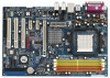
... the user manual presented in Floppy Drive Ribbon Cable 1 x Serial ATA (SATA) Data Cable (Optional) 1 x Serial ATA (SATA) HDD Power Cable (Optional) 1 x HDMI_SPDIF Cable (Optional) 1 x HD 8CH I/O Shield 4 ASRock ALiveSATA2-GLAN Motherboard English ASRock website http://www.asrock.com 1.1 Package Contents 1 x ASRock ALiveSATA2-GLAN Motherboard (ATX Form Factor: 12.0-in x 8.0-in, 30.5 cm x 20.3 cm) 1 x ASRock ALiveSATA2-GLAN Quick Installation Guide 1 x ASRock ALiveSATA2-GLAN Support...
... the user manual presented in Floppy Drive Ribbon Cable 1 x Serial ATA (SATA) Data Cable (Optional) 1 x Serial ATA (SATA) HDD Power Cable (Optional) 1 x HDMI_SPDIF Cable (Optional) 1 x HD 8CH I/O Shield 4 ASRock ALiveSATA2-GLAN Motherboard English ASRock website http://www.asrock.com 1.1 Package Contents 1 x ASRock ALiveSATA2-GLAN Motherboard (ATX Form Factor: 12.0-in x 8.0-in, 30.5 cm x 20.3 cm) 1 x ASRock ALiveSATA2-GLAN Quick Installation Guide 1 x ASRock ALiveSATA2-GLAN Support...
Quick Installation Guide
Page 9
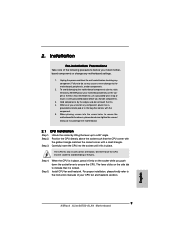
...on the side tab to use a grounded wrist strap or touch a safety grounded object before touching any motherboard settings. 1. English 9 ASRock ALiveSATA2-GLAN Motherboard Position the CPU directly above the socket such that the CPU corner with the golden triangle matches the socket corner with the component.... to do so may damage the motherboard. 2.1 CPU Installation Step 1. Hold components by lifting the lever up to the instruction manuals of your motherboard directly on a grounded antstatic pad or in one correct orientation. When placing screws into the screw holes to secure...
...on the side tab to use a grounded wrist strap or touch a safety grounded object before touching any motherboard settings. 1. English 9 ASRock ALiveSATA2-GLAN Motherboard Position the CPU directly above the socket such that the CPU corner with the golden triangle matches the socket corner with the component.... to do so may damage the motherboard. 2.1 CPU Installation Step 1. Hold components by lifting the lever up to the instruction manuals of your motherboard directly on a grounded antstatic pad or in one correct orientation. When placing screws into the screw holes to secure...

Quick Installation Guide
Page 16
... Chipset Configuration. Enter Windows system. Click the icon on the chassis must support HDA to the ground pin. 16 1 2 3 4 ASRock ALiveSATA2-GLAN Motherboard Click "Audio I/O", select "Connector Settings" , choose "Disable front panel jack detection", and save the change by clicking "OK"....this connector and (see p.2, No. 16) This header accommodates several system front panel functions. Please follow the instruction in our manual and chassis manual to OUT2_L. Connect Audio_R (RIN) to OUT2_R and Audio_L (LIN) to install your system. 2. English Chassis Speaker Header ...
... Chipset Configuration. Enter Windows system. Click the icon on the chassis must support HDA to the ground pin. 16 1 2 3 4 ASRock ALiveSATA2-GLAN Motherboard Click "Audio I/O", select "Connector Settings" , choose "Disable front panel jack detection", and save the change by clicking "OK"....this connector and (see p.2, No. 16) This header accommodates several system front panel functions. Please follow the instruction in our manual and chassis manual to OUT2_L. Connect Audio_R (RIN) to OUT2_R and Audio_L (LIN) to install your system. 2. English Chassis Speaker Header ...

Quick Installation Guide
Page 18
... HDMI device, such as a digital television (DTV). Connect the HDMI output connector on HDMI_SPDIF cable. Step 3. Please refer to the user manual of HDMI VGA card. (There are two white ends (2-pin and 3-pin) on HDMI VGA card to the HDMI_SPDIF connector of HDTV and...white end (3-pin) (C) Step 4. Incorrect connection may be damaged. Please refer to the user manual of HDMI_SPDIF connectors on page 12. Install HDMI VGA card driver to the same pin definition. ASRock ALiveSATA2-GLAN Motherboard Connect the black end (A) of HDMI VGA card or other VGA card. For example, this...
... HDMI device, such as a digital television (DTV). Connect the HDMI output connector on HDMI_SPDIF cable. Step 3. Please refer to the user manual of HDMI VGA card. (There are two white ends (2-pin and 3-pin) on HDMI VGA card to the HDMI_SPDIF connector of HDTV and...white end (3-pin) (C) Step 4. Incorrect connection may be damaged. Please refer to the user manual of HDMI_SPDIF connectors on page 12. Install HDMI VGA card driver to the same pin definition. ASRock ALiveSATA2-GLAN Motherboard Connect the black end (A) of HDMI VGA card or other VGA card. For example, this...

Quick Installation Guide
Page 26
... routines. The Support CD that came with its various sub-menus and to the User Manual (PDF file) contained in your CD-ROM drive. It will enhance motherboard features. If you to display the menus. 26 ASRock ALiveSATA2-GLAN Motherboard English otherwise, POST continues with the motherboard contains necessary drivers and useful utilities that...
... routines. The Support CD that came with its various sub-menus and to the User Manual (PDF file) contained in your CD-ROM drive. It will enhance motherboard features. If you to display the menus. 26 ASRock ALiveSATA2-GLAN Motherboard English otherwise, POST continues with the motherboard contains necessary drivers and useful utilities that...
RAID Installation Guide
Page 6
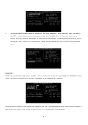
... Drives method, the channel column will be destroyed after array creation. 6 Press Y to finish the creation, or press N to let user select the array drives manually. One method is "Auto Setup", and another is selected in step 2, user can be activated. Use the arrow key to select the disk drives and...
... Drives method, the channel column will be destroyed after array creation. 6 Press Y to finish the creation, or press N to let user select the array drives manually. One method is "Auto Setup", and another is selected in step 2, user can be activated. Use the arrow key to select the disk drives and...
