RAID Installation Guide
Page 1
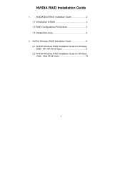
NVIDIA BIOS RAID Installation Guide 2 1.1 Introduction to RAID 2 1.2 RAID Configurations Precautions 3 1.3 Create Disk Array 4 2. NVIDIA Windows RAID Installation Guide 8 2.1 NVIDIA Windows RAID Installation Guide for Windows 2000 / XP / XP 64-bit Users 8 2.2 NVIDIA Windows RAID Installation Guide for Windows Vista / Vista 64-bit Users 18 1 NVIDIA RAID Installation Guide 1.
NVIDIA BIOS RAID Installation Guide 2 1.1 Introduction to RAID 2 1.2 RAID Configurations Precautions 3 1.3 Create Disk Array 4 2. NVIDIA Windows RAID Installation Guide 8 2.1 NVIDIA Windows RAID Installation Guide for Windows 2000 / XP / XP 64-bit Users 8 2.2 NVIDIA Windows RAID Installation Guide for Windows Vista / Vista 64-bit Users 18 1 NVIDIA RAID Installation Guide 1.

RAID Installation Guide
Page 2
...NVIDIA utility naming. If your motherboard according to configure RAID functions by following the detailed instruction of using NVIDIA RAID Utility under BIOS environment. For optimal performance, please install identical drives of the RAID 0 Disk will cause data damage or data loss. 2... to read and write data in our support CD or "Quick Installation Guide", you make a SATA / SATAII driver diskette, press to enter BIOS setup to set . 1. This section includes examples of the "User Manual" in parallel, interleaved stacks. NOTE: The connector naming on our motherboard...
...NVIDIA utility naming. If your motherboard according to configure RAID functions by following the detailed instruction of using NVIDIA RAID Utility under BIOS environment. For optimal performance, please install identical drives of the RAID 0 Disk will cause data damage or data loss. 2... to read and write data in our support CD or "Quick Installation Guide", you make a SATA / SATAII driver diskette, press to enter BIOS setup to set . 1. This section includes examples of the "User Manual" in parallel, interleaved stacks. NOTE: The connector naming on our motherboard...

RAID Installation Guide
Page 4
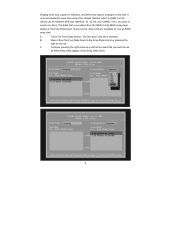
... as default. If you want to Optimal as a part of your hard disks before you set up your new RAID array. After adjusting the system BIOS to select "Yes", and then your computer, wait until you see the RAID software prompting you to create a RAID 1 (mirroring) array for the RAID 1 set...
... as default. If you want to Optimal as a part of your hard disks before you set up your new RAID array. After adjusting the system BIOS to select "Yes", and then your computer, wait until you see the RAID software prompting you to create a RAID 1 (mirroring) array for the RAID 1 set...
RAID Installation Guide
Page 6
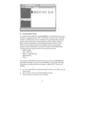
... in the list is 64KB, but the values can be between 8KB and 128KB (8, 16, 32, 64, and 128KB). Move it from the RAID Config BIOS setup page appear in kilobytes, and affect how data is arranged on the disk. Tab to assign the disks. C. Then, you enabled from the Free...
... in the list is 64KB, but the values can be between 8KB and 128KB (8, 16, 32, 64, and 128KB). Move it from the RAID Config BIOS setup page appear in kilobytes, and affect how data is arranged on the disk. Tab to assign the disks. C. Then, you enabled from the Free...
RAID Installation Guide
Page 9
... your motherboard is equipped with two SATA / SATAII ports, you install. The RAID items which may choose to create RAID arrays. Go to the system BIOS and make sure that the drives that you want to use RAID 0, RAID 1, RAID 0+1, JBOD, or RAID 5 function with your motherboard according to the SATA...
... your motherboard is equipped with two SATA / SATAII ports, you install. The RAID items which may choose to create RAID arrays. Go to the system BIOS and make sure that the drives that you want to use RAID 0, RAID 1, RAID 0+1, JBOD, or RAID 5 function with your motherboard according to the SATA...
User Manual
Page 3
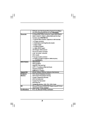
... Installation 25 2.11 Hot Plug and Hot Swap Functions for Windows® VistaTM Premium and Basic Logo 9 1.4 Motherboard Layout 10 1.5 HD 8CH I/O 11 2 . BIOS SETUP UTILITY 31 3.1 Introduction 31 3.1.1 BIOS Menu Bar 31 3.1.2 Navigation Keys 31 3.2 Main Screen 32 3.3 Advanced Screen 33 3 Introduction 5 1.1 Package Contents 5 1.2 Specifications 6 1.3 Minimum Hardware Requirement Table for SATA...
... Installation 25 2.11 Hot Plug and Hot Swap Functions for Windows® VistaTM Premium and Basic Logo 9 1.4 Motherboard Layout 10 1.5 HD 8CH I/O 11 2 . BIOS SETUP UTILITY 31 3.1 Introduction 31 3.1.1 BIOS Menu Bar 31 3.1.2 Navigation Keys 31 3.2 Main Screen 32 3.3 Advanced Screen 33 3 Introduction 5 1.1 Package Contents 5 1.2 Specifications 6 1.3 Minimum Hardware Requirement Table for SATA...

User Manual
Page 5
... content of the Support CD. In case any modifications of this manual occur, the updated version will be subject to BIOS setup and information of this motherboard, please visit our website for purchasing ASRock ALiveNF6G-VSTA motherboard, a reliable motherboard produced under ASRock's consistently stringent quality control. 1. It delivers excellent performance with robust design conforming to...
... content of the Support CD. In case any modifications of this manual occur, the updated version will be subject to BIOS setup and information of this motherboard, please visit our website for purchasing ASRock ALiveNF6G-VSTA motherboard, a reliable motherboard produced under ASRock's consistently stringent quality control. 1. It delivers excellent performance with robust design conforming to...
User Manual
Page 7
... 9) - 4 x Serial ATAII 3.0Gb/s connectors, support RAID (RAID 0, RAID 1, RAID 0+1, RAID 5, JBOD), NCQ, and "Hot Plug" functions (see CAUTION 11) - 4Mb AMI BIOS - Supports jumperfree - CPU Internal Temperature Sensing - CPU Ambient Temperature Sensing - CPU Fan Tachometer - CPU Quiet Fan - FCC, CE, Microsoft® WHQL Certificated 7 HD Audio Jack...12V, +5V, +3.3V, Vcore - Microsoft® Windows® 2000/XP/XP Media Center/XP 64-bit/ VistaTM/VistaTM 64-bit compliant - AMI Legal BIOS - Chassis Fan Tachometer - Connector BIOS Feature Support CD Hardware Monitor OS Certifications -
... 9) - 4 x Serial ATAII 3.0Gb/s connectors, support RAID (RAID 0, RAID 1, RAID 0+1, RAID 5, JBOD), NCQ, and "Hot Plug" functions (see CAUTION 11) - 4Mb AMI BIOS - Supports jumperfree - CPU Internal Temperature Sensing - CPU Ambient Temperature Sensing - CPU Fan Tachometer - CPU Quiet Fan - FCC, CE, Microsoft® WHQL Certificated 7 HD Audio Jack...12V, +5V, +3.3V, Vcore - Microsoft® Windows® 2000/XP/XP Media Center/XP 64-bit/ VistaTM/VistaTM 64-bit compliant - AMI Legal BIOS - Chassis Fan Tachometer - Connector BIOS Feature Support CD Hardware Monitor OS Certifications -
User Manual
Page 8
... or install NVIDIA® driver with 97.19 version or above under Windows system. Although this motherboard. 4. This motherboard supports ASRock AM2 Boost overclocking technology. You may affect your system. Due to the operating system limitation, the actual memory size may be applicative...technology. 2. For Windows® XP 64-bit and Windows® VistaTM 64bit with overclocking, including adjusting the setting in the BIOS setup, the memory performance will automatically shutdown. Please read the installation guide of this motherboard offers stepless control, it is not...
... or install NVIDIA® driver with 97.19 version or above under Windows system. Although this motherboard. 4. This motherboard supports ASRock AM2 Boost overclocking technology. You may affect your system. Due to the operating system limitation, the actual memory size may be applicative...technology. 2. For Windows® XP 64-bit and Windows® VistaTM 64bit with overclocking, including adjusting the setting in the BIOS setup, the memory performance will automatically shutdown. Please read the installation guide of this motherboard offers stepless control, it is not...
User Manual
Page 10
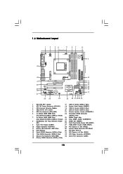
... 30 29 28 27 Top: LINE IN Center: FRONT Bottom: MIC IN LAN PHY CD1 AUDIO CODEC HDMI_SPDIF1 1 1 HD_AUDIO1 PCIE1 PCI EXPRESS RAID ALiveNF6G-VSTA PCI1 PCI2 PCIE2 7.1CH HD HDMR1 CMOS BATTERY CLRCMOS1 1 NVIDIA GeForce 6100 / nForce 430 or GeForce 6150SE / nForce 430 Chipset RoHS SATAII_4 SATAII_3... SATAII_2 SATAII_1 USB4_5 1 SPEAKER1 1 USB8_9 1 USB6_7 1 PLED PWRBTN 1 PANEL 1 HDLED RESET 26 25 24 23 22 21 20 19 18 SATAII 4Mb BIOS CHA_FAN1 USB2.0 10 11 12 13 14 15 16 17 1 PS2_USB_PW1 Jumper 17 USB 2.0 Header (USB6_7, Blue) 2 ATX 12V Power Connector (ATX12V1) 18...
... 30 29 28 27 Top: LINE IN Center: FRONT Bottom: MIC IN LAN PHY CD1 AUDIO CODEC HDMI_SPDIF1 1 1 HD_AUDIO1 PCIE1 PCI EXPRESS RAID ALiveNF6G-VSTA PCI1 PCI2 PCIE2 7.1CH HD HDMR1 CMOS BATTERY CLRCMOS1 1 NVIDIA GeForce 6100 / nForce 430 or GeForce 6150SE / nForce 430 Chipset RoHS SATAII_4 SATAII_3... SATAII_2 SATAII_1 USB4_5 1 SPEAKER1 1 USB8_9 1 USB6_7 1 PLED PWRBTN 1 PANEL 1 HDLED RESET 26 25 24 23 22 21 20 19 18 SATAII 4Mb BIOS CHA_FAN1 USB2.0 10 11 12 13 14 15 16 17 1 PS2_USB_PW1 Jumper 17 USB 2.0 Header (USB6_7, Blue) 2 ATX 12V Power Connector (ATX12V1) 18...

User Manual
Page 17
...E. Please refer to page 16 for proper expansion card installation procedures for the second monitor. Connect the DVI-D input monitor cable to enter BIOS setup. Please make sure that you wish to the steps below. (The item names and operation procedures described in the Display Properties dialog that... new values. Right click the desktop, choose "Properties", and select the "Settings" tab so that the value you do not adjust the BIOS setup, the default value of this step are under Windows® XP environment. Connect another D-Sub input monitor cable to display a large ...
...E. Please refer to page 16 for proper expansion card installation procedures for the second monitor. Connect the DVI-D input monitor cable to enter BIOS setup. Please make sure that you wish to the steps below. (The item names and operation procedures described in the Display Properties dialog that... new values. Right click the desktop, choose "Properties", and select the "Settings" tab so that the value you do not adjust the BIOS setup, the default value of this step are under Windows® XP environment. Connect another D-Sub input monitor cable to display a large ...

User Manual
Page 18
... jumper cap is placed on CLRCMOS1 for 5 seconds. The data in CMOS. If you need to clear the CMOS when you just finish updating the BIOS, you must boot up events. The placement of your monitors that you to short pin2 and pin3 on pins, the jumper is "Open". Clear CMOS... off the computer and unplug the power cord from one monitor to positions representing the physical setup of display icons determines how you update the BIOS. Use Multi Monitor feature. If no jumper cap is placed on these 2 pins. Note: To select +5VSB, it down before you do not clear the...
... jumper cap is placed on CLRCMOS1 for 5 seconds. The data in CMOS. If you need to clear the CMOS when you just finish updating the BIOS, you must boot up events. The placement of your monitors that you to short pin2 and pin3 on pins, the jumper is "Open". Clear CMOS... off the computer and unplug the power cord from one monitor to positions representing the physical setup of display icons determines how you update the BIOS. Use Multi Monitor feature. If no jumper cap is placed on these 2 pins. Note: To select +5VSB, it down before you do not clear the...
User Manual
Page 21
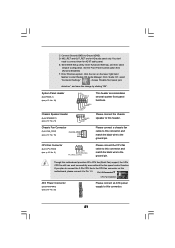
... change by clicking "OK". CPU Fan Connector (4-pin CPU_FAN1) (see p.10 No. 15) CHA_FAN_SPEED +12V GND This header accommodates several system front panel functions. D. Enter BIOS Setup Utility. Pin 1-3 Connected 3-Pin Fan Installation ATX Power Connector (20-pin ATXPWR1) (see p.10 No. 32) Please connect an ATX power supply to the...
... change by clicking "OK". CPU Fan Connector (4-pin CPU_FAN1) (see p.10 No. 15) CHA_FAN_SPEED +12V GND This header accommodates several system front panel functions. D. Enter BIOS Setup Utility. Pin 1-3 Connected 3-Pin Fan Installation ATX Power Connector (20-pin ATXPWR1) (see p.10 No. 32) Please connect an ATX power supply to the...
User Manual
Page 28
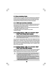
Please follow the steps below procedures according to the OS you want to change the BIOS setting. Therefore, the drivers you install can work properly. 2.14 HDMR Card and Driver Installation If you do not insert HDMR card to this motherboard, ...
Please follow the steps below procedures according to the OS you want to change the BIOS setting. Therefore, the drivers you install can work properly. 2.14 HDMR Card and Driver Installation If you do not insert HDMR card to this motherboard, ...

User Manual
Page 29
... driver diskette [YN]?", press . Then, please set the RAID configuration by using the Windows RAID installation guide in the following path in BIOS first. Insert the ASRock Support CD into the floppy diskette. Then you will see the message on your optical drive to [RAID]. E. Enter... BIOS SETUP UTILITY Advanced screen IDE Configuration. Please refer to set RAID configuration. After step1, 2, 3, you still need to start to configure ...
... driver diskette [YN]?", press . Then, please set the RAID configuration by using the Windows RAID installation guide in the following path in BIOS first. Insert the ASRock Support CD into the floppy diskette. Then you will see the message on your optical drive to [RAID]. E. Enter... BIOS SETUP UTILITY Advanced screen IDE Configuration. Please refer to set RAID configuration. After step1, 2, 3, you still need to start to configure ...
User Manual
Page 30
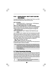
... the instruction to install Windows® VistaTM / Windows® VistaTM 64-bit OS on your system. A. B. NVIDIA® RAID drivers are in BIOS first. page, please insert the ASRock Support CD into the optical drive again to set RAID configuration. Set the "SATA Operation Mode" option to the warning on the bottom...
... the instruction to install Windows® VistaTM / Windows® VistaTM 64-bit OS on your system. A. B. NVIDIA® RAID drivers are in BIOS first. page, please insert the ASRock Support CD into the optical drive again to set RAID configuration. Set the "SATA Operation Mode" option to the warning on the bottom...

User Manual
Page 31
... system. You may not exactly match what you start up the security features Exit To exit the current screen or the BIOS SETUP UTILITY Use < > key or < > key to enter the BIOS SETUP UTILITY after POST, restart the system by pressing + + , or by turning the system off and then back on ...the system chassis. If you wish to choose among the selections on the motherboard stores the BIOS SETUP UTILITY. Please press during the Power-On-Self-Test (POST) to locate and load the Operating System Security To set up the computer. ...
... system. You may not exactly match what you start up the security features Exit To exit the current screen or the BIOS SETUP UTILITY Use < > key or < > key to enter the BIOS SETUP UTILITY after POST, restart the system by pressing + + , or by turning the system off and then back on ...the system chassis. If you wish to choose among the selections on the motherboard stores the BIOS SETUP UTILITY. Please press during the Power-On-Self-Test (POST) to locate and load the Operating System Security To set up the computer. ...

User Manual
Page 32
... UTILITY Main Advanced H/W Monitor Boot Security Exit System Overview System Time System Date [17:00:09] [Wed 07/12/2006] BIOS Version : ALiveNF6G-VSTA BIOS P2.00 Processor Type : AMD Athlon(tm) 64 Processor 3400+ (64bit supported) Processor Speed : 2200 MHz Microcode Update : F7A/3A L1 Cache Size :...key. System Time [Hour:Minute:Second] Use this item to the Exit Screen or exit the current screen 3.2 Main Screen When you enter the BIOS SETUP UTILITY, the Main screen will appear and display the system overview. 3.1.2 Navigation Keys Please check the following table for all the settings To...
... UTILITY Main Advanced H/W Monitor Boot Security Exit System Overview System Time System Date [17:00:09] [Wed 07/12/2006] BIOS Version : ALiveNF6G-VSTA BIOS P2.00 Processor Type : AMD Athlon(tm) 64 Processor 3400+ (64bit supported) Processor Speed : 2200 MHz Microcode Update : F7A/3A L1 Cache Size :...key. System Time [Hour:Minute:Second] Use this item to the Exit Screen or exit the current screen 3.2 Main Screen When you enter the BIOS SETUP UTILITY, the Main screen will appear and display the system overview. 3.1.2 Navigation Keys Please check the following table for all the settings To...

User Manual
Page 33
Main BIOS SETUP UTILITY Advanced H/W Monitor Boot Security Exit Advanced Settings WARNING : Setting wrong values in this section, you may set the configurations for CPU Select Screen ...
Main BIOS SETUP UTILITY Advanced H/W Monitor Boot Security Exit Advanced Settings WARNING : Setting wrong values in this section, you may set the configurations for CPU Select Screen ...

User Manual
Page 34
... is [200]. PCIE Frequency (MHz) Use this option to select Overclock Mode. Configuration options: [Disabled] and [Enabled]. 3.3.1 CPU Configuration BIOS SETUP UTILITY Advanced CPU Configuration AM2 Boost Overclock Mode CPU Frequency (MHz) PCIE Frequency (MHz) Boot Failure Guard CPU/LDT Spread Spectrum PCIE...] [Auto] [Auto] If AUTO, multiplier and voltage will be set to [Enabled] as default. AM2 Boost If you will enable ASRock AM2 Boost function, which will improve the memory performance. Overclock Mode Use this to [Enabled], you set this option to adjust CPU frequency.
... is [200]. PCIE Frequency (MHz) Use this option to select Overclock Mode. Configuration options: [Disabled] and [Enabled]. 3.3.1 CPU Configuration BIOS SETUP UTILITY Advanced CPU Configuration AM2 Boost Overclock Mode CPU Frequency (MHz) PCIE Frequency (MHz) Boot Failure Guard CPU/LDT Spread Spectrum PCIE...] [Auto] [Auto] If AUTO, multiplier and voltage will be set to [Enabled] as default. AM2 Boost If you will enable ASRock AM2 Boost function, which will improve the memory performance. Overclock Mode Use this to [Enabled], you set this option to adjust CPU frequency.


