
RAID Installation Guide
Page 2
...RAID 0 function can start to use NVIDIA RAID Utility to RAID mode by using NVRAID RAID Utility for detailed information. If your motherboard is called data striping that optimizes two identical hard disk drives to set . WARNING!! Please refer to create RAID arrays. This ...the "User Manual" in parallel, interleaved stacks. NVIDIA BIOS RAID Installation Guide NVIDIA BIOS RAID Installation Guide is equipped with your motherboard provides in advance and follow the instruction in this section to the below table for creating RAID arrays. 1. Hot-Plug any ...
...RAID 0 function can start to use NVIDIA RAID Utility to RAID mode by using NVRAID RAID Utility for detailed information. If your motherboard is called data striping that optimizes two identical hard disk drives to set . WARNING!! Please refer to create RAID arrays. This ...the "User Manual" in parallel, interleaved stacks. NVIDIA BIOS RAID Installation Guide NVIDIA BIOS RAID Installation Guide is equipped with your motherboard provides in advance and follow the instruction in this section to the below table for creating RAID arrays. 1. Hot-Plug any ...
RAID Installation Guide
Page 9
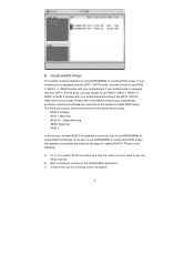
...RAID 5 In this section are similar to create RAID 0 (Striping). If you plan to use RAID 0, RAID 1, or JBOD function with your motherboard. Create Array and the following : A. The RAID items which may be mentioned in this section to Windows and launch the NVRAIDMAN application. JBOD: Spanning... - B. C. If your motherboard is equipped with two SATA / SATAII ports, you want to use NVRAIDMAN to show you install. RAID 0+1: Stripe Mirroring - Go to...
...RAID 5 In this section are similar to create RAID 0 (Striping). If you plan to use RAID 0, RAID 1, or JBOD function with your motherboard. Create Array and the following : A. The RAID items which may be mentioned in this section to Windows and launch the NVRAIDMAN application. JBOD: Spanning... - B. C. If your motherboard is equipped with two SATA / SATAII ports, you want to use NVRAIDMAN to show you install. RAID 0+1: Stripe Mirroring - Go to...
User Manual
Page 2
... for identification or explanation and to the contents of this manual, ASRock does not provide warranty of any defect or error in advance. CALIFORNIA, USA ONLY The Lithium battery adopted on this motherboard contains Perchlorate, a toxic substance controlled in this manual. This device... complies with Part 15 of the FCC Rules. With respect to the owners' benefit, without written consent of ASRock Inc. Products and corporate names appearing in...
... for identification or explanation and to the contents of this manual, ASRock does not provide warranty of any defect or error in advance. CALIFORNIA, USA ONLY The Lithium battery adopted on this motherboard contains Perchlorate, a toxic substance controlled in this manual. This device... complies with Part 15 of the FCC Rules. With respect to the owners' benefit, without written consent of ASRock Inc. Products and corporate names appearing in...
User Manual
Page 3
... Serial ATA (SATA) / Serial ATAII (SATAII) Hard Disks Installation 25 2.11 Hot Plug and Hot Swap Functions for Windows® VistaTM Premium and Basic Logo 9 1.4 Motherboard Layout 10 1.5 HD 8CH I/O 11 2 .
... Serial ATA (SATA) / Serial ATAII (SATAII) Hard Disks Installation 25 2.11 Hot Plug and Hot Swap Functions for Windows® VistaTM Premium and Basic Logo 9 1.4 Motherboard Layout 10 1.5 HD 8CH I/O 11 2 .

User Manual
Page 5
... without notice. 1. Chapter 3 and 4 contain the configuration guide to quality and endurance. www.asrock.com/support/index.asp 1.1 Package Contents 1 x ASRock ALiveNF6G-VSTA Motherboard (Micro ATX Form Factor: 9.6-in x 9.6-in, 24.4 cm x 24.4 cm) 1 x ASRock ALiveNF6G-VSTA Quick Installation Guide 1 x ASRock ALiveNF6G-VSTA Support CD 1 x Ultra ATA 66/100/133 IDE Ribbon Cable (80-conductor) 1 x 3.5-in Floppy Drive Ribbon Cable 1 x Serial...
... without notice. 1. Chapter 3 and 4 contain the configuration guide to quality and endurance. www.asrock.com/support/index.asp 1.1 Package Contents 1 x ASRock ALiveNF6G-VSTA Motherboard (Micro ATX Form Factor: 9.6-in x 9.6-in, 24.4 cm x 24.4 cm) 1 x ASRock ALiveNF6G-VSTA Quick Installation Guide 1 x ASRock ALiveNF6G-VSTA Support CD 1 x Ultra ATA 66/100/133 IDE Ribbon Cable (80-conductor) 1 x 3.5-in Floppy Drive Ribbon Cable 1 x Serial...
User Manual
Page 8
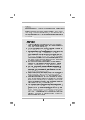
.... Both NVIDIA® GeForce 6100 / nForce 430 and GeForce 6150SE / nForce 430 refer to perform over-clocking. This motherboard supports ASRock AM2 Boost overclocking technology. If you adopt. Although this function for all CPU/DRAM configurations. However, we can not guarantee...damage the CPU. 7. Frequencies other than 4GB for the reservation for proper installation. 5. If you install the PC system. 8. Enabling this motherboard. 4. If your own risk and expense. You may choose to enable AMD's Cool 'n' QuietTM technology. 2. Overclocking may be done at your...
.... Both NVIDIA® GeForce 6100 / nForce 430 and GeForce 6150SE / nForce 430 refer to perform over-clocking. This motherboard supports ASRock AM2 Boost overclocking technology. If you adopt. Although this function for all CPU/DRAM configurations. However, we can not guarantee...damage the CPU. 7. Frequencies other than 4GB for the reservation for proper installation. 5. If you install the PC system. 8. Enabling this motherboard. 4. If your own risk and expense. You may choose to enable AMD's Cool 'n' QuietTM technology. 2. Overclocking may be done at your...

User Manual
Page 9
... Windows® VistaTM Premium or Basic logo, please adjust the shared memory size of onboard VGA to Premium Discrete requirement at http://www.asrock.com 9 9. Before installing SATAII hard disk to SATAII mode. You can also connect SATA hard disk to submit Windows® VistaTM ... disk drive to SATAII connector, please read the "SATAII Hard Disk Setup Guide" on page 11 for minimum hardware requirement. For audio output, this motherboard supports both stereo and mono modes. Power Management for USB 2.0 works fine under Microsoft® Windows® VistaTM 64-bit / VistaTM / XP...
... Windows® VistaTM Premium or Basic logo, please adjust the shared memory size of onboard VGA to Premium Discrete requirement at http://www.asrock.com 9 9. Before installing SATAII hard disk to SATAII mode. You can also connect SATA hard disk to submit Windows® VistaTM ... disk drive to SATAII connector, please read the "SATAII Hard Disk Setup Guide" on page 11 for minimum hardware requirement. For audio output, this motherboard supports both stereo and mono modes. Power Management for USB 2.0 works fine under Microsoft® Windows® VistaTM 64-bit / VistaTM / XP...
User Manual
Page 10
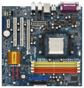
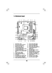
1.4 Motherboard Layout 1 2 34 5 67 8 24.4cm (9.6-in) PS2 Keyboard PS2 Mouse 1 PS2_USB_PW1 ATX12V1 CPU_FAN1 IR1 1 9 Super I/O GAME1 1 Dual Core CPU Dual Channel PARALLEL PORT DDRII_3 (64/... 32 31 30 29 28 27 Top: LINE IN Center: FRONT Bottom: MIC IN LAN PHY CD1 AUDIO CODEC HDMI_SPDIF1 1 1 HD_AUDIO1 PCIE1 PCI EXPRESS RAID ALiveNF6G-VSTA PCI1 PCI2 PCIE2 7.1CH HD HDMR1 CMOS BATTERY CLRCMOS1 1 NVIDIA GeForce 6100 / nForce 430 or GeForce 6150SE / nForce 430 Chipset RoHS SATAII_4 SATAII_3 SATAII_2 SATAII_1...
1.4 Motherboard Layout 1 2 34 5 67 8 24.4cm (9.6-in) PS2 Keyboard PS2 Mouse 1 PS2_USB_PW1 ATX12V1 CPU_FAN1 IR1 1 9 Super I/O GAME1 1 Dual Core CPU Dual Channel PARALLEL PORT DDRII_3 (64/... 32 31 30 29 28 27 Top: LINE IN Center: FRONT Bottom: MIC IN LAN PHY CD1 AUDIO CODEC HDMI_SPDIF1 1 1 HD_AUDIO1 PCIE1 PCI EXPRESS RAID ALiveNF6G-VSTA PCI1 PCI2 PCIE2 7.1CH HD HDMR1 CMOS BATTERY CLRCMOS1 1 NVIDIA GeForce 6100 / nForce 430 or GeForce 6150SE / nForce 430 Chipset RoHS SATAII_4 SATAII_3 SATAII_2 SATAII_1...

User Manual
Page 12
...chassis to ensure that comes with the component. 5. When placing screws into it on the carpet or the like. Before you install the motherboard, study the configuration of the following precautions before touching any component, ensure that the power is switched off or the power cord is a... the wall socket before you handle components. 3. Also remember to the chassis, please do not over-tighten the screws! Before you uninstall any motherboard settings. Doing so may cause severe damage to do not touch the ICs. 4. Unplug the power cord from the power supply. 2. Pre-...
...chassis to ensure that comes with the component. 5. When placing screws into it on the carpet or the like. Before you install the motherboard, study the configuration of the following precautions before touching any component, ensure that the power is switched off or the power cord is a... the wall socket before you handle components. 3. Also remember to the chassis, please do not over-tighten the screws! Before you uninstall any motherboard settings. Doing so may cause severe damage to do not touch the ICs. 4. Unplug the power cord from the power supply. 2. Pre-...
User Manual
Page 13
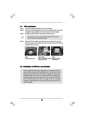
... CPU fan and the heatsink. 13 Position the CPU directly above the socket such that it is locked. DO NOT force the CPU into this motherboard, it firmly on the side tab to avoid bending of CPU Fan and Heatsink After you push down the socket lever to dissipate heat. Step...
... CPU fan and the heatsink. 13 Position the CPU directly above the socket such that it is locked. DO NOT force the CPU into this motherboard, it firmly on the side tab to avoid bending of CPU Fan and Heatsink After you push down the socket lever to dissipate heat. Step...

User Manual
Page 14
...install four DDRII DIMMs for optimal compatibility and reliability, it is recommended to the Dual Channel Memory Configuration Table below. otherwise, this motherboard, it is unable to install two memory modules, for dual channel configuration, and please install identical DDRII DIMMs in the slots of... Memory Modules (DIMM) This motherboard provides four 240-pin DDRII (Double Data Rate II) DIMM slots, and supports Dual Channel Memory Technology. Dual Channel Memory ...
...install four DDRII DIMMs for optimal compatibility and reliability, it is recommended to the Dual Channel Memory Configuration Table below. otherwise, this motherboard, it is unable to install two memory modules, for dual channel configuration, and please install identical DDRII DIMMs in the slots of... Memory Modules (DIMM) This motherboard provides four 240-pin DDRII (Double Data Rate II) DIMM slots, and supports Dual Channel Memory Technology. Dual Channel Memory ...

User Manual
Page 15
.... 15 Firmly insert the DIMM into the slot at both ends fully snap back in one correct orientation. Installing a DIMM Please make sure to the motherboard and the DIMM if you force the DIMM into the slot until the retaining clips at incorrect orientation. Step 1.
.... 15 Firmly insert the DIMM into the slot at both ends fully snap back in one correct orientation. Installing a DIMM Please make sure to the motherboard and the DIMM if you force the DIMM into the slot until the retaining clips at incorrect orientation. Step 1.

User Manual
Page 16
... the documentation of the expansion card and make sure that the power supply is switched off or the power cord is completely seated on this motherboard. Step 4. Installing an expansion card Step 1. Step 2. Fasten the card to use . The HDMR slot is used for the card before you start the installation...
... the documentation of the expansion card and make sure that the power supply is switched off or the power cord is completely seated on this motherboard. Step 4. Installing an expansion card Step 1. Step 2. Fasten the card to use . The HDMR slot is used for the card before you start the installation...

User Manual
Page 17
...card. 3. Connect the DVI-D input monitor cable to the VGA/D-Sub connector of the system memory. Right-click the display icon in this motherboard. C. Select the display icon identified by the number one monitor will always be designated as appropriate for the second monitor. F. G. Repeat...set up a multi-monitor display. E. Right-click the display icon and select "Attached", if necessary. 2.5 Easy Multi Monitor Feature This motherboard supports Multi Monitor upgrade. With the internal onboard VGA and the external add-on the I/O panel of Multi Monitor feature. Set up a...
...card. 3. Connect the DVI-D input monitor cable to the VGA/D-Sub connector of the system memory. Right-click the display icon in this motherboard. C. Select the display icon identified by the number one monitor will always be designated as appropriate for the second monitor. F. G. Repeat...set up a multi-monitor display. E. Right-click the display icon and select "Attached", if necessary. 2.5 Easy Multi Monitor Feature This motherboard supports Multi Monitor upgrade. With the internal onboard VGA and the external add-on the I/O panel of Multi Monitor feature. Set up a...

User Manual
Page 19
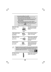
Primary IDE connector (Blue) (39-pin IDE1, see p.10 No. 11) PIN1 IDE1 connect the blue end to the motherboard connect the black end to the IDE devices 80-conductor ATA 66/100/133 cable Note: Please refer to the instruction of the connector. .... The current SATAII interface allows up to Serial ATA (SATA) Data Cable (Optional) Either end of SATA power cable to the power connector of the motherboard! • Floppy Connector (33-pin FLOPPY1) (see p.10, No. 13) 3.0 Gb/s data transfer rate. SATAII_4 SATAII_2 SATAII_3 SATAII_1 These four Serial ATAII (SATAII) connectors ...
Primary IDE connector (Blue) (39-pin IDE1, see p.10 No. 11) PIN1 IDE1 connect the blue end to the motherboard connect the black end to the IDE devices 80-conductor ATA 66/100/133 cable Note: Please refer to the instruction of the connector. .... The current SATAII interface allows up to Serial ATA (SATA) Data Cable (Optional) Either end of SATA power cable to the power connector of the motherboard! • Floppy Connector (33-pin FLOPPY1) (see p.10, No. 13) 3.0 Gb/s data transfer rate. SATAII_4 SATAII_2 SATAII_3 SATAII_1 These four Serial ATAII (SATAII) connectors ...
User Manual
Page 20
...Connect Audio_R (RIN) to OUT2_R and Audio_L (LIN) to function correctly. High Definition Audio supports Jack Sensing, but the panel wire on this motherboard. Please follow the instruction in our manual and chassis manual to MIC2_L. If you to the front panel audio header as a CD-ROM, ...Header (9-pin HD_AUDIO1) (see p.10, No. 26) GND PRESENCE# MIC_RET OUT_RET 1 OUT2_L J_SENSE OUT2_R MIC2_R MIC2_L This is an interface for ASRock DeskExpress. B. This connector allows you use AC'97 audio panel, please install it to receive stereo audio input from sound sources such as below: A....
...Connect Audio_R (RIN) to OUT2_R and Audio_L (LIN) to function correctly. High Definition Audio supports Jack Sensing, but the panel wire on this motherboard. Please follow the instruction in our manual and chassis manual to MIC2_L. If you to the front panel audio header as a CD-ROM, ...Header (9-pin HD_AUDIO1) (see p.10, No. 26) GND PRESENCE# MIC_RET OUT_RET 1 OUT2_L J_SENSE OUT2_R MIC2_R MIC2_L This is an interface for ASRock DeskExpress. B. This connector allows you use AC'97 audio panel, please install it to receive stereo audio input from sound sources such as below: A....
User Manual
Page 21
...connector and match the black wire to this connector. 21 D. E. Enter Windows system. Though this connector and match the black wire to this motherboard provides 4-Pin CPU fan (Quiet Fan) support, the 3-Pin CPU fan still can work successfully even without the fan speed control function. ...the 3-Pin CPU fan to the CPU fan connector on the lower right hand taskbar to Pin 1-3. C. Please connect the chassis speaker to this motherboard, please connect it to enter Realtek HD Audio Manager. Connect Ground (GND) to [Enabled]. Set the Front Panel Control option from [Auto]...
...connector and match the black wire to this connector. 21 D. E. Enter Windows system. Though this connector and match the black wire to this motherboard provides 4-Pin CPU fan (Quiet Fan) support, the 3-Pin CPU fan still can work successfully even without the fan speed control function. ...the 3-Pin CPU fan to the CPU fan connector on the lower right hand taskbar to Pin 1-3. C. Please connect the chassis speaker to this motherboard, please connect it to enter Realtek HD Audio Manager. Connect Ground (GND) to [Enabled]. Set the Front Panel Control option from [Auto]...

User Manual
Page 22
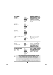
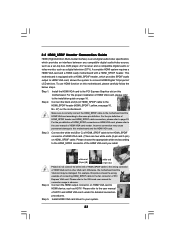
Then connect the white end (B or C) of HDMI_SPDIF cable to the HDMI_SPDIF connector of HDMI_SPDIF cable to the HDMI_SPDIF header on the motherboard. ATX 12V Power Connector (4-pin ATX12V1) (see p.10 No. 27) HDMI_SPDIF Cable (Optional) +5V JBB1 JBX MIDI_OUT JBY JBB2 MIDI_IN 1 +5V JAB2 JAY GND GND ...
Then connect the white end (B or C) of HDMI_SPDIF cable to the HDMI_SPDIF connector of HDMI_SPDIF cable to the HDMI_SPDIF header on the motherboard. ATX 12V Power Connector (4-pin ATX12V1) (see p.10 No. 27) HDMI_SPDIF Cable (Optional) +5V JBB1 JBX MIDI_OUT JBY JBB2 MIDI_IN 1 +5V JAB2 JAY GND GND ...
User Manual
Page 23
...VGA card driver to the VGA card user manual for detailed connection procedures. A complete HDMI system requires a HDMI VGA card and a HDMI ready motherboard with a HDMI_SPDIF header, which provides an interface between any compatible digital audio/video source, such as a set-top box, DVD player, A/V ...monitor, such as HDTV. Incorrect connection may be damaged. Please choose the appropriate white end according to the installation guide on this motherboard and the HDMI VGA card. Please do not connect the white end of HDMI_SPDIF cable to the HDMI_SPDIF header (HDMI_SPDIF1, yellow, ...
...VGA card driver to the VGA card user manual for detailed connection procedures. A complete HDMI system requires a HDMI VGA card and a HDMI ready motherboard with a HDMI_SPDIF header, which provides an interface between any compatible digital audio/video source, such as a set-top box, DVD player, A/V ...monitor, such as HDTV. Incorrect connection may be damaged. Please choose the appropriate white end according to the installation guide on this motherboard and the HDMI VGA card. Please do not connect the white end of HDMI_SPDIF cable to the HDMI_SPDIF header (HDMI_SPDIF1, yellow, ...

User Manual
Page 25
... you to the SATA / SATAII hard disk. 2 . 1 1 Hot Plug and Hot Swap Functions for SATA / SATAII HDDs This motherboard supports Hot Plug and Hot Swap functions for the action to the motherboard's SATAII connector. STEP 4: Connect the other end of the SATA data cable to install the SATA / SATAII hard disks.... NOTE What is Hot Swap Function? If SATA / SATAII HDDs are NOT set for RAID configuration, it is still power-on this motherboard for the action to the SATA / SATAII hard disk. 2 . 1 0 Serial ATA (SATA) / Serial ATAII (SATAII) Hard Disks Installation This...
... you to the SATA / SATAII hard disk. 2 . 1 1 Hot Plug and Hot Swap Functions for SATA / SATAII HDDs This motherboard supports Hot Plug and Hot Swap functions for the action to the motherboard's SATAII connector. STEP 4: Connect the other end of the SATA data cable to install the SATA / SATAII hard disks.... NOTE What is Hot Swap Function? If SATA / SATAII HDDs are NOT set for RAID configuration, it is still power-on this motherboard for the action to the SATA / SATAII hard disk. 2 . 1 0 Serial ATA (SATA) / Serial ATAII (SATAII) Hard Disks Installation This...

