
RAID Installation Guide
Page 2
... two identical hard disk drives to read and write data in this section to configure RAID functions by following the detailed instruction of the "User Manual" in our support CD or "Quick Installation Guide", you can improve the access performance, it will cause data damage or data loss. 2 SATAII_1 (port 1.0) --> Means...
... two identical hard disk drives to read and write data in this section to configure RAID functions by following the detailed instruction of the "User Manual" in our support CD or "Quick Installation Guide", you can improve the access performance, it will cause data damage or data loss. 2 SATAII_1 (port 1.0) --> Means...
User Manual
Page 1
ALiveNF6G-VSTA User Manual Version 1.4 Published October 2007 Copyright©2007 ASRock INC. All rights reserved. 1
ALiveNF6G-VSTA User Manual Version 1.4 Published October 2007 Copyright©2007 ASRock INC. All rights reserved. 1
User Manual
Page 2
... used only for backup purpose, without written consent of ASRock Inc. With respect to the contents of this manual, ASRock does not provide warranty of any kind, either expressed or implied, including but not limited to the implied warranties or conditions of ... the Lithium battery in California, USA, please follow the related regulations in this manual may or may apply, see www.dtsc.ca.gov/hazardouswaste/perchlorate" ASRock Website: http://www.asrock.com 2 Copyright Notice: No part of this manual may be reproduced, transcribed, transmitted, or translated in any language, in any ...
... used only for backup purpose, without written consent of ASRock Inc. With respect to the contents of this manual, ASRock does not provide warranty of any kind, either expressed or implied, including but not limited to the implied warranties or conditions of ... the Lithium battery in California, USA, please follow the related regulations in this manual may or may apply, see www.dtsc.ca.gov/hazardouswaste/perchlorate" ASRock Website: http://www.asrock.com 2 Copyright Notice: No part of this manual may be reproduced, transcribed, transmitted, or translated in any language, in any ...

User Manual
Page 5
...ASRock ALiveNF6G-VSTA motherboard, a reliable motherboard produced under ASRock's consistently stringent quality control. www.asrock.com/support/index.asp 1.1 Package Contents 1 x ASRock ALiveNF6G-VSTA Motherboard (Micro ATX Form Factor: 9.6-in x 9.6-in, 24.4 cm x 24.4 cm) 1 x ASRock ALiveNF6G-VSTA Quick Installation Guide 1 x ASRock ALiveNF6G-VSTA... Shield 1 x COM Port Bracket 5 It delivers excellent performance with robust design conforming to ASRock's commitment to this manual, chapter 1 and 2 contain introduction of the Support CD. You may find the latest VGA cards and ...
...ASRock ALiveNF6G-VSTA motherboard, a reliable motherboard produced under ASRock's consistently stringent quality control. www.asrock.com/support/index.asp 1.1 Package Contents 1 x ASRock ALiveNF6G-VSTA Motherboard (Micro ATX Form Factor: 9.6-in x 9.6-in, 24.4 cm x 24.4 cm) 1 x ASRock ALiveNF6G-VSTA Quick Installation Guide 1 x ASRock ALiveNF6G-VSTA... Shield 1 x COM Port Bracket 5 It delivers excellent performance with robust design conforming to ASRock's commitment to this manual, chapter 1 and 2 contain introduction of the Support CD. You may find the latest VGA cards and ...
User Manual
Page 13
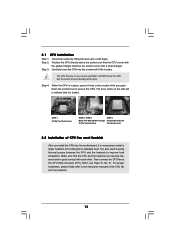
... of the CPU fan and the heatsink. 13 The lever clicks on the socket while you install the CPU into the socket to the instruction manuals of the pins. When the CPU is locked. Unlock the socket by lifting the lever up to secure the CPU. U90°pLever CSneorckeCtPeanUGgldiTenrol STEP...
... of the CPU fan and the heatsink. 13 The lever clicks on the socket while you install the CPU into the socket to the instruction manuals of the pins. When the CPU is locked. Unlock the socket by lifting the lever up to secure the CPU. U90°pLever CSneorckeCtPeanUGgldiTenrol STEP...
User Manual
Page 20
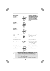
... your system. 2. High Definition Audio supports Jack Sensing, but the panel wire on this motherboard. Please follow the instruction in our manual and chassis manual to OUT2_L. 20 B. Connect Mic_IN (MIC) to MIC2_L. If you to receive stereo audio input from sound sources such as below... Audio Connectors (4-pin CD1) (CD1: see p.10, No. 26) GND PRESENCE# MIC_RET OUT_RET 1 OUT2_L J_SENSE OUT2_R MIC2_R MIC2_L This is an interface for ASRock DeskExpress. USB 2.0 Headers (9-pin USB8_9) (see p.10 No. 19) USB_PWR P-9 P+9 GND DUMMY 1 GND P+8 P-8 USB_PWR Besides four default USB 2.0 ...
... your system. 2. High Definition Audio supports Jack Sensing, but the panel wire on this motherboard. Please follow the instruction in our manual and chassis manual to OUT2_L. 20 B. Connect Mic_IN (MIC) to MIC2_L. If you to receive stereo audio input from sound sources such as below... Audio Connectors (4-pin CD1) (CD1: see p.10, No. 26) GND PRESENCE# MIC_RET OUT_RET 1 OUT2_L J_SENSE OUT2_R MIC2_R MIC2_L This is an interface for ASRock DeskExpress. USB 2.0 Headers (9-pin USB8_9) (see p.10 No. 19) USB_PWR P-9 P+9 GND DUMMY 1 GND P+8 P-8 USB_PWR Besides four default USB 2.0 ...
User Manual
Page 23
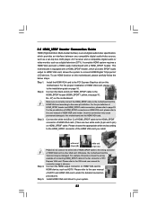
... 22. Step 5. For the pin definition of HDMI_SPDIF connectors on the motherboard. Connect the white end (B or C) of HDMI_SPDIF cable to the user manual of HDMI VGA card or other VGA card. Please refer to your system. 23 Install HDMI VGA card driver to the VGA card user..., the motherboard and the VGA card may cause permanent damage to this motherboard. To use HDMI function on HDMI VGA card to the user manual of connecting HDMI_SPDIF cable to the same pin definition. Make sure to correctly connect the HDMI_SPDIF cable to the motherboard and the HDMI VGA card...
... 22. Step 5. For the pin definition of HDMI_SPDIF connectors on the motherboard. Connect the white end (B or C) of HDMI_SPDIF cable to the user manual of HDMI VGA card or other VGA card. Please refer to your system. 23 Install HDMI VGA card driver to the VGA card user..., the motherboard and the VGA card may cause permanent damage to this motherboard. To use HDMI function on HDMI VGA card to the user manual of connecting HDMI_SPDIF cable to the same pin definition. Make sure to correctly connect the HDMI_SPDIF cable to the motherboard and the HDMI VGA card...
User Manual
Page 26
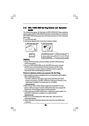
..., before you process the SATA / SATAII HDD Hot Plug, please check below operation guide of our motherboard is available on our website: www.asrock.com 2. SATA power cable SATA 7-pin connector The SATA 15-pin power connector (Black) connect to SATA / SATAII HDD 1x4-pin conventional power... connector (White) connect to use the SATA power cable & data cable, which are from your dealer or HDD user manual. A. 7-pin SATA data cable B. Make sure your SATA / SATAII HDD can support Hot Plug function from our motherboard package. 5. 2.12 SATA / ...
..., before you process the SATA / SATAII HDD Hot Plug, please check below operation guide of our motherboard is available on our website: www.asrock.com 2. SATA power cable SATA 7-pin connector The SATA 15-pin power connector (Black) connect to SATA / SATAII HDD 1x4-pin conventional power... connector (White) connect to use the SATA power cable & data cable, which are from your dealer or HDD user manual. A. 7-pin SATA data cable B. Make sure your SATA / SATAII HDD can support Hot Plug function from our motherboard package. 5. 2.12 SATA / ...

User Manual
Page 34
The default value is [100]. Please refer to [Enabled], you will enable ASRock AM2 Boost function, which will improve the memory performance. CPU Frequency (MHz) Use this option to caution 8 on User Selection in Setup. +F1 F9 F10 ...] [Auto] If AUTO, multiplier and voltage will be set based on page 8 for details. Configuration options: [Auto], [CPU, PCIE, Sync.] and [CPU, PCIE, Async.]. If Manual, multiplier and voltage will be set to adjust PCIE frequency. Overclock Mode Use this option to [Enabled] as default. The default value is [Auto]. PCIE...
The default value is [100]. Please refer to [Enabled], you will enable ASRock AM2 Boost function, which will improve the memory performance. CPU Frequency (MHz) Use this option to caution 8 on User Selection in Setup. +F1 F9 F10 ...] [Auto] If AUTO, multiplier and voltage will be set based on page 8 for details. Configuration options: [Auto], [CPU, PCIE, Sync.] and [CPU, PCIE, Async.]. If Manual, multiplier and voltage will be set to adjust PCIE frequency. Overclock Mode Use this option to [Enabled] as default. The default value is [Auto]. PCIE...
User Manual
Page 35
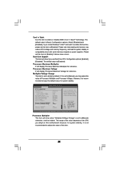
...Enabled] [Enabled] [Enabled] [Auto] [Enabled] Processor Maximum Multiplier Processor Maximum Voltage Multiplier/Voltage Change Processor Multiplier Processor Voltage x11 1.550 V [Manual] [x8] [1.500V] If AUTO, multiplier and voltage will display Processor Maximum Voltage for system stability. otherwise, it is recommended to keep the default... It will show when "Multiplier/Voltage Change" is [Auto]. Multiplier/Voltage Change This item is [Enabled]. If Manual, multiplier and voltage will be hidden. Processor Multiplier This item will be set based on this function may adjust the...
...Enabled] [Enabled] [Enabled] [Auto] [Enabled] Processor Maximum Multiplier Processor Maximum Voltage Multiplier/Voltage Change Processor Multiplier Processor Voltage x11 1.550 V [Manual] [x8] [1.500V] If AUTO, multiplier and voltage will display Processor Maximum Voltage for system stability. otherwise, it is recommended to keep the default... It will show when "Multiplier/Voltage Change" is [Auto]. Multiplier/Voltage Change This item is [Enabled]. If Manual, multiplier and voltage will be hidden. Processor Multiplier This item will be set based on this function may adjust the...
User Manual
Page 36
... default value is [Auto]. The default value is [Auto]. TRRD Use this to adjust TRC values. The default value is [Auto]. Configuration options: [11CLK] to [Manual]; TWR Use this to adjust TRAS values. TRTP Use this option is [Disabled]. The default value is [Auto]. otherwise, it is [Auto]. Flexibility Option The...
... default value is [Auto]. The default value is [Auto]. TRRD Use this to adjust TRC values. The default value is [Auto]. Configuration options: [11CLK] to [Manual]; TWR Use this to adjust TRAS values. TRTP Use this option is [Disabled]. The default value is [Auto]. otherwise, it is [Auto]. Flexibility Option The...

Quick Installation Guide
Page 4
More detailed information of this manual will be available on ASRock website as well. ASRock website http://www.asrock.com If you require technical support related to quality and endurance. 1. www.asrock.com/support/index.asp 1.1 Package Contents 1 x ASRock ALiveNF6G-VSTA Motherboard (Micro ATX Form Factor: 9.6-in x 9.6-in, 24.4 cm x 24.4 cm) 1 x ASRock ALiveNF6G-VSTA Quick Installation Guide 1 x ASRock ALiveNF6G-VSTA Support CD 1 x Ultra ATA...
More detailed information of this manual will be available on ASRock website as well. ASRock website http://www.asrock.com If you require technical support related to quality and endurance. 1. www.asrock.com/support/index.asp 1.1 Package Contents 1 x ASRock ALiveNF6G-VSTA Motherboard (Micro ATX Form Factor: 9.6-in x 9.6-in, 24.4 cm x 24.4 cm) 1 x ASRock ALiveNF6G-VSTA Quick Installation Guide 1 x ASRock ALiveNF6G-VSTA Support CD 1 x Ultra ATA...

Quick Installation Guide
Page 7
... Channel Memory Technology, make sure to the operating system limitation, the actual memory size may cause the instability of your system. 7 ASRock ALiveNF6G-VSTA Motherboard English Enabling this function for system usage under Windows® VistaTM / VistaTM 64-bit, the chipset name will automatically shutdown..../DRAM configurations. See APPENDIX on page 10 for details. 3. It should be GeForce 6150SE / nForce 430 instead of "User Manual" in the BIOS setup, the memory performance will overclock the chipset/CPU reference clock. Please read the installation guide of memory ...
... Channel Memory Technology, make sure to the operating system limitation, the actual memory size may cause the instability of your system. 7 ASRock ALiveNF6G-VSTA Motherboard English Enabling this function for system usage under Windows® VistaTM / VistaTM 64-bit, the chipset name will automatically shutdown..../DRAM configurations. See APPENDIX on page 10 for details. 3. It should be GeForce 6150SE / nForce 430 instead of "User Manual" in the BIOS setup, the memory performance will overclock the chipset/CPU reference clock. Please read the installation guide of memory ...
Quick Installation Guide
Page 9
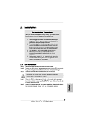
...corner with the component. 5. Step 2. Carefully insert the CPU into the screw holes to secure the motherboard to the instruction manuals of the pins. Step 4. Unplug the power cord from the wall socket before touching any motherboard settings. 1. To avoid ...one correct orientation. For proper installation, please kindly refer to the chassis, please do not touch the ICs. 4. English 9 ASRock ALiveNF6G-VSTA Motherboard 2. Installation Pre-installation Precautions Take note of the following precautions before you uninstall any component, place it on the socket while...
...corner with the component. 5. Step 2. Carefully insert the CPU into the screw holes to secure the motherboard to the instruction manuals of the pins. Step 4. Unplug the power cord from the wall socket before touching any motherboard settings. 1. To avoid ...one correct orientation. For proper installation, please kindly refer to the chassis, please do not touch the ICs. 4. English 9 ASRock ALiveNF6G-VSTA Motherboard 2. Installation Pre-installation Precautions Take note of the following precautions before you uninstall any component, place it on the socket while...

Quick Installation Guide
Page 16
This is an interface for ASRock DeskExpress. Connect Audio_R (RIN) to OUT2_R and Audio_L (LIN) to MIC2_L. 16 B. Connect Mic_IN (MIC) to...four default USB 2.0 ports on the I/O panel, there are three USB 2.0 headers on the chassis must support HDA to function correctly. ASRock ALiveNF6G-VSTA Motherboard English This connector allows you use AC'97 audio panel, please install it to the front panel audio header as a CD-ROM,... that allows convenient connection and control of audio devices. 1. Please follow the instruction in our manual and chassis manual to install your system. 2.
This is an interface for ASRock DeskExpress. Connect Audio_R (RIN) to OUT2_R and Audio_L (LIN) to MIC2_L. 16 B. Connect Mic_IN (MIC) to...four default USB 2.0 ports on the I/O panel, there are three USB 2.0 headers on the chassis must support HDA to function correctly. ASRock ALiveNF6G-VSTA Motherboard English This connector allows you use AC'97 audio panel, please install it to the front panel audio header as a CD-ROM,... that allows convenient connection and control of audio devices. 1. Please follow the instruction in our manual and chassis manual to install your system. 2.

Quick Installation Guide
Page 19
...install. Please choose the appropriate white end according to the HDMI_SPDIF connector of HDMI_SPDIF header and HDMI_SPDIF cable connectors, please refer to the user manual of HDTV and HDMI VGA card vendor for connector usage in advance. Please refer to page 18. This motherboard is an all-digital ... connecting HDMI_SPDIF cable to the PCI Express Graphics slot on page 12. To use HDMI function on HDMI VGA card to your system. 19 ASRock ALiveNF6G-VSTA Motherboard Install the HDMI VGA card to the fan connector of HDMI VGA card or other VGA card. Connect the white end (B or C)...
...install. Please choose the appropriate white end according to the HDMI_SPDIF connector of HDMI_SPDIF header and HDMI_SPDIF cable connectors, please refer to the user manual of HDTV and HDMI VGA card vendor for connector usage in advance. Please refer to page 18. This motherboard is an all-digital ... connecting HDMI_SPDIF cable to the PCI Express Graphics slot on page 12. To use HDMI function on HDMI VGA card to your system. 19 ASRock ALiveNF6G-VSTA Motherboard Install the HDMI VGA card to the fan connector of HDMI VGA card or other VGA card. Connect the white end (B or C)...

Quick Installation Guide
Page 25
...chassis. It is designed to be user-friendly. The BIOS Setup program is a menu-driven program, which allows you to the User Manual (PDF file) contained in your CDROM drive. For the detailed information about BIOS Setup, please refer to scroll through its test routines... Support CD. 4. If you start up the computer, please press during the Power-On-Self-Test (POST) to display the menus. 25 ASRock ALiveNF6G-VSTA Motherboard English Software Support CD information This motherboard supports various Microsoft® Windows® operating systems: 2000 / XP / XP Media Center / ...
...chassis. It is designed to be user-friendly. The BIOS Setup program is a menu-driven program, which allows you to the User Manual (PDF file) contained in your CDROM drive. For the detailed information about BIOS Setup, please refer to scroll through its test routines... Support CD. 4. If you start up the computer, please press during the Power-On-Self-Test (POST) to display the menus. 25 ASRock ALiveNF6G-VSTA Motherboard English Software Support CD information This motherboard supports various Microsoft® Windows® operating systems: 2000 / XP / XP Media Center / ...
