User Manual
Page 4
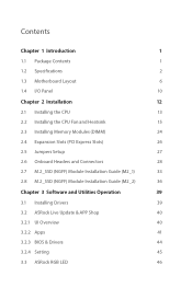
... the CPU 13 2.2 Installing the CPU Fan and Heatsink 15 2.3 Installing Memory Modules (DIMM) 24 2.4 Expansion Slots (PCI Express Slots) 26 2.5 Jumpers Setup 27 2.6 Onboard Headers and Connectors 28 2.7 M.2_SSD (NGFF) Module Installation Guide (M2_1) 33 2.8 M.2_SSD (NGFF) Module Installation Guide (M2_2) 36 Chapter 3 Software and Utilities Operation 39 3.1 Installing Drivers...
... the CPU 13 2.2 Installing the CPU Fan and Heatsink 15 2.3 Installing Memory Modules (DIMM) 24 2.4 Expansion Slots (PCI Express Slots) 26 2.5 Jumpers Setup 27 2.6 Onboard Headers and Connectors 28 2.7 M.2_SSD (NGFF) Module Installation Guide (M2_1) 33 2.8 M.2_SSD (NGFF) Module Installation Guide (M2_2) 36 Chapter 3 Software and Utilities Operation 39 3.1 Installing Drivers...
User Manual
Page 9
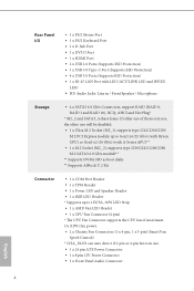
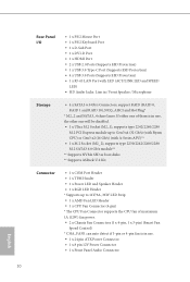
.../2260/2280 M.2 SATA3 6.0 Gb/s module** ** Supports NVMe SSD as boot disks ** Supports ASRock U.2 Kit Connector • 1 x COM Port Header • 1 x TPM Header • 1 x Power LED and Speaker Header • 1 x RGB LED Header * Supports up to 12V/3A, 36W LED Strip • 1 x AMD Fan LED Header • 1 x CPU Fan Connector (4-pin) * The CPU Fan Connector supports the CPU...
.../2260/2280 M.2 SATA3 6.0 Gb/s module** ** Supports NVMe SSD as boot disks ** Supports ASRock U.2 Kit Connector • 1 x COM Port Header • 1 x TPM Header • 1 x Power LED and Speaker Header • 1 x RGB LED Header * Supports up to 12V/3A, 36W LED Strip • 1 x AMD Fan LED Header • 1 x CPU Fan Connector (4-pin) * The CPU Fan Connector supports the CPU...

User Manual
Page 12
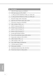
...4 2 x 288-pin DDR4 DIMM Slots (DDR4_A2, DDR4_B2) 5 RGB LED Header (RGB_HEADER1) 6 AMD Fan LED Header (AMD_FAN_LED1) 7 ATX Power Connector (ATXPWR1) 8 USB 3.0 Header (USB3_3_4) 9 AMD LED Fan USB Header (USB_5) 10 SATA3 Connector (SATA3_3) 11 SATA3 Connector (SATA3_4) 12...Header (PANEL1) 15 Power LED and Speaker Header (SPK_PLED1) 16 Chassis Fan Connector (CHA_FAN2) 17 USB 2.0 Header (USB_2_3) 18 USB 2.0 Header (USB_2_4) 19 Clear CMOS Jumper (CLRCMOS1) 20 COM Port Header (COM1) 21 TPM Header (TPMS1) 22 Front Panel Audio Header (HD_AUDIO1) 23 Chassis Fan Connector (CHA_FAN1) AB350M Pro4 A320M Pro4...
...4 2 x 288-pin DDR4 DIMM Slots (DDR4_A2, DDR4_B2) 5 RGB LED Header (RGB_HEADER1) 6 AMD Fan LED Header (AMD_FAN_LED1) 7 ATX Power Connector (ATXPWR1) 8 USB 3.0 Header (USB3_3_4) 9 AMD LED Fan USB Header (USB_5) 10 SATA3 Connector (SATA3_3) 11 SATA3 Connector (SATA3_4) 12...Header (PANEL1) 15 Power LED and Speaker Header (SPK_PLED1) 16 Chassis Fan Connector (CHA_FAN2) 17 USB 2.0 Header (USB_2_3) 18 USB 2.0 Header (USB_2_4) 19 Clear CMOS Jumper (CLRCMOS1) 20 COM Port Header (COM1) 21 TPM Header (TPMS1) 22 Front Panel Audio Header (HD_AUDIO1) 23 Chassis Fan Connector (CHA_FAN1) AB350M Pro4 A320M Pro4...

User Manual
Page 14
...DDR4_A1, DDR4_B1) 4 2 x 288-pin DDR4 DIMM Slots (DDR4_A2, DDR4_B2) 5 RGB LED Header (RGB_HEADER1) 6 AMD Fan LED Header (AMD_FAN_LED1) 7 ATX Power Connector (ATXPWR1) 8 USB 3.0 Header (USB3_3_4) 9 SATA3 Connector (SATA3_3) 10 SATA3 Connector (SATA3_4) 11 SATA3 Connector...Header (PANEL1) 14 Power LED and Speaker Header (SPK_PLED1) 15 Chassis Fan Connector (CHA_FAN2) 16 USB 2.0 Header (USB_2_3) 17 USB 2.0 Header (USB_2_4) 18 Clear CMOS Jumper (CLRCMOS1) 19 COM Port Header (COM1) 20 TPM Header (TPMS1) 21 Front Panel Audio Header (HD_AUDIO1) 22 Chassis Fan Connector (CHA_FAN1) AB350M Pro4 A320M Pro4...
...DDR4_A1, DDR4_B1) 4 2 x 288-pin DDR4 DIMM Slots (DDR4_A2, DDR4_B2) 5 RGB LED Header (RGB_HEADER1) 6 AMD Fan LED Header (AMD_FAN_LED1) 7 ATX Power Connector (ATXPWR1) 8 USB 3.0 Header (USB3_3_4) 9 SATA3 Connector (SATA3_3) 10 SATA3 Connector (SATA3_4) 11 SATA3 Connector...Header (PANEL1) 14 Power LED and Speaker Header (SPK_PLED1) 15 Chassis Fan Connector (CHA_FAN2) 16 USB 2.0 Header (USB_2_3) 17 USB 2.0 Header (USB_2_4) 18 Clear CMOS Jumper (CLRCMOS1) 19 COM Port Header (COM1) 20 TPM Header (TPMS1) 21 Front Panel Audio Header (HD_AUDIO1) 22 Chassis Fan Connector (CHA_FAN1) AB350M Pro4 A320M Pro4...
User Manual
Page 24
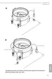
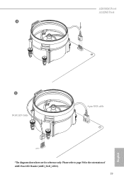
AB350M Pro4 A320M Pro4 4 CPU_FAN1 5 RGB LED Cable 4-pin FAN cable CPU_FAN1 +12V AMD_FAN_LED1 *The diagram shown here are for the orientation of AMD Fan LED Header (AMD_FAN_LED1). 19 English Please refer to page 32 for reference only.
AB350M Pro4 A320M Pro4 4 CPU_FAN1 5 RGB LED Cable 4-pin FAN cable CPU_FAN1 +12V AMD_FAN_LED1 *The diagram shown here are for the orientation of AMD Fan LED Header (AMD_FAN_LED1). 19 English Please refer to page 32 for reference only.
User Manual
Page 28
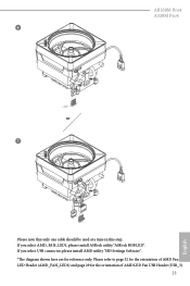
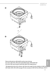
Please refer to page 32 for the orientation of AMD Fan LED Header (AMD_FAN_LED1) and page 29 for reference only. AB350M Pro4 A320M Pro4 6 CPU_FAN1 +12V AMD_FAN_LED1 or 7 CPU_FAN1 AMD_FAN_LED1 USB_5 Please note that only one cable should be used at a time in this step. If you select AMD_FAN_LED1, please install ASRock utility "ASRock RGB LED". If you select USB connector, please install AMD utility "SR3 Settings Software". *The diagram shown here are for the orientation of AMD LED Fan USB Header (USB_5). 23 English
Please refer to page 32 for the orientation of AMD Fan LED Header (AMD_FAN_LED1) and page 29 for reference only. AB350M Pro4 A320M Pro4 6 CPU_FAN1 +12V AMD_FAN_LED1 or 7 CPU_FAN1 AMD_FAN_LED1 USB_5 Please note that only one cable should be used at a time in this step. If you select AMD_FAN_LED1, please install ASRock utility "ASRock RGB LED". If you select USB connector, please install AMD utility "SR3 Settings Software". *The diagram shown here are for the orientation of AMD LED Fan USB Header (USB_5). 23 English
User Manual
Page 37
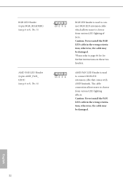
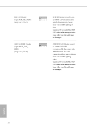
... 32 The cable connection allows users to choose from various LED lighting effects. RGB LED Header (4-pin RGB_HEADER1) (see p.6 or 8, No. 5) AMD FAN LED Header (4-pin AMD_FAN_ LED1) (see p.6 or 8, No. 6) 1 12V G R B 1 12V G R B RGB LED header is used to connect RGB LED extension cable which allows users to choose from various LED lighting effects. Caution: Never...
... 32 The cable connection allows users to choose from various LED lighting effects. RGB LED Header (4-pin RGB_HEADER1) (see p.6 or 8, No. 5) AMD FAN LED Header (4-pin AMD_FAN_ LED1) (see p.6 or 8, No. 6) 1 12V G R B 1 12V G R B RGB LED header is used to connect RGB LED extension cable which allows users to choose from various LED lighting effects. Caution: Never...
User Manual
Page 51
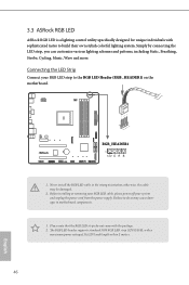
... the LED Strip Connect your system and unplug the power cord from the power supply. 3.3 ASRock RGB LED ASRock RGB LED is a lighting control utility specifically designed for unique individuals with the package. 2. otherwise,... the cable may cause damages to build their own stylish colorful lighting system. Failure to do not come with sophisticated tastes to motherboard components. 1. Never install the RGB LED cable in the wrong orientation; The RGB LED header...
... the LED Strip Connect your system and unplug the power cord from the power supply. 3.3 ASRock RGB LED ASRock RGB LED is a lighting control utility specifically designed for unique individuals with the package. 2. otherwise,... the cable may cause damages to build their own stylish colorful lighting system. Failure to do not come with sophisticated tastes to motherboard components. 1. Never install the RGB LED cable in the wrong orientation; The RGB LED header...

Quick Installation Guide
Page 4
... Fan Connector (CPU_FAN1) 3 2 x 288-pin DDR4 DIMM Slots (DDR4_A1, DDR4_B1) 4 2 x 288-pin DDR4 DIMM Slots (DDR4_A2, DDR4_B2) 5 RGB LED Header (RGB_HEADER1) 6 AMD Fan LED Header (AMD_FAN_LED1) 7 ATX Power Connector (ATXPWR1) 8 USB 3.0 Header (USB3_3_4) 9 AMD LED Fan USB Header (USB_5) 10 SATA3 Connector (SATA3_3) 11 SATA3 Connector (SATA3_4) 12 SATA3 Connector (SATA3_2) 13 SATA3 Connector (SATA3_1...
... Fan Connector (CPU_FAN1) 3 2 x 288-pin DDR4 DIMM Slots (DDR4_A1, DDR4_B1) 4 2 x 288-pin DDR4 DIMM Slots (DDR4_A2, DDR4_B2) 5 RGB LED Header (RGB_HEADER1) 6 AMD Fan LED Header (AMD_FAN_LED1) 7 ATX Power Connector (ATXPWR1) 8 USB 3.0 Header (USB3_3_4) 9 AMD LED Fan USB Header (USB_5) 10 SATA3 Connector (SATA3_3) 11 SATA3 Connector (SATA3_4) 12 SATA3 Connector (SATA3_2) 13 SATA3 Connector (SATA3_1...
Quick Installation Guide
Page 6
... Connector (ATX12V1) 2 CPU Fan Connector (CPU_FAN1) 3 2 x 288-pin DDR4 DIMM Slots (DDR4_A1, DDR4_B1) 4 2 x 288-pin DDR4 DIMM Slots (DDR4_A2, DDR4_B2) 5 RGB LED Header (RGB_HEADER1) 6 AMD Fan LED Header (AMD_FAN_LED1) 7 ATX Power Connector (ATXPWR1) 8 USB 3.0 Header (USB3_3_4) 9 SATA3 Connector (SATA3_3) 10 SATA3 Connector (SATA3_4) 11 SATA3 Connector (SATA3_2) 12 SATA3 Connector (SATA3_1) 13 System Panel...
... Connector (ATX12V1) 2 CPU Fan Connector (CPU_FAN1) 3 2 x 288-pin DDR4 DIMM Slots (DDR4_A1, DDR4_B1) 4 2 x 288-pin DDR4 DIMM Slots (DDR4_A2, DDR4_B2) 5 RGB LED Header (RGB_HEADER1) 6 AMD Fan LED Header (AMD_FAN_LED1) 7 ATX Power Connector (ATXPWR1) 8 USB 3.0 Header (USB3_3_4) 9 SATA3 Connector (SATA3_3) 10 SATA3 Connector (SATA3_4) 11 SATA3 Connector (SATA3_2) 12 SATA3 Connector (SATA3_1) 13 System Panel...
Quick Installation Guide
Page 12
.../2260/2280 M.2 SATA3 6.0 Gb/s module** ** Supports NVMe SSD as boot disks ** Supports ASRock U.2 Kit Connector • 1 x COM Port Header • 1 x TPM Header • 1 x Power LED and Speaker Header • 1 x RGB LED Header * Supports up to 12V/3A, 36W LED Strip • 1 x AMD Fan LED Header • 1 x CPU Fan Connector (4-pin) * The CPU Fan Connector supports the CPU...
.../2260/2280 M.2 SATA3 6.0 Gb/s module** ** Supports NVMe SSD as boot disks ** Supports ASRock U.2 Kit Connector • 1 x COM Port Header • 1 x TPM Header • 1 x Power LED and Speaker Header • 1 x RGB LED Header * Supports up to 12V/3A, 36W LED Strip • 1 x AMD Fan LED Header • 1 x CPU Fan Connector (4-pin) * The CPU Fan Connector supports the CPU...
Quick Installation Guide
Page 21
AB350M Pro4 A320M Pro4 4 CPU_FAN1 5 RGB LED Cable 4-pin FAN cable CPU_FAN1 +12V AMD_FAN_LED1 *The diagram shown here are for the orientation of AMD Fan LED Header (AMD_FAN_LED1). 19 English Please refer to page 30 for reference only.
AB350M Pro4 A320M Pro4 4 CPU_FAN1 5 RGB LED Cable 4-pin FAN cable CPU_FAN1 +12V AMD_FAN_LED1 *The diagram shown here are for the orientation of AMD Fan LED Header (AMD_FAN_LED1). 19 English Please refer to page 30 for reference only.
Quick Installation Guide
Page 25
If you select AMD_FAN_LED1, please install ASRock utility "ASRock RGB LED". Please refer to page 32 for the orientation of AMD Fan LED Header (AMD_FAN_LED1) and page 29 for reference only. If you select USB connector, please install AMD utility "SR3 Settings Software". *The diagram shown here are for the orientation of AMD LED Fan USB Header (USB_5). 23 English AB350M Pro4 A320M Pro4 6 CPU_FAN1 +12V AMD_FAN_LED1 or 7 CPU_FAN1 AMD_FAN_LED1 USB_5 Please note that only one cable should be used at a time in this step.
If you select AMD_FAN_LED1, please install ASRock utility "ASRock RGB LED". Please refer to page 32 for the orientation of AMD Fan LED Header (AMD_FAN_LED1) and page 29 for reference only. If you select USB connector, please install AMD utility "SR3 Settings Software". *The diagram shown here are for the orientation of AMD LED Fan USB Header (USB_5). 23 English AB350M Pro4 A320M Pro4 6 CPU_FAN1 +12V AMD_FAN_LED1 or 7 CPU_FAN1 AMD_FAN_LED1 USB_5 Please note that only one cable should be used at a time in this step.
Quick Installation Guide
Page 34
... AMD heatsink. The cable connection allows users to choose from various LED lighting effects. RGB LED Header (4-pin RGB_HEADER1) (see p.1 or 3, No. 5) AMD FAN LED Header (4-pin AMD_FAN_ LED1) (see p.1 or 3, No. 6) 1 12V G R B 1 12V G R B RGB LED header is used to connect RGB LED extension cable which allows users to choose from various LED lighting effects. Caution...
... AMD heatsink. The cable connection allows users to choose from various LED lighting effects. RGB LED Header (4-pin RGB_HEADER1) (see p.1 or 3, No. 5) AMD FAN LED Header (4-pin AMD_FAN_ LED1) (see p.1 or 3, No. 6) 1 12V G R B 1 12V G R B RGB LED header is used to connect RGB LED extension cable which allows users to choose from various LED lighting effects. Caution...


