User Manual
Page 4
... Chapter 2 Installation 12 2.1 Installing the CPU 13 2.2 Installing the CPU Fan and Heatsink 15 2.3 Installing Memory Modules (DIMM) 24 2.4 Expansion Slots (PCI Express Slots) 26 2.5 Jumpers Setup 27 2.6 Onboard Headers and Connectors 28 2.7 M.2_SSD (NGFF) Module Installation Guide (M2_1) 33... 2.8 M.2_SSD (NGFF) Module Installation Guide (M2_2) 36 Chapter 3 Software and Utilities Operation 39 3.1 Installing Drivers 39 3.2 ASRock Live Update & APP Shop 40...
... Chapter 2 Installation 12 2.1 Installing the CPU 13 2.2 Installing the CPU Fan and Heatsink 15 2.3 Installing Memory Modules (DIMM) 24 2.4 Expansion Slots (PCI Express Slots) 26 2.5 Jumpers Setup 27 2.6 Onboard Headers and Connectors 28 2.7 M.2_SSD (NGFF) Module Installation Guide (M2_1) 33... 2.8 M.2_SSD (NGFF) Module Installation Guide (M2_2) 36 Chapter 3 Software and Utilities Operation 39 3.1 Installing Drivers 39 3.2 ASRock Live Update & APP Shop 40...
User Manual
Page 9
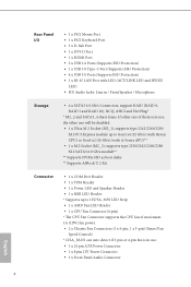
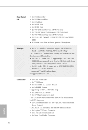
...2280 M.2 SATA3 6.0 Gb/s module** ** Supports NVMe SSD as boot disks ** Supports ASRock U.2 Kit Connector • 1 x COM Port Header • 1 x TPM Header • 1 x Power LED and Speaker Header • 1 x RGB LED Header * Supports up to Gen3 x4 (32 Gb/s) (with Ryzen CPU) or Gen3 x2... Strip • 1 x AMD Fan LED Header • 1 x CPU Fan Connector (4-pin) * The CPU Fan Connector supports the CPU fan of maximum 1A (12W) fan power. • 2 x Chassis Fan Connectors (1 x 4-pin, 1 x 3-pin) (Smart Fan Speed Control) * CHA_FAN1 can auto detect if 3-pin or 4-pin fan is in / Front Speaker / ...
...2280 M.2 SATA3 6.0 Gb/s module** ** Supports NVMe SSD as boot disks ** Supports ASRock U.2 Kit Connector • 1 x COM Port Header • 1 x TPM Header • 1 x Power LED and Speaker Header • 1 x RGB LED Header * Supports up to Gen3 x4 (32 Gb/s) (with Ryzen CPU) or Gen3 x2... Strip • 1 x AMD Fan LED Header • 1 x CPU Fan Connector (4-pin) * The CPU Fan Connector supports the CPU fan of maximum 1A (12W) fan power. • 2 x Chassis Fan Connectors (1 x 4-pin, 1 x 3-pin) (Smart Fan Speed Control) * CHA_FAN1 can auto detect if 3-pin or 4-pin fan is in / Front Speaker / ...

User Manual
Page 10
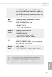
...® 10 64-bit * For the updated Windows® 10 driver, please visit ASRock's web- It should be done at your system. AB350M Pro4 A320M Pro4 • 1 x AMD LED Fan USB Header (for AB350M Pro4 only) • 2 x USB 2.0 Headers (Support 4 USB 2.0 ports) (Supports ESD Protection) • 1 x USB 3.0 Header (Supports 2 USB 3.0 ports) (Supports ESD Protection) BIOS Feature • AMI UEFI Legal...
...® 10 64-bit * For the updated Windows® 10 driver, please visit ASRock's web- It should be done at your system. AB350M Pro4 A320M Pro4 • 1 x AMD LED Fan USB Header (for AB350M Pro4 only) • 2 x USB 2.0 Headers (Support 4 USB 2.0 ports) (Supports ESD Protection) • 1 x USB 3.0 Header (Supports 2 USB 3.0 ports) (Supports ESD Protection) BIOS Feature • AMI UEFI Legal...

User Manual
Page 12
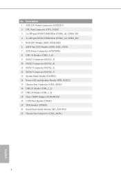
...2 x 288-pin DDR4 DIMM Slots (DDR4_A2, DDR4_B2) 5 RGB LED Header (RGB_HEADER1) 6 AMD Fan LED Header (AMD_FAN_LED1) 7 ATX Power Connector (ATXPWR1) 8 USB 3.0 Header (USB3_3_4) 9 AMD LED Fan USB Header (USB_5) 10 SATA3 Connector (SATA3_3) 11 SATA3 Connector (SATA3_4) 12 ...Header (PANEL1) 15 Power LED and Speaker Header (SPK_PLED1) 16 Chassis Fan Connector (CHA_FAN2) 17 USB 2.0 Header (USB_2_3) 18 USB 2.0 Header (USB_2_4) 19 Clear CMOS Jumper (CLRCMOS1) 20 COM Port Header (COM1) 21 TPM Header (TPMS1) 22 Front Panel Audio Header (HD_AUDIO1) 23 Chassis Fan Connector (CHA_FAN1) AB350M Pro4 A320M Pro4...
...2 x 288-pin DDR4 DIMM Slots (DDR4_A2, DDR4_B2) 5 RGB LED Header (RGB_HEADER1) 6 AMD Fan LED Header (AMD_FAN_LED1) 7 ATX Power Connector (ATXPWR1) 8 USB 3.0 Header (USB3_3_4) 9 AMD LED Fan USB Header (USB_5) 10 SATA3 Connector (SATA3_3) 11 SATA3 Connector (SATA3_4) 12 ...Header (PANEL1) 15 Power LED and Speaker Header (SPK_PLED1) 16 Chassis Fan Connector (CHA_FAN2) 17 USB 2.0 Header (USB_2_3) 18 USB 2.0 Header (USB_2_4) 19 Clear CMOS Jumper (CLRCMOS1) 20 COM Port Header (COM1) 21 TPM Header (TPMS1) 22 Front Panel Audio Header (HD_AUDIO1) 23 Chassis Fan Connector (CHA_FAN1) AB350M Pro4 A320M Pro4...

User Manual
Page 14
... Connector (SATA3_2) 12 SATA3 Connector (SATA3_1) 13 System Panel Header (PANEL1) 14 Power LED and Speaker Header (SPK_PLED1) 15 Chassis Fan Connector (CHA_FAN2) 16 USB 2.0 Header (USB_2_3) 17 USB 2.0 Header (USB_2_4) 18 Clear CMOS Jumper (CLRCMOS1) 19 COM Port Header (COM1) 20 TPM Header (TPMS1) 21 Front Panel Audio Header (HD_AUDIO1) 22 Chassis Fan Connector (CHA_FAN1) AB350M Pro4 A320M Pro4 English 9 No.
... Connector (SATA3_2) 12 SATA3 Connector (SATA3_1) 13 System Panel Header (PANEL1) 14 Power LED and Speaker Header (SPK_PLED1) 15 Chassis Fan Connector (CHA_FAN2) 16 USB 2.0 Header (USB_2_3) 17 USB 2.0 Header (USB_2_4) 18 Clear CMOS Jumper (CLRCMOS1) 19 COM Port Header (COM1) 20 TPM Header (TPMS1) 21 Front Panel Audio Header (HD_AUDIO1) 22 Chassis Fan Connector (CHA_FAN1) AB350M Pro4 A320M Pro4 English 9 No.
User Manual
Page 24
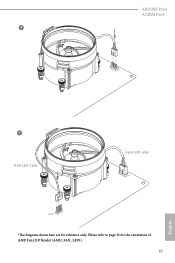
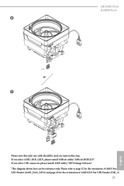
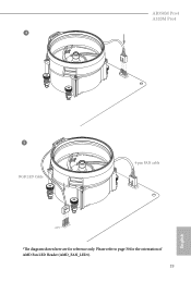
AB350M Pro4 A320M Pro4 4 CPU_FAN1 5 RGB LED Cable 4-pin FAN cable CPU_FAN1 +12V AMD_FAN_LED1 *The diagram shown here are for the orientation of AMD Fan LED Header (AMD_FAN_LED1). 19 English Please refer to page 32 for reference only.
AB350M Pro4 A320M Pro4 4 CPU_FAN1 5 RGB LED Cable 4-pin FAN cable CPU_FAN1 +12V AMD_FAN_LED1 *The diagram shown here are for the orientation of AMD Fan LED Header (AMD_FAN_LED1). 19 English Please refer to page 32 for reference only.
User Manual
Page 28
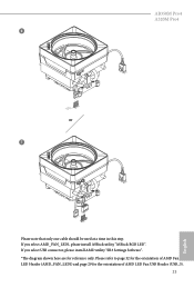
Please refer to page 32 for the orientation of AMD LED Fan USB Header (USB_5). 23 English AB350M Pro4 A320M Pro4 6 CPU_FAN1 +12V AMD_FAN_LED1 or 7 CPU_FAN1 AMD_FAN_LED1 USB_5 Please note that only one cable should be used at a time in this step. If you select USB connector, please install AMD utility "SR3 Settings Software". *The diagram shown here are for the orientation of AMD Fan LED Header (AMD_FAN_LED1) and page 29 for reference only. If you select AMD_FAN_LED1, please install ASRock utility "ASRock RGB LED".
Please refer to page 32 for the orientation of AMD LED Fan USB Header (USB_5). 23 English AB350M Pro4 A320M Pro4 6 CPU_FAN1 +12V AMD_FAN_LED1 or 7 CPU_FAN1 AMD_FAN_LED1 USB_5 Please note that only one cable should be used at a time in this step. If you select USB connector, please install AMD utility "SR3 Settings Software". *The diagram shown here are for the orientation of AMD Fan LED Header (AMD_FAN_LED1) and page 29 for reference only. If you select AMD_FAN_LED1, please install ASRock utility "ASRock RGB LED".

User Manual
Page 34
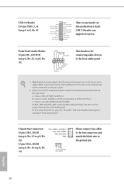
... speaker to 6.0 Gb/s data transfer rate. * M2_2 and SATA3_4 share lanes. Each USB 2.0 header can support two ports. AMD LED Fan USB Header (4-pin USB_5) (see p.6, No. 9) This header is in use, the other one of them is used for internal storage devices with up to ... p.6, No. 11 or p.8, No. 10) SATA3_1 SATA3_3 SATA3_2 SATA3_4 SPEAKER DUMMY DUMMY +5V 1 PLED+ PLED+ PLED- If either one will be disabled. AB350M Pro4 A320M Pro4 Power LED and Speaker Header (7-pin SPK_PLED1) (see p.6, No. 15 or p.8, No. 14) Serial ATA3 Connectors (SATA3_1: see p.6, No. 13 or p.8, No. 12) (SATA3_2...
... speaker to 6.0 Gb/s data transfer rate. * M2_2 and SATA3_4 share lanes. Each USB 2.0 header can support two ports. AMD LED Fan USB Header (4-pin USB_5) (see p.6, No. 9) This header is in use, the other one of them is used for internal storage devices with up to ... p.6, No. 11 or p.8, No. 10) SATA3_1 SATA3_3 SATA3_2 SATA3_4 SPEAKER DUMMY DUMMY +5V 1 PLED+ PLED+ PLED- If either one will be disabled. AB350M Pro4 A320M Pro4 Power LED and Speaker Header (7-pin SPK_PLED1) (see p.6, No. 15 or p.8, No. 14) Serial ATA3 Connectors (SATA3_1: see p.6, No. 13 or p.8, No. 12) (SATA3_2...
User Manual
Page 35
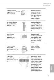
Each USB 3.0 header can support two ports. Connect Audio_R (RIN) to OUT2_R and Audio_L (LIN) to Ground (GND). Connect Ground (GND) to OUT2_L. Chassis Fan Connectors (4-pin CHA_FAN1) (see p.6, No. 23 or p.8, No. 22) (3-pin CHA_FAN2) (see p.6... or 8, No. 8) Vbus IntA_PA_SSRXIntA_PA_SSRX+ GND IntA_PA_SSTXIntA_PA_SSTX+ GND IntA_PA_DIntA_PA_D+ Vbus IntA_PB_SSRXIntA_PB_SSRX+ GND IntA_PB_SSTXIntA_PB_SSTX+ GND IntA_PB_DIntA_PB_D+ Dummy 1 There is for the HD audio panel only. Front Panel Audio Header...
Each USB 3.0 header can support two ports. Connect Audio_R (RIN) to OUT2_R and Audio_L (LIN) to Ground (GND). Connect Ground (GND) to OUT2_L. Chassis Fan Connectors (4-pin CHA_FAN1) (see p.6, No. 23 or p.8, No. 22) (3-pin CHA_FAN2) (see p.6... or 8, No. 8) Vbus IntA_PA_SSRXIntA_PA_SSRX+ GND IntA_PA_SSTXIntA_PA_SSTX+ GND IntA_PA_DIntA_PA_D+ Vbus IntA_PB_SSRXIntA_PB_SSRX+ GND IntA_PB_SSTXIntA_PB_SSTX+ GND IntA_PB_DIntA_PB_D+ Dummy 1 There is for the HD audio panel only. Front Panel Audio Header...

User Manual
Page 36
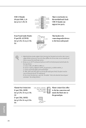
...or p.8, No. 19) RRXD1 DDTR#1 DDSR#1 CCTS#1 1 RRI#1 RRTS#1 GND TTXD1 DDCD#1 This COM1 header supports a serial port module. Serial Port Header (9-pin COM1) (see p.6 or 8, No. 2) (Quiet Fan) connector. If you plan to Pin 1-3. ATX 12V Power Connector (8-pin ATX12V1) (see p.6 or 8,...power connector. A TPM system also helps enhance network security, protects digital identities, and ensures platform integrity. 31 English AB350M Pro4 A320M Pro4 CPU Fan Connector FAN_SPEED This motherboard pro- TPM Header (17-pin TPMS1) (see p.6, No. 21 or p.8, No. 20) GND SERIRQ # S_PWRDWN # GN D ...
...or p.8, No. 19) RRXD1 DDTR#1 DDSR#1 CCTS#1 1 RRI#1 RRTS#1 GND TTXD1 DDCD#1 This COM1 header supports a serial port module. Serial Port Header (9-pin COM1) (see p.6 or 8, No. 2) (Quiet Fan) connector. If you plan to Pin 1-3. ATX 12V Power Connector (8-pin ATX12V1) (see p.6 or 8,...power connector. A TPM system also helps enhance network security, protects digital identities, and ensures platform integrity. 31 English AB350M Pro4 A320M Pro4 CPU Fan Connector FAN_SPEED This motherboard pro- TPM Header (17-pin TPMS1) (see p.6, No. 21 or p.8, No. 20) GND SERIRQ # S_PWRDWN # GN D ...
User Manual
Page 37
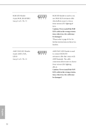
... refer to choose from various LED lighting effects. Caution: Never install the FAN LED cable in the wrong orientation; Caution: Never install the RGB LED cable in the wrong orientation; RGB LED Header (4-pin RGB_HEADER1) (see p.6 or 8, No. 5) AMD FAN LED Header (4-pin AMD_FAN_ LED1) (see p.6 or 8, No. 6) 1 12V... G R B 1 12V G R B RGB LED header is used to connect RGB LED extension cable which allows users...
... refer to choose from various LED lighting effects. Caution: Never install the FAN LED cable in the wrong orientation; Caution: Never install the RGB LED cable in the wrong orientation; RGB LED Header (4-pin RGB_HEADER1) (see p.6 or 8, No. 5) AMD FAN LED Header (4-pin AMD_FAN_ LED1) (see p.6 or 8, No. 6) 1 12V... G R B 1 12V G R B RGB LED header is used to connect RGB LED extension cable which allows users...

Quick Installation Guide
Page 4
... (CPU_FAN1) 3 2 x 288-pin DDR4 DIMM Slots (DDR4_A1, DDR4_B1) 4 2 x 288-pin DDR4 DIMM Slots (DDR4_A2, DDR4_B2) 5 RGB LED Header (RGB_HEADER1) 6 AMD Fan LED Header (AMD_FAN_LED1) 7 ATX Power Connector (ATXPWR1) 8 USB 3.0 Header (USB3_3_4) 9 AMD LED Fan USB Header (USB_5) 10 SATA3 Connector (SATA3_3) 11 SATA3 Connector (SATA3_4) 12 SATA3 Connector (SATA3_2) 13 SATA3 Connector (SATA3_1) 14 System Panel...
... (CPU_FAN1) 3 2 x 288-pin DDR4 DIMM Slots (DDR4_A1, DDR4_B1) 4 2 x 288-pin DDR4 DIMM Slots (DDR4_A2, DDR4_B2) 5 RGB LED Header (RGB_HEADER1) 6 AMD Fan LED Header (AMD_FAN_LED1) 7 ATX Power Connector (ATXPWR1) 8 USB 3.0 Header (USB3_3_4) 9 AMD LED Fan USB Header (USB_5) 10 SATA3 Connector (SATA3_3) 11 SATA3 Connector (SATA3_4) 12 SATA3 Connector (SATA3_2) 13 SATA3 Connector (SATA3_1) 14 System Panel...
Quick Installation Guide
Page 6
... SATA3 Connector (SATA3_2) 12 SATA3 Connector (SATA3_1) 13 System Panel Header (PANEL1) 14 Power LED and Speaker Header (SPK_PLED1) 15 Chassis Fan Connector (CHA_FAN2) 16 USB 2.0 Header (USB_2_3) 17 USB 2.0 Header (USB_2_4) 18 Clear CMOS Jumper (CLRCMOS1) 19 COM Port Header (COM1) 20 TPM Header (TPMS1) 21 Front Panel Audio Header (HD_AUDIO1) 22 Chassis Fan Connector (CHA_FAN1) 4 English No.
... SATA3 Connector (SATA3_2) 12 SATA3 Connector (SATA3_1) 13 System Panel Header (PANEL1) 14 Power LED and Speaker Header (SPK_PLED1) 15 Chassis Fan Connector (CHA_FAN2) 16 USB 2.0 Header (USB_2_3) 17 USB 2.0 Header (USB_2_4) 18 Clear CMOS Jumper (CLRCMOS1) 19 COM Port Header (COM1) 20 TPM Header (TPMS1) 21 Front Panel Audio Header (HD_AUDIO1) 22 Chassis Fan Connector (CHA_FAN1) 4 English No.
Quick Installation Guide
Page 12
... ** Supports ASRock U.2 Kit Connector • 1 x COM Port Header • 1 x TPM Header • 1 x Power LED and Speaker Header • 1 x RGB LED Header * Supports up to 12V/3A, 36W LED Strip • 1 x AMD Fan LED Header • 1 x CPU Fan Connector (4-pin) * The CPU Fan Connector supports the CPU fan of maximum 1A (12W) fan power. • 2 x Chassis Fan Connectors (1 x 4-pin, 1 x 3-pin) (Smart Fan Speed Control...
... ** Supports ASRock U.2 Kit Connector • 1 x COM Port Header • 1 x TPM Header • 1 x Power LED and Speaker Header • 1 x RGB LED Header * Supports up to 12V/3A, 36W LED Strip • 1 x AMD Fan LED Header • 1 x CPU Fan Connector (4-pin) * The CPU Fan Connector supports the CPU fan of maximum 1A (12W) fan power. • 2 x Chassis Fan Connectors (1 x 4-pin, 1 x 3-pin) (Smart Fan Speed Control...
Quick Installation Guide
Page 13
AB350M Pro4 A320M Pro4 • 1 x AMD LED Fan USB Header (for AB350M Pro4 only) • 2 x USB 2.0 Headers (Support 4 USB 2.0 ports) (Supports ESD Protection) • 1 x USB 3.0 Header (Supports 2 USB 3.0 ports) (Supports ESD Protection) BIOS Feature • AMI UEFI Legal BIOS with overclocking, ... • ErP/EuP ready (ErP/EuP ready power supply is required) * For detailed product information, please visit our website: http://www.asrock.com Please realize that there is a certain risk involved with multilingual GUI support • Supports "Plug and Play" • ACPI 5.1 compliance...
AB350M Pro4 A320M Pro4 • 1 x AMD LED Fan USB Header (for AB350M Pro4 only) • 2 x USB 2.0 Headers (Support 4 USB 2.0 ports) (Supports ESD Protection) • 1 x USB 3.0 Header (Supports 2 USB 3.0 ports) (Supports ESD Protection) BIOS Feature • AMI UEFI Legal BIOS with overclocking, ... • ErP/EuP ready (ErP/EuP ready power supply is required) * For detailed product information, please visit our website: http://www.asrock.com Please realize that there is a certain risk involved with multilingual GUI support • Supports "Plug and Play" • ACPI 5.1 compliance...
Quick Installation Guide
Page 21
AB350M Pro4 A320M Pro4 4 CPU_FAN1 5 RGB LED Cable 4-pin FAN cable CPU_FAN1 +12V AMD_FAN_LED1 *The diagram shown here are for the orientation of AMD Fan LED Header (AMD_FAN_LED1). 19 English Please refer to page 30 for reference only.
AB350M Pro4 A320M Pro4 4 CPU_FAN1 5 RGB LED Cable 4-pin FAN cable CPU_FAN1 +12V AMD_FAN_LED1 *The diagram shown here are for the orientation of AMD Fan LED Header (AMD_FAN_LED1). 19 English Please refer to page 30 for reference only.
Quick Installation Guide
Page 25
AB350M Pro4 A320M Pro4 6 CPU_FAN1 +12V AMD_FAN_LED1 or 7 CPU_FAN1 AMD_FAN_LED1 USB_5 Please note that only one cable should be used at a time in this step. Please refer to page 32 for the orientation of AMD Fan LED Header (AMD_FAN_LED1) and page 29 for reference only. If you select AMD_FAN_LED1, please install ASRock utility "ASRock RGB LED". If you select USB connector, please install AMD utility "SR3 Settings Software". *The diagram shown here are for the orientation of AMD LED Fan USB Header (USB_5). 23 English
AB350M Pro4 A320M Pro4 6 CPU_FAN1 +12V AMD_FAN_LED1 or 7 CPU_FAN1 AMD_FAN_LED1 USB_5 Please note that only one cable should be used at a time in this step. Please refer to page 32 for the orientation of AMD Fan LED Header (AMD_FAN_LED1) and page 29 for reference only. If you select AMD_FAN_LED1, please install ASRock utility "ASRock RGB LED". If you select USB connector, please install AMD utility "SR3 Settings Software". *The diagram shown here are for the orientation of AMD LED Fan USB Header (USB_5). 23 English

Quick Installation Guide
Page 31
...power LED and the chassis speaker to 6.0 Gb/s data transfer rate. * M2_2 and SATA3_4 share lanes. AMD LED Fan USB Header (4-pin USB_5) (see p.1, No. 9) This header is in use, the other one will be disabled. If either one of them is used for internal storage devices ...p.3, No. 16) (9-pin USB_2_4) (see p.1, No. 11 or p.3, No. 10) SATA3_1 SATA3_3 SATA3_2 SATA3_4 SPEAKER DUMMY DUMMY +5V 1 PLED+ PLED+ PLED- AB350M Pro4 A320M Pro4 Power LED and Speaker Header (7-pin SPK_PLED1) (see p.1, No. 15 or p.3, No. 14) Serial ATA3 Connectors (SATA3_1: see p.1, No. 13 or p.3, No. 12) (SATA3_2: see p.1,...
...power LED and the chassis speaker to 6.0 Gb/s data transfer rate. * M2_2 and SATA3_4 share lanes. AMD LED Fan USB Header (4-pin USB_5) (see p.1, No. 9) This header is in use, the other one will be disabled. If either one of them is used for internal storage devices ...p.3, No. 16) (9-pin USB_2_4) (see p.1, No. 11 or p.3, No. 10) SATA3_1 SATA3_3 SATA3_2 SATA3_4 SPEAKER DUMMY DUMMY +5V 1 PLED+ PLED+ PLED- AB350M Pro4 A320M Pro4 Power LED and Speaker Header (7-pin SPK_PLED1) (see p.1, No. 15 or p.3, No. 14) Serial ATA3 Connectors (SATA3_1: see p.1, No. 13 or p.3, No. 12) (SATA3_2: see p.1,...
Quick Installation Guide
Page 32
...-pin USB3_3_4) (see p.1, No. 22 or p.3, No. 21) GND PRESENCE# MIC_RET OUT_RET 1 OUT2_L J_SENSE OUT2_R MIC2_R MIC2_L This header is one header on the chassis must support HDA to function correctly. E. Chassis Fan Connectors (4-pin CHA_FAN1) (see p.1, No. 23 or p.3, No. 22) (3-pin CHA_FAN2) (see p.1, No. 16 or p.3, No. 15) FAN_SPEED_CONTROL CHA_FAN_SPEED FAN_VOLTAGE...
...-pin USB3_3_4) (see p.1, No. 22 or p.3, No. 21) GND PRESENCE# MIC_RET OUT_RET 1 OUT2_L J_SENSE OUT2_R MIC2_R MIC2_L This header is one header on the chassis must support HDA to function correctly. E. Chassis Fan Connectors (4-pin CHA_FAN1) (see p.1, No. 23 or p.3, No. 22) (3-pin CHA_FAN2) (see p.1, No. 16 or p.3, No. 15) FAN_SPEED_CONTROL CHA_FAN_SPEED FAN_VOLTAGE...
Quick Installation Guide
Page 33
... TPMS1) (see p.1 or 3, No. 1) 8 5 This motherboard provides a 8-pin ATX 12V power connector. Serial Port Header (9-pin COM1) (see p.1 or 3, No. 2) (Quiet Fan) connector. AB350M Pro4 A320M Pro4 CPU Fan Connector FAN_SPEED This motherboard pro- If you plan to connect a 3-Pin CPU fan, please connect it along Pin 1 and Pin 5. FAN_VOLTAGE_CONTROL (4-pin CPU_FAN1) GND FAN_SPEED_CONTROL vides a 4-Pin CPU...
... TPMS1) (see p.1 or 3, No. 1) 8 5 This motherboard provides a 8-pin ATX 12V power connector. Serial Port Header (9-pin COM1) (see p.1 or 3, No. 2) (Quiet Fan) connector. AB350M Pro4 A320M Pro4 CPU Fan Connector FAN_SPEED This motherboard pro- If you plan to connect a 3-Pin CPU fan, please connect it along Pin 1 and Pin 5. FAN_VOLTAGE_CONTROL (4-pin CPU_FAN1) GND FAN_SPEED_CONTROL vides a 4-Pin CPU...


