User Manual
Page 4
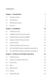
...8 Chapter 2 Installation 10 2.1 Installing the CPU 11 2.2 Installing the CPU Fan and Heatsink 13 2.3 Installing Memory Modules (DIMM) 22 2.4 Expansion Slots (PCI Express Slots) 24 2.5 Jumpers Setup 25 2.6 Onboard Headers and Connectors 26 2.7 M.2_SSD (NGFF) Module Installation Guide (M2_1) 31 2.8... M.2_SSD (NGFF) Module Installation Guide (M2_2) 34 Chapter 3 Software and Utilities Operation 37 3.1 Installing Drivers 37 3.2 ASRock Live Update & APP Shop ...
...8 Chapter 2 Installation 10 2.1 Installing the CPU 11 2.2 Installing the CPU Fan and Heatsink 13 2.3 Installing Memory Modules (DIMM) 22 2.4 Expansion Slots (PCI Express Slots) 24 2.5 Jumpers Setup 25 2.6 Onboard Headers and Connectors 26 2.7 M.2_SSD (NGFF) Module Installation Guide (M2_1) 31 2.8... M.2_SSD (NGFF) Module Installation Guide (M2_2) 34 Chapter 3 Software and Utilities Operation 37 3.1 Installing Drivers 37 3.2 ASRock Live Update & APP Shop ...
User Manual
Page 9
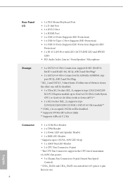
If either one will be disabled. ** Supports NVMe SSD as boot disks ** Supports ASRock U.2 Kit Connector • 1 x COM Port Header • 1 x TPM Header • 1 x Power LED and Speaker Header • 1 x RGB LED Header * Supports up to Gen3 x4 (32 Gb/s) (with Ryzen CPU) or Gen3 x2 (16 Gb/s) ..., 36W LED Strip • 1 x AMD Fan LED Header • 1 x CPU Fan Connector (4-pin) * The CPU Fan Connector supports the CPU fan of them is in use, the other one of maximum 1A (12W) fan power. • 3 x Chassis Fan Connectors (4-pin) (Smart Fan Speed Control) * CHA_FAN2 and CHA_FAN3 can auto ...
If either one will be disabled. ** Supports NVMe SSD as boot disks ** Supports ASRock U.2 Kit Connector • 1 x COM Port Header • 1 x TPM Header • 1 x Power LED and Speaker Header • 1 x RGB LED Header * Supports up to Gen3 x4 (32 Gb/s) (with Ryzen CPU) or Gen3 x2 (16 Gb/s) ..., 36W LED Strip • 1 x AMD Fan LED Header • 1 x CPU Fan Connector (4-pin) * The CPU Fan Connector supports the CPU fan of them is in use, the other one of maximum 1A (12W) fan power. • 3 x Chassis Fan Connectors (4-pin) (Smart Fan Speed Control) * CHA_FAN2 and CHA_FAN3 can auto ...
User Manual
Page 10
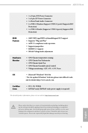
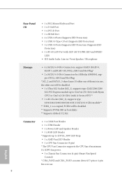
.../Chassis Fan multi-speed control • Voltage monitoring: +12V, +5V, +3.3V, Vcore OS • Microsoft® Windows® 10 64-bit * For the updated Windows® 10 driver, please visit ASRock's web- English 5 AB350 Pro4 • 1 x 24 pin ATX Power Connector • 1 x 8 pin 12V Power Connector • 1 x Front Panel Audio Connector • 2 x USB 2.0 Headers (Support...
.../Chassis Fan multi-speed control • Voltage monitoring: +12V, +5V, +3.3V, Vcore OS • Microsoft® Windows® 10 64-bit * For the updated Windows® 10 driver, please visit ASRock's web- English 5 AB350 Pro4 • 1 x 24 pin ATX Power Connector • 1 x 8 pin 12V Power Connector • 1 x Front Panel Audio Connector • 2 x USB 2.0 Headers (Support...
User Manual
Page 12
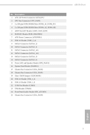
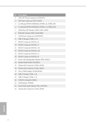
...) 4 2 x 288-pin DDR4 DIMM Slots (DDR4_A2, DDR4_B2) 5 AMD Fan LED Header (AMD_FAN_LED1) 6 RGB LED Header (RGB_HEADER1) 7 ATX Power Connector (ATXPWR1) 8 USB 3.0 Header (USB3_5_6) 9 SATA3 Connector (SATA3_2) 10 SATA3 Connector (SATA3_1) 11 SATA3 Connector...Header (SPK_PLED1) 16 System Panel Header (PANEL1) 17 Chassis Fan Connector (CHA_FAN2) 18 Chassis Fan Connector (CHA_FAN1) 19 Clear CMOS Jumper (CLRCMOS1) 20 USB 2.0 Header (USB_3_4) 21 USB 2.0 Header (USB_1_2) 22 COM Port Header (COM1) 23 TPM Header (TPMS1) 24 Front Panel Audio Header (HD_AUDIO1) 25 Chassis Fan Connector (CHA_FAN3) AB350 Pro4...
...) 4 2 x 288-pin DDR4 DIMM Slots (DDR4_A2, DDR4_B2) 5 AMD Fan LED Header (AMD_FAN_LED1) 6 RGB LED Header (RGB_HEADER1) 7 ATX Power Connector (ATXPWR1) 8 USB 3.0 Header (USB3_5_6) 9 SATA3 Connector (SATA3_2) 10 SATA3 Connector (SATA3_1) 11 SATA3 Connector...Header (SPK_PLED1) 16 System Panel Header (PANEL1) 17 Chassis Fan Connector (CHA_FAN2) 18 Chassis Fan Connector (CHA_FAN1) 19 Clear CMOS Jumper (CLRCMOS1) 20 USB 2.0 Header (USB_3_4) 21 USB 2.0 Header (USB_1_2) 22 COM Port Header (COM1) 23 TPM Header (TPMS1) 24 Front Panel Audio Header (HD_AUDIO1) 25 Chassis Fan Connector (CHA_FAN3) AB350 Pro4...

User Manual
Page 22
Please refer to page 30 for reference only. AB350 Pro4 4 CPU_FAN1 5 RGB LED Cable 4-pin FAN cable CPU_FAN1 +12V AMD_FAN_LED1 *The diagram shown here are for the orientation of AMD Fan LED Header (AMD_FAN_LED1). 17 English
Please refer to page 30 for reference only. AB350 Pro4 4 CPU_FAN1 5 RGB LED Cable 4-pin FAN cable CPU_FAN1 +12V AMD_FAN_LED1 *The diagram shown here are for the orientation of AMD Fan LED Header (AMD_FAN_LED1). 17 English
User Manual
Page 26
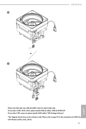
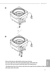
Please refer to page 30 for reference only. AB350 Pro4 6 CPU_FAN1 +12V AMD_FAN_LED1 or 7 CPU_FAN1 AMD_FAN_LED1 USB_5 Please note that only one cable should be used at a time in this step. If you select USB connector, please install AMD utility "SR3 Settings Software". *The diagram shown here are for the orientation of AMD Fan LED Header (AMD_FAN_LED1). 21 English If you select AMD_FAN_LED1, please install ASRock utility "ASRock RGB LED".
Please refer to page 30 for reference only. AB350 Pro4 6 CPU_FAN1 +12V AMD_FAN_LED1 or 7 CPU_FAN1 AMD_FAN_LED1 USB_5 Please note that only one cable should be used at a time in this step. If you select USB connector, please install AMD utility "SR3 Settings Software". *The diagram shown here are for the orientation of AMD Fan LED Header (AMD_FAN_LED1). 21 English If you select AMD_FAN_LED1, please install ASRock utility "ASRock RGB LED".
User Manual
Page 33
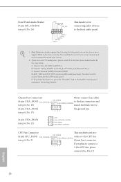
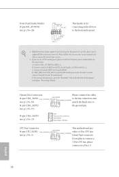
...LIN) to the front audio panel. 1. Front Panel Audio Header (9-pin HD_AUDIO1) (see p.6, No. 24) GND PRESENCE# MIC_RET OUT_RET 1 OUT2_L J_SENSE OUT2_R MIC2_R MIC2_L This header is for connecting audio devices to OUT2_L. If you plan to connect a 3-Pin CPU fan, please connect it to connect them for the HD audio panel... only. You don't need to the front panel audio header by the steps below: A. If you use an AC'97 audio panel, please install it ...
...LIN) to the front audio panel. 1. Front Panel Audio Header (9-pin HD_AUDIO1) (see p.6, No. 24) GND PRESENCE# MIC_RET OUT_RET 1 OUT2_L J_SENSE OUT2_R MIC2_R MIC2_L This header is for connecting audio devices to OUT2_L. If you plan to connect a 3-Pin CPU fan, please connect it to connect them for the HD audio panel... only. You don't need to the front panel audio header by the steps below: A. If you use an AC'97 audio panel, please install it ...

User Manual
Page 35
... be damaged. The cable connection allows users to page 44 for for further instructions on these two headers. RGB LED Header (4-pin RGB_HEADER1) (see p.6, No. 6) AMD FAN LED Header (4-pin AMD_FAN_ LED1) (see p.6, No. 5) RGB LED header is used to connect RGB LED extension cable which allows users to choose from various LED lighting effects...
... be damaged. The cable connection allows users to page 44 for for further instructions on these two headers. RGB LED Header (4-pin RGB_HEADER1) (see p.6, No. 6) AMD FAN LED Header (4-pin AMD_FAN_ LED1) (see p.6, No. 5) RGB LED header is used to connect RGB LED extension cable which allows users to choose from various LED lighting effects...
Quick Installation Guide
Page 4
... (CPU_FAN1) 3 2 x 288-pin DDR4 DIMM Slots (DDR4_A1, DDR4_B1) 4 2 x 288-pin DDR4 DIMM Slots (DDR4_A2, DDR4_B2) 5 AMD Fan LED Header (AMD_FAN_LED1) 6 RGB LED Header (RGB_HEADER1) 7 ATX Power Connector (ATXPWR1) 8 USB 3.0 Header (USB3_5_6) 9 SATA3 Connector (SATA3_2) 10 SATA3 Connector (SATA3_1) 11 SATA3 Connector (SATA3_A1) 12 SATA3 Connector (SATA3_A2) 13 SATA3 Connector (SATA3_3) 14 SATA3 Connector (SATA3_4...
... (CPU_FAN1) 3 2 x 288-pin DDR4 DIMM Slots (DDR4_A1, DDR4_B1) 4 2 x 288-pin DDR4 DIMM Slots (DDR4_A2, DDR4_B2) 5 AMD Fan LED Header (AMD_FAN_LED1) 6 RGB LED Header (RGB_HEADER1) 7 ATX Power Connector (ATXPWR1) 8 USB 3.0 Header (USB3_5_6) 9 SATA3 Connector (SATA3_2) 10 SATA3 Connector (SATA3_1) 11 SATA3 Connector (SATA3_A1) 12 SATA3 Connector (SATA3_A2) 13 SATA3 Connector (SATA3_3) 14 SATA3 Connector (SATA3_4...
Quick Installation Guide
Page 10
... LED Strip • 1 x AMD Fan LED Header • 1 x CPU Fan Connector (4-pin) * The CPU Fan Connector supports the CPU fan of them is occupied, PCIE4 will be disabled. ** Supports NVMe SSD as boot disks ** Supports ASRock U.2 Kit Connector • 1 x COM Port Header • 1 x TPM Header • 1 x Power LED and Speaker Header • 1 x RGB LED Header * Supports up to Gen3 x4...
... LED Strip • 1 x AMD Fan LED Header • 1 x CPU Fan Connector (4-pin) * The CPU Fan Connector supports the CPU fan of them is occupied, PCIE4 will be disabled. ** Supports NVMe SSD as boot disks ** Supports ASRock U.2 Kit Connector • 1 x COM Port Header • 1 x TPM Header • 1 x Power LED and Speaker Header • 1 x RGB LED Header * Supports up to Gen3 x4...
Quick Installation Guide
Page 11
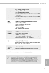
...support • DRAM Voltage multi-adjustment Hardware Monitor • CPU/Chassis temperature sensing • CPU/Chassis Fan Tachometer • CPU/Chassis Quiet Fan • CPU/Chassis Fan multi-speed control • Voltage monitoring: +12V, +5V, +3.3V, Vcore OS • Microsoft...driver, please visit ASRock's web- English 9 It should be done at your system. site for possible damage caused by overclocking. AB350 Pro4 • 1 x 24 pin ATX Power Connector • 1 x 8 pin 12V Power Connector • 1 x Front Panel Audio Connector • 2 x USB 2.0 Headers (Support 4 ...
...support • DRAM Voltage multi-adjustment Hardware Monitor • CPU/Chassis temperature sensing • CPU/Chassis Fan Tachometer • CPU/Chassis Quiet Fan • CPU/Chassis Fan multi-speed control • Voltage monitoring: +12V, +5V, +3.3V, Vcore OS • Microsoft...driver, please visit ASRock's web- English 9 It should be done at your system. site for possible damage caused by overclocking. AB350 Pro4 • 1 x 24 pin ATX Power Connector • 1 x 8 pin 12V Power Connector • 1 x Front Panel Audio Connector • 2 x USB 2.0 Headers (Support 4 ...

Quick Installation Guide
Page 19
Please refer to page 30 for reference only. AB350 Pro4 4 CPU_FAN1 5 RGB LED Cable 4-pin FAN cable CPU_FAN1 +12V AMD_FAN_LED1 *The diagram shown here are for the orientation of AMD Fan LED Header (AMD_FAN_LED1). 17 English
Please refer to page 30 for reference only. AB350 Pro4 4 CPU_FAN1 5 RGB LED Cable 4-pin FAN cable CPU_FAN1 +12V AMD_FAN_LED1 *The diagram shown here are for the orientation of AMD Fan LED Header (AMD_FAN_LED1). 17 English
Quick Installation Guide
Page 23
If you select USB connector, please install AMD utility "SR3 Settings Software". *The diagram shown here are for the orientation of AMD Fan LED Header (AMD_FAN_LED1). 21 English If you select AMD_FAN_LED1, please install ASRock utility "ASRock RGB LED". Please refer to page 30 for reference only. AB350 Pro4 6 CPU_FAN1 +12V AMD_FAN_LED1 or 7 CPU_FAN1 AMD_FAN_LED1 USB_5 Please note that only one cable should be used at a time in this step.
If you select USB connector, please install AMD utility "SR3 Settings Software". *The diagram shown here are for the orientation of AMD Fan LED Header (AMD_FAN_LED1). 21 English If you select AMD_FAN_LED1, please install ASRock utility "ASRock RGB LED". Please refer to page 30 for reference only. AB350 Pro4 6 CPU_FAN1 +12V AMD_FAN_LED1 or 7 CPU_FAN1 AMD_FAN_LED1 USB_5 Please note that only one cable should be used at a time in this step.
Quick Installation Guide
Page 30
... install it to Pin 1-3. MIC_RET and OUT_RET are for connecting audio devices to the front panel audio header by the steps below: A. E. FAN_SPEED (4-pin CPU_FAN1) FAN_VOLTAGE_CONTROL vides a 4-Pin CPU fan GND FAN_SPEED_CONTROL (see p.1, No. 2) (Quiet Fan) connector. To activate the front mic, go to the "FrontMic" Tab in our manual and chassis manual...
... install it to Pin 1-3. MIC_RET and OUT_RET are for connecting audio devices to the front panel audio header by the steps below: A. E. FAN_SPEED (4-pin CPU_FAN1) FAN_VOLTAGE_CONTROL vides a 4-Pin CPU fan GND FAN_SPEED_CONTROL (see p.1, No. 2) (Quiet Fan) connector. To activate the front mic, go to the "FrontMic" Tab in our manual and chassis manual...

Quick Installation Guide
Page 32
...the cable may be damaged. The cable connection allows users to connect RGB LED extension cable that comes with AMD heatsink. AMD FAN LED Header is used to choose from various LED lighting effects. otherwise, the cable may be damaged. Caution: Never install the RGB LED... cable in the wrong orientation; English 30 RGB LED Header (4-pin RGB_HEADER1) (see p.1, No. 6) AMD FAN LED Header (4-pin AMD_FAN_ LED1) (see p.1, No. 5) RGB LED header is used to connect RGB LED extension cable which allows users to choose from various LED ...
...the cable may be damaged. The cable connection allows users to connect RGB LED extension cable that comes with AMD heatsink. AMD FAN LED Header is used to choose from various LED lighting effects. otherwise, the cable may be damaged. Caution: Never install the RGB LED... cable in the wrong orientation; English 30 RGB LED Header (4-pin RGB_HEADER1) (see p.1, No. 6) AMD FAN LED Header (4-pin AMD_FAN_ LED1) (see p.1, No. 5) RGB LED header is used to connect RGB LED extension cable which allows users to choose from various LED ...


