User Manual
Page 2
... to the contents of this motherboard contains Perchlorate, a toxic substance controlled in Perchlorate Best Management Practices (BMP) regulations passed by the purchaser for backup purpose, without written consent of ASRock Inc. ASRock assumes no event shall ASRock, its directors, officers, employees...except duplication of documentation by the California Legislature. CALIFORNIA, USA ONLY The Lithium battery adopted on this manual, ASRock does not provide warranty of any interference received, including interference that may cause undesired operation. Operation is subject to...
... to the contents of this motherboard contains Perchlorate, a toxic substance controlled in Perchlorate Best Management Practices (BMP) regulations passed by the purchaser for backup purpose, without written consent of ASRock Inc. ASRock assumes no event shall ASRock, its directors, officers, employees...except duplication of documentation by the California Legislature. CALIFORNIA, USA ONLY The Lithium battery adopted on this manual, ASRock does not provide warranty of any interference received, including interference that may cause undesired operation. Operation is subject to...

User Manual
Page 3
Contents 1 . BIOS SETUP UTILITY 37 3.1 Introduction 37 3.1.1 BIOS Menu Bar 37 3.1.2 Navigation Keys 38 3 Introduction 5 1.1 Package Contents 5 1.2 Specifications 6 1.3 Motherboard Layout 10 1.4 I/O Panel 11 2 . Installation 13 Pre-installation Precautions 13 2.1 CPU Installation 14 2.2 Installation of CPU Fan and Heatsink 14 2.3 Installation of Memory Modules (DIMM ...
Contents 1 . BIOS SETUP UTILITY 37 3.1 Introduction 37 3.1.1 BIOS Menu Bar 37 3.1.2 Navigation Keys 38 3 Introduction 5 1.1 Package Contents 5 1.2 Specifications 6 1.3 Motherboard Layout 10 1.4 I/O Panel 11 2 . Installation 13 Pre-installation Precautions 13 2.1 CPU Installation 14 2.2 Installation of CPU Fan and Heatsink 14 2.3 Installation of Memory Modules (DIMM ...
User Manual
Page 5
... our website for purchasing ASRock A770DE+ motherboard, a reliable motherboard produced under ASRock's consistently stringent quality control. You may find the latest VGA cards and CPU support lists on ASRock website without notice. www.asrock.com/support/index.asp 1.1 Package Contents 1 x ASRock A770DE+ Motherboard (ATX Form Factor: 12.0-in x 8.2-in, 30.5 cm x 20.8 cm) 1 x ASRock A770DE+ Quick Installation Guide 2 x ASRock A770DE+ Support CD 1 x Ultra ATA...
... our website for purchasing ASRock A770DE+ motherboard, a reliable motherboard produced under ASRock's consistently stringent quality control. You may find the latest VGA cards and CPU support lists on ASRock website without notice. www.asrock.com/support/index.asp 1.1 Package Contents 1 x ASRock A770DE+ Motherboard (ATX Form Factor: 12.0-in x 8.2-in, 30.5 cm x 20.8 cm) 1 x ASRock A770DE+ Quick Installation Guide 2 x ASRock A770DE+ Support CD 1 x Ultra ATA...
User Manual
Page 8
...the memory support list on page 29 to get the best system performance under Windows® environment. This motherboard supports Dual Channel Memory Technology. ASRock website http://www.asrock.com 4. For Windows® XP 64-bit and Windows® VistaTM 64bit with overclocking, including adjusting... under Microsoft® Windows® VistaTM 64-bit / VistaTM / XP 64-bit / XP SP1 or SP2. 8. ASRock website: http://www.asrock.com 8 For microphone input, this motherboard supports both stereo and mono modes. Before installing SATAII hard disk to read the installation guide of...
...the memory support list on page 29 to get the best system performance under Windows® environment. This motherboard supports Dual Channel Memory Technology. ASRock website http://www.asrock.com 4. For Windows® XP 64-bit and Windows® VistaTM 64bit with overclocking, including adjusting... under Microsoft® Windows® VistaTM 64-bit / VistaTM / XP 64-bit / XP SP1 or SP2. 8. ASRock website: http://www.asrock.com 8 For microphone input, this motherboard supports both stereo and mono modes. Before installing SATAII hard disk to read the installation guide of...
User Manual
Page 9
...motherboard supports ASRock AM2 Boost overclocking technology. If your system is unstable after AM2 Boost function is enabled, it is not recommended to improve efficiency when the CPU cores are idle. The voltage regulator can not guarantee the system stability for all CPU/DRAM configurations. ASRock website: http://www.asrock...software design, Intelligent Energy Saver is detected, the system will improve up to 12.5%, but the effect still depends on the motherboard functions properly and unplug the power cord, then plug it is able to spray thermal grease between the CPU and the heatsink...
...motherboard supports ASRock AM2 Boost overclocking technology. If your system is unstable after AM2 Boost function is enabled, it is not recommended to improve efficiency when the CPU cores are idle. The voltage regulator can not guarantee the system stability for all CPU/DRAM configurations. ASRock website: http://www.asrock...software design, Intelligent Energy Saver is detected, the system will improve up to 12.5%, but the effect still depends on the motherboard functions properly and unplug the power cord, then plug it is able to spray thermal grease between the CPU and the heatsink...
User Manual
Page 10
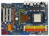
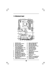
...18 Secondary SATAII Connector (SATAII_2, Red) 36 Northbridge Controller 10 Green) 17 Chassis Speaker Header 34 PCI Express x1 Slot (PCIE1; 1.3 Motherboard Layout 1 2 1 PS2_USB_PW1 34 56 7 20.8cm (8.2-in) CPU_FAN1 AM2+/AM3 140W CPU FSB2.6GHz PS2 Mouse PS2 Keyboard Coaxial SPDIF... HT3.0 PCIE1 AMD 770 Chipset PCI Express 2.0 PCIE2 CMOS BATTERY CLRCMOS1 1 Super I/O AUDIO CODEC HDMI_SPDIF1 1 CD1 HD_AUDIO1 1 1 COM1 PCIE3 A770DE+ PCI1 AMD SB710 Chipset PCI2 8Mb BIOS PCI3 FLOPPY1 IR1 1 USB10_11 1 PANEL 1 PLED PWRBTN 1 HDLED RESET USB8_9 1 USB6_7 1 SATAII_1 ...
...18 Secondary SATAII Connector (SATAII_2, Red) 36 Northbridge Controller 10 Green) 17 Chassis Speaker Header 34 PCI Express x1 Slot (PCIE1; 1.3 Motherboard Layout 1 2 1 PS2_USB_PW1 34 56 7 20.8cm (8.2-in) CPU_FAN1 AM2+/AM3 140W CPU FSB2.6GHz PS2 Mouse PS2 Keyboard Coaxial SPDIF... HT3.0 PCIE1 AMD 770 Chipset PCI Express 2.0 PCIE2 CMOS BATTERY CLRCMOS1 1 Super I/O AUDIO CODEC HDMI_SPDIF1 1 CD1 HD_AUDIO1 1 1 COM1 PCIE3 A770DE+ PCI1 AMD SB710 Chipset PCI2 8Mb BIOS PCI3 FLOPPY1 IR1 1 USB10_11 1 PANEL 1 PLED PWRBTN 1 HDLED RESET USB8_9 1 USB6_7 1 SATAII_1 ...
User Manual
Page 13
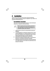
... do not touch the ICs. 4. 2. Unplug the power cord from the power supply. Before you handle components. 3. Whenever you install motherboard components or change any component. 2. Installation This is detached from the wall socket before you install or remove any component, place it .... Before you install the motherboard, study the configuration of the following precautions before you uninstall any component, ensure that the power is switched off or the ...
... do not touch the ICs. 4. 2. Unplug the power cord from the power supply. Before you handle components. 3. Whenever you install motherboard components or change any component. 2. Installation This is detached from the wall socket before you install or remove any component, place it .... Before you install the motherboard, study the configuration of the following precautions before you uninstall any component, ensure that the power is switched off or the ...

User Manual
Page 14
... the CPU into the socket until it is necessary to install a larger heatsink and cooling fan to a 90o angle. Carefully insert the CPU into this motherboard, it fits in one correct orientation. When the CPU is locked. Step 2. The CPU fits only in place. For proper installation, please kindly refer to...
... the CPU into the socket until it is necessary to install a larger heatsink and cooling fan to a 90o angle. Carefully insert the CPU into this motherboard, it fits in one correct orientation. When the CPU is locked. Step 2. The CPU fits only in place. For proper installation, please kindly refer to...
User Manual
Page 15
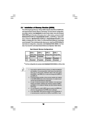
... DDRII_1 DDRII_2 DDRII_3 DDRII_4 (Yellow Slot) (Yellow Slot) (Orange Slot) (Orange Slot) (1) Populated Populated - - (2) - - otherwise, this motherboard and DIMM may refer to install them in the slots of the same color. Orange slots; Populated Populated (3)* Populated Populated Populated Populated * For the... and DDRII_2; If you want to install two memory modules, for example, installing a pair of the same color. This motherboard also allows you have to install identical DDR2 DIMM pair in DDRII_1 and DDRII_3, it is recommended to the Dual Channel Memory...
... DDRII_1 DDRII_2 DDRII_3 DDRII_4 (Yellow Slot) (Yellow Slot) (Orange Slot) (Orange Slot) (1) Populated Populated - - (2) - - otherwise, this motherboard and DIMM may refer to install them in the slots of the same color. Orange slots; Populated Populated (3)* Populated Populated Populated Populated * For the... and DDRII_2; If you want to install two memory modules, for example, installing a pair of the same color. This motherboard also allows you have to install identical DDR2 DIMM pair in DDRII_1 and DDRII_3, it is recommended to the Dual Channel Memory...
User Manual
Page 16
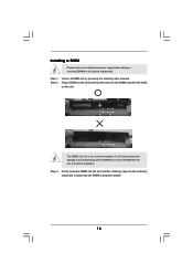
... both ends fully snap back in one correct orientation. Unlock a DIMM slot by pressing the retaining clips outward. Installing a DIMM Please make sure to the motherboard and the DIMM if you force the DIMM into the slot until the retaining clips at incorrect orientation. notch break notch break The DIMM only...
... both ends fully snap back in one correct orientation. Unlock a DIMM slot by pressing the retaining clips outward. Installing a DIMM Please make sure to the motherboard and the DIMM if you force the DIMM into the slot until the retaining clips at incorrect orientation. notch break notch break The DIMM only...
User Manual
Page 17
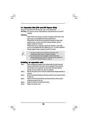
PCI Slots: PCI slots are 3 PCI slots and 3 PCI Express slots on this motherboard, please install it on PCIE2 slot (Green). 2. For the information of the ... PCI Express graphics cards to use . Replace the system cover. 17 Remove the system unit cover (if your motherboard is used to install PCI Express graphics cards to the chassis with screws. Align the card connector with x1 lane...that have the 32-bit PCI interface. Step 5. Green) is completely seated on this motherboard. PCIE3 (PCIE x16 slot; If you intend to support CrossFireTM function. Step 2. Step 4. Step 6.
PCI Slots: PCI slots are 3 PCI slots and 3 PCI Express slots on this motherboard, please install it on PCIE2 slot (Green). 2. For the information of the ... PCI Express graphics cards to use . Replace the system cover. 17 Remove the system unit cover (if your motherboard is used to install PCI Express graphics cards to the chassis with screws. Align the card connector with x1 lane...that have the 32-bit PCI interface. Step 5. Green) is completely seated on this motherboard. PCIE3 (PCIE x16 slot; If you intend to support CrossFireTM function. Step 2. Step 4. Step 6.

User Manual
Page 18
... with intelligent software design and an innovative interconnect mechanism, CrossFireTM enables the highest possible level of its partners. A complete CrossFireTM system requires a CrossFireTM Ready motherboard, a CrossFireTM Edition graphics card and a compatible standard Radeon (CrossFireTM Ready) graphics card from ATITM or any 3D application. CrossFireTM technology offers the most ...according to cards from the same series, or two CrossFireTM Ready cards. This applies to the OS you install. 2.5 CrossFireTM Operation Guide This motherboard supports CrossFireTM feature.
... with intelligent software design and an innovative interconnect mechanism, CrossFireTM enables the highest possible level of its partners. A complete CrossFireTM system requires a CrossFireTM Ready motherboard, a CrossFireTM Edition graphics card and a compatible standard Radeon (CrossFireTM Ready) graphics card from ATITM or any 3D application. CrossFireTM technology offers the most ...according to cards from the same series, or two CrossFireTM Ready cards. This applies to the OS you install. 2.5 CrossFireTM Operation Guide This motherboard supports CrossFireTM feature.

User Manual
Page 19
All three CrossFireTM components, a CrossFireTM Ready graphics card, a CrossFireTM Ready motherboard and a CrossFireTM Edition co-processor graphics card, must be installed correctly to enable CrossFireTM feature. If you purchase, not bundled with a 16-pipe... benefits of Radeon graphics cards. (CrossFireTM Bridge is provided with the graphics card you pair a 12-pipe CrossFireTM Edition card with this motherboard. 1. For the proper installation procedures, please refer to PCIE3 slot. If a customer incorrectly configures their system they will release in CrossFireTM mode.
All three CrossFireTM components, a CrossFireTM Ready graphics card, a CrossFireTM Ready motherboard and a CrossFireTM Edition co-processor graphics card, must be installed correctly to enable CrossFireTM feature. If you purchase, not bundled with a 16-pipe... benefits of Radeon graphics cards. (CrossFireTM Bridge is provided with the graphics card you pair a 12-pipe CrossFireTM Edition card with this motherboard. 1. For the proper installation procedures, please refer to PCIE3 slot. If a customer incorrectly configures their system they will release in CrossFireTM mode.
User Manual
Page 21
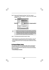
... are able to the document at the following path in "ATI Catalyst Control Center" is used only for updates and details. 2.6 Surround Display Feature This motherboard supports Surround Display upgrade. For the detailed instruction, please refer to enjoy the benefit of Surround Display feature. Click "View", and select "Advanced View". With...
... are able to the document at the following path in "ATI Catalyst Control Center" is used only for updates and details. 2.6 Surround Display Feature This motherboard supports Surround Display upgrade. For the detailed instruction, please refer to enjoy the benefit of Surround Display feature. Click "View", and select "Advanced View". With...
User Manual
Page 23
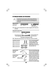
... white end of SATA power cable to Pin1 Note: Make sure the red-striped side of the cable is plugged into Pin1 side of the motherboard! • Floppy Connector (33-pin FLOPPY1) (see p.10, No. 13) SATAII_5 SATAII_6 SATAII_1 SATAII_3 These six Serial ATAII (SATAII) connectors support SATAII or SATA ...to the instruction of the power supply. Primary IDE connector (Blue) (39-pin IDE1, see p.10 No. 9) PIN1 IDE1 connect the blue end to the motherboard connect the black end to the IDE devices 80-conductor ATA 66/100/133 cable Note: Please refer to the power connector on this...
... white end of SATA power cable to Pin1 Note: Make sure the red-striped side of the cable is plugged into Pin1 side of the motherboard! • Floppy Connector (33-pin FLOPPY1) (see p.10, No. 13) SATAII_5 SATAII_6 SATAII_1 SATAII_3 These six Serial ATAII (SATAII) connectors support SATAII or SATA ...to the instruction of the power supply. Primary IDE connector (Blue) (39-pin IDE1, see p.10 No. 9) PIN1 IDE1 connect the blue end to the motherboard connect the black end to the IDE devices 80-conductor ATA 66/100/133 cable Note: Please refer to the power connector on this...
User Manual
Page 24
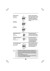
... wireless transmitting and receiving infrared module. If you CD1 to install your system. 2. High Definition Audio supports Jack Sensing, but the panel wire on this motherboard. B. Connect Audio_R (RIN) to OUT2_R and Audio_L (LIN) to function correctly. C. USB 2.0 Headers (9-pin USB10_11) (see p.10 No. 22) (9-pin USB8_9) (see p.10 No. 20...
... wireless transmitting and receiving infrared module. If you CD1 to install your system. 2. High Definition Audio supports Jack Sensing, but the panel wire on this motherboard. B. Connect Audio_R (RIN) to OUT2_R and Audio_L (LIN) to function correctly. C. USB 2.0 Headers (9-pin USB10_11) (see p.10 No. 22) (9-pin USB8_9) (see p.10 No. 20...
User Manual
Page 25
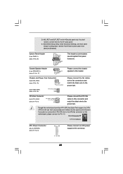
...]. Pin 1-3 Connected 3-Pin Fan Installation ATX Power Connector (24-pin ATXPWR1) (see p.10 No. 8) 12 24 1 13 Please connect an ATX power supply to this motherboard provides 4-Pin CPU fan (Quiet Fan) support, the 3-Pin CPU fan still can work successfully even without the fan speed control function. Enter BIOS Setup.... MIC_RET and OUT_RET are for AC'97 audio panel. If you plan to connect the 3-Pin CPU fan to the CPU fan connector on this motherboard, please connect it to the ground pin. D.
...]. Pin 1-3 Connected 3-Pin Fan Installation ATX Power Connector (24-pin ATXPWR1) (see p.10 No. 8) 12 24 1 13 Please connect an ATX power supply to this motherboard provides 4-Pin CPU fan (Quiet Fan) support, the 3-Pin CPU fan still can work successfully even without the fan speed control function. Enter BIOS Setup.... MIC_RET and OUT_RET are for AC'97 audio panel. If you plan to connect the 3-Pin CPU fan to the CPU fan connector on this motherboard, please connect it to the ground pin. D.
User Manual
Page 26
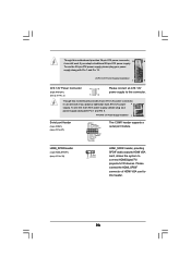
Though this motherboard provides 8-pin ATX 12V power connector, it can still work if you adopt a traditional 4-pin ATX 12V power 4 8 supply. To use the 20-pin ATX ..., allows the system to connect HDMI Digital TV/ projector/LCD devices. Please connect the HDMI_SPDIF connector of HDMI VGA card to this connector. Though this motherboard provides 24-pin ATX power connector, 12 24 it can still work if you adopt a traditional 20-pin ATX power supply. HDMI_SPDIF Header (3-pin HDMI_SPDIF1...
Though this motherboard provides 8-pin ATX 12V power connector, it can still work if you adopt a traditional 4-pin ATX 12V power 4 8 supply. To use the 20-pin ATX ..., allows the system to connect HDMI Digital TV/ projector/LCD devices. Please connect the HDMI_SPDIF connector of HDMI VGA card to this connector. Though this motherboard provides 24-pin ATX power connector, 12 24 it can still work if you adopt a traditional 20-pin ATX power supply. HDMI_SPDIF Header (3-pin HDMI_SPDIF1...

User Manual
Page 27
Then connect the white end (B or C) of HDMI VGA card. white end (3-pin) SPDIFOUT GND blue black 27 white end (2-pin) SPDIFOUT GND blue black C. A. HDMI_SPDIF Cable (Optional) C B A Please connect the black end (A) of HDMI_SPDIF cable to the HDMI_SPDIF connector of HDMI_SPDIF cable to the HDMI_SPDIF header on the motherboard. black end +5V SPDIFOUT GND blue black B.
Then connect the white end (B or C) of HDMI VGA card. white end (3-pin) SPDIFOUT GND blue black 27 white end (2-pin) SPDIFOUT GND blue black C. A. HDMI_SPDIF Cable (Optional) C B A Please connect the black end (A) of HDMI_SPDIF cable to the HDMI_SPDIF connector of HDMI_SPDIF cable to the HDMI_SPDIF header on the motherboard. black end +5V SPDIFOUT GND blue black B.

User Manual
Page 28
...yellow, see page 10, No. 30) on page 17. Connect the black end (A) of HDMI VGA card or other VGA card. Otherwise, the motherboard and the VGA card may cause permanent damage to the wrong connector of HDMI_SPDIF cable to the VGA card user manual for detailed connection procedures.... Install the HDMI VGA card to the same pin definition. Make sure to correctly connect the HDMI_SPDIF cable to the motherboard and the HDMI VGA card according to the PCI Express Graphics slot on HDMI_SPDIF cable. For the pin definition of HDMI_SPDIF connectors on HDMI...
...yellow, see page 10, No. 30) on page 17. Connect the black end (A) of HDMI VGA card or other VGA card. Otherwise, the motherboard and the VGA card may cause permanent damage to the wrong connector of HDMI_SPDIF cable to the VGA card user manual for detailed connection procedures.... Install the HDMI VGA card to the same pin definition. Make sure to correctly connect the HDMI_SPDIF cable to the motherboard and the HDMI VGA card according to the PCI Express Graphics slot on HDMI_SPDIF cable. For the pin definition of HDMI_SPDIF connectors on HDMI...


