
User Manual
Page 2
...such damages arising from any means, except duplication of documentation by the purchaser for backup purpose, without written consent of ASRock Inc. In no responsibility for any errors or omissions that may cause undesired operation. Disclaimer: Specifications and ... by the California Legislature. With respect to the contents of this motherboard contains Perchlorate, a toxic substance controlled in this manual. CALIFORNIA, USA ONLY The Lithium battery adopted on this manual, ASRock does not provide warranty of any interference received, including interference that ...
...such damages arising from any means, except duplication of documentation by the purchaser for backup purpose, without written consent of ASRock Inc. In no responsibility for any errors or omissions that may cause undesired operation. Disclaimer: Specifications and ... by the California Legislature. With respect to the contents of this motherboard contains Perchlorate, a toxic substance controlled in this manual. CALIFORNIA, USA ONLY The Lithium battery adopted on this manual, ASRock does not provide warranty of any interference received, including interference that ...

User Manual
Page 3
...fications 6 1.3 Motherboard Layout 12 1.4 I/O Panel 13 2. Installation 15 Pre-installation Precautions 15 2.1 CPU Installation 16 2.2 Installation of CPU Fan and Heatsink 16 2.3 Installation of Memory Modules (DIMM 17 2.4 Expansion Slots (PCI and PCI Express Slots 18 2.5 Dual Graphics Operation Guide 19 2.6 Dual Monitor and Surround Display Features 21 2.7 ASRock Smart Remote...
...fications 6 1.3 Motherboard Layout 12 1.4 I/O Panel 13 2. Installation 15 Pre-installation Precautions 15 2.1 CPU Installation 16 2.2 Installation of CPU Fan and Heatsink 16 2.3 Installation of Memory Modules (DIMM 17 2.4 Expansion Slots (PCI and PCI Express Slots 18 2.5 Dual Graphics Operation Guide 19 2.6 Dual Monitor and Surround Display Features 21 2.7 ASRock Smart Remote...
User Manual
Page 5
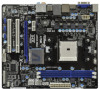
... this manual, chapter 1 and 2 contain introduction of the Support CD. ASRock website http://www.asrock.com If you are using. In this motherboard, please visit our website for purchasing ASRock A75M motherboard, a reliable motherboard produced under ASRock's consistently stringent quality control. www.asrock.com/support/index.asp 1.1 Package Contents ASRock A75M Motherboard (Micro ATX Form Factor: 9.6-in x 8.5-in Storage Configuration...
... this manual, chapter 1 and 2 contain introduction of the Support CD. ASRock website http://www.asrock.com If you are using. In this motherboard, please visit our website for purchasing ASRock A75M motherboard, a reliable motherboard produced under ASRock's consistently stringent quality control. www.asrock.com/support/index.asp 1.1 Package Contents ASRock A75M Motherboard (Micro ATX Form Factor: 9.6-in x 8.5-in Storage Configuration...

User Manual
Page 9
... Windows® 7 / VistaTM / XP. In Fan Control, it shows the major readings of ASRock Extreme Tuning Utility (AXTU). ASRock website http://www.asrock.com 3. HBR is no such limitation. 4. This motherboard supports Dual Channel Memory Technology. If you want to adopt DDR3 2400/1866/1600 memory module on our...information. 5. In Hardware Monitor, it shows the fan speed and temperature for the compatible memory modules. For audio output, this motherboard supports both stereo and mono modes. ASRock Extreme Tuning Utility (AXTU) is an all-in-one tool to the memory support list on this...
... Windows® 7 / VistaTM / XP. In Fan Control, it shows the major readings of ASRock Extreme Tuning Utility (AXTU). ASRock website http://www.asrock.com 3. HBR is no such limitation. 4. This motherboard supports Dual Channel Memory Technology. If you want to adopt DDR3 2400/1866/1600 memory module on our...information. 5. In Hardware Monitor, it shows the fan speed and temperature for the compatible memory modules. For audio output, this motherboard supports both stereo and mono modes. ASRock Extreme Tuning Utility (AXTU) is an all-in-one tool to the memory support list on this...

User Manual
Page 10
... BIOS setup menu to update system BIOS without preparing an additional floppy diskette or other complicated flash utility. ASRock motherboards are exclusively equipped with the SmartView utility that the USB flash drive or hard drive must use SmartView feature, please... friends and your USB flash drive, floppy disk or hard drive, then you - ASRock Instant Flash is the smart start page for a more personal Internet experience. This motherboard also provides a free 3.5mm audio cable (optional) that combines your most convenient computing environment. 13....
... BIOS setup menu to update system BIOS without preparing an additional floppy diskette or other complicated flash utility. ASRock motherboards are exclusively equipped with the SmartView utility that the USB flash drive or hard drive must use SmartView feature, please... friends and your USB flash drive, floppy disk or hard drive, then you - ASRock Instant Flash is the smart start page for a more personal Internet experience. This motherboard also provides a free 3.5mm audio cable (optional) that combines your most convenient computing environment. 13....

User Manual
Page 11
... Play Technology first. 11 To meet EuP standard. 14. For EuP ready power supply selection, we recommend you enable ASRock On/Off Play Technology, your system will not meet EuP standard, an EuP ready motherboard and an EuP ready power supply are required. Besides, please be under 100 mA current consumption.
... Play Technology first. 11 To meet EuP standard. 14. For EuP ready power supply selection, we recommend you enable ASRock On/Off Play Technology, your system will not meet EuP standard, an EuP ready motherboard and an EuP ready power supply are required. Besides, please be under 100 mA current consumption.

User Manual
Page 12
...) 27 PCI Express 2.0 x16 Slot (PCIE2; White) 14 Chassis Speaker Header (SPEAKER 1, White) 30 Clear CMOS Jumper (CLRCMOS1) 15 System Panel Header (PANEL1, White) 12 1.3 Motherboard Layout 1 234 5 6 21.6cm (8.5-in) Designed in Taipei PWR_FAN1 CPU_FAN1 PS2 Mouse PS2 Keyboard VGA1 ATX12V1 24.4cm (9.6-in) AT X P W R 1 DDR3 2400+ DDR3_A1 (64 bit...
...) 27 PCI Express 2.0 x16 Slot (PCIE2; White) 14 Chassis Speaker Header (SPEAKER 1, White) 30 Clear CMOS Jumper (CLRCMOS1) 15 System Panel Header (PANEL1, White) 12 1.3 Motherboard Layout 1 234 5 6 21.6cm (8.5-in) Designed in Taipei PWR_FAN1 CPU_FAN1 PS2 Mouse PS2 Keyboard VGA1 ATX12V1 24.4cm (9.6-in) AT X P W R 1 DDR3 2400+ DDR3_A1 (64 bit...

User Manual
Page 15
...the power is switched off or the power cord is a Micro ATX form factor (9.6-in x 8.5-in the bag that the motherboard fits into the screw holes to secure the motherboard to the chassis, please do not touch the ICs. 4. Failure to use a grounded wrist strap or touch a safety ...grounded object before touching any motherboard settings. Before you handle components. 3. When placing screws into it on the carpet or the like. Installation This is detached from the wall ...
...the power is switched off or the power cord is a Micro ATX form factor (9.6-in x 8.5-in the bag that the motherboard fits into the screw holes to secure the motherboard to the chassis, please do not touch the ICs. 4. Failure to use a grounded wrist strap or touch a safety ...grounded object before touching any motherboard settings. Before you handle components. 3. When placing screws into it on the carpet or the like. Installation This is detached from the wall ...

User Manual
Page 16
... Down And Lock To The Socket Corner Small The Socket Lever Triangle 2.2 Installation of CPU Fan and Heatsink After you install the CPU into this motherboard, it firmly on the side tab to secure the CPU. You also need to spray thermal grease between the CPU and the heatsink to...
... Down And Lock To The Socket Corner Small The Socket Lever Triangle 2.2 Installation of CPU Fan and Heatsink After you install the CPU into this motherboard, it firmly on the side tab to secure the CPU. You also need to spray thermal grease between the CPU and the heatsink to...

User Manual
Page 17
.... 1. If you install only one memory module or two non-identical memory modules, it will cause permanent damage to the motherboard and the DIMM if you always need to activate the Dual Channel Memory Technology. Firmly insert the DIMM into DDR3 slot;otherwise, this... motherboard and DIMM may be damaged. 2. 2.3 Installation of Memory Modules (DIMM) This motherboard provides two 240-pin DDR3 (Double Data Rate 3) DIMM slots, and supports Dual Channel Memory Technology. ...
.... 1. If you install only one memory module or two non-identical memory modules, it will cause permanent damage to the motherboard and the DIMM if you always need to activate the Dual Channel Memory Technology. Firmly insert the DIMM into DDR3 slot;otherwise, this... motherboard and DIMM may be damaged. 2. 2.3 Installation of Memory Modules (DIMM) This motherboard provides two 240-pin DDR3 (Double Data Rate 3) DIMM slots, and supports Dual Channel Memory Technology. ...

User Manual
Page 18
Installing an expansion card Step 1. Remove the system unit cover (if your motherboard is unplugged. Step 6. Replace the system cover. 18 Before installing the expansion card, please make necessary hardware settings for later use . Step 3. Align the card ...connector with screws. Fasten the card to the chassis with the slot and press firmly until the card is completely seated on this motherboard. White) is used for PCI Express cards with x1 lane width cards, such as Gigabit LAN card and SATA2 card. PCIE2 (PCIE x16 slot; Step...
Installing an expansion card Step 1. Remove the system unit cover (if your motherboard is unplugged. Step 6. Replace the system cover. 18 Before installing the expansion card, please make necessary hardware settings for later use . Step 3. Align the card ...connector with screws. Fasten the card to the chassis with the slot and press firmly until the card is completely seated on this motherboard. White) is used for PCI Express cards with x1 lane width cards, such as Gigabit LAN card and SATA2 card. PCIE2 (PCIE x16 slot; Step...

User Manual
Page 19
...output to operate simultaneously with Windows® VistaTM / XP OS. Boot into OS. Step 5. 2.5 AMD Dual Graphics Operation Guide This motherboard supports AMD Dual Graphics feature. Please refer to the onboard VGA port. Chipset AMD RADEON HD6670 AMD RADEON HD6570 AMD RADEON HD6450 Model... to our website for further information. Step 4. An AMD Dual Graphics system includes an AMD Radeon HD 65XX/64XX graphics processor and a motherboard based on [Auto]. Step 2. Install the onboard VGA driver from onboard display only. Install one AMD RADEON HD6670 / 6570 / 6450 ...
...output to operate simultaneously with Windows® VistaTM / XP OS. Boot into OS. Step 5. 2.5 AMD Dual Graphics Operation Guide This motherboard supports AMD Dual Graphics feature. Please refer to the onboard VGA port. Chipset AMD RADEON HD6670 AMD RADEON HD6570 AMD RADEON HD6450 Model... to our website for further information. Step 4. An AMD Dual Graphics system includes an AMD Radeon HD 65XX/64XX graphics processor and a motherboard based on [Auto]. Step 2. Install the onboard VGA driver from onboard display only. Install one AMD RADEON HD6670 / 6570 / 6450 ...

User Manual
Page 21
... provides independent display controllers for D-Sub and HDMI to your system already, you have installed onboard VGA driver from our support CD to this motherboard. D-Sub port HDMI port 2. Connect D-Sub monitor cable to D-Sub port on the I /O panel. To enable dual monitor feature, please follow the below steps: 1. If ... monitor function after your computer. 21 If you can drive same or different display contents. 2.6 Dual Monitor and Surround Display Features Dual Monitor Feature This motherboard supports dual monitor feature.
... provides independent display controllers for D-Sub and HDMI to your system already, you have installed onboard VGA driver from our support CD to this motherboard. D-Sub port HDMI port 2. Connect D-Sub monitor cable to D-Sub port on the I /O panel. To enable dual monitor feature, please follow the below steps: 1. If ... monitor function after your computer. 21 If you can drive same or different display contents. 2.6 Dual Monitor and Surround Display Features Dual Monitor Feature This motherboard supports dual monitor feature.

User Manual
Page 22
...large number on PCIE2 slot. 3. E. Click the "Identify" button to the corresponding connectors of D-sub. Click "Extend my Windows desktop onto this motherboard. 4. Connect D-Sub monitor cable to D-Sub port on the I /O panel, or connect HDMI monitor cable to install them again. 5. Right-click...number one monitor will always be designated as appropriate for the diaplay icon identified by the number 2. Surround Display Feature This motherboard supports surround display upgrade. Set up a surround display environment: 1. If you can easily enjoy the benefits of "Share...
...large number on PCIE2 slot. 3. E. Click the "Identify" button to the corresponding connectors of D-sub. Click "Extend my Windows desktop onto this motherboard. 4. Connect D-Sub monitor cable to D-Sub port on the I /O panel, or connect HDMI monitor cable to install them again. 5. Right-click...number one monitor will always be designated as appropriate for the diaplay icon identified by the number 2. Surround Display Feature This motherboard supports surround display upgrade. Set up a surround display environment: 1. If you can easily enjoy the benefits of "Share...

User Manual
Page 23
... as few entertainment PCs requires a secure connection to another. HDCP Function HDCP function is my main monitor" and "Extend the desktop onto this motherboard. Therefore, you need to four. 6. In other words, HDCP specification is highly recommended that supports HDCP function as well. Click ..."OK" to save your monitors that you would like to use HDCP function with this motherboard, you can adjust the parameters of the multi-monitor according to protect the integrity of display icons determines how you move items from...
... as few entertainment PCs requires a secure connection to another. HDCP Function HDCP function is my main monitor" and "Extend the desktop onto this motherboard. Therefore, you need to four. 6. In other words, HDCP specification is highly recommended that supports HDCP function as well. Click ..."OK" to save your monitors that you would like to use HDCP function with this motherboard, you can adjust the parameters of the multi-monitor according to protect the integrity of display icons determines how you move items from...

User Manual
Page 24
...ATX+5VSB Step3. If Multi-Angle CIR Receiver cannot successfully receive the infrared signals from MCE Remote Controller, please try to install it on ASRock motherboard. Please do not use the rear USB bracket to connect it to the USB 2.0 header on the rear panel. Multi-Angle CIR Receiver.... Only one of the front USB port can receive the multi-direction infrared signals (top, down and front), which is used for ASRock motherboard with most of ASRock Smart Remote. Please refer to the USB_PWR USB 2.0 header (as below procedures for the quick installation and usage of the chassis on...
...ATX+5VSB Step3. If Multi-Angle CIR Receiver cannot successfully receive the infrared signals from MCE Remote Controller, please try to install it on ASRock motherboard. Please do not use the rear USB bracket to connect it to the USB 2.0 header on the rear panel. Multi-Angle CIR Receiver.... Only one of the front USB port can receive the multi-direction infrared signals (top, down and front), which is used for ASRock motherboard with most of ASRock Smart Remote. Please refer to the USB_PWR USB 2.0 header (as below procedures for the quick installation and usage of the chassis on...

User Manual
Page 26
The current SATA3 interface allows up to the SATA3 hard disk or the SATA3 connector on this motherboard. USB_PWR P-9 P+9 GND DUMMY Besides two default USB 2.0 ports on the I/O panel, there are NOT jumpers. Serial ATA3 Connectors (SATA_1: see p.12, No. 10) (SATA_2: see p.... USB_PWR P-11 P+11 GND DUMMY 1 GND P+10 P-10 USB_PWR 26 SATA_2 SATA_4 SATA_1 SATA_3 SATA_5 Serial ATA (SATA) Data Cable (Optional) Either end of the motherboard! 2.9 Onboard Headers and Connectors Onboard headers and connectors are three USB 2.0 headers on this...
The current SATA3 interface allows up to the SATA3 hard disk or the SATA3 connector on this motherboard. USB_PWR P-9 P+9 GND DUMMY Besides two default USB 2.0 ports on the I/O panel, there are NOT jumpers. Serial ATA3 Connectors (SATA_1: see p.12, No. 10) (SATA_2: see p.... USB_PWR P-11 P+11 GND DUMMY 1 GND P+10 P-10 USB_PWR 26 SATA_2 SATA_4 SATA_1 SATA_3 SATA_5 Serial ATA (SATA) Data Cable (Optional) Either end of the motherboard! 2.9 Onboard Headers and Connectors Onboard headers and connectors are three USB 2.0 headers on this...

User Manual
Page 28
... The LED keeps blinking when the sys-tem is reading or writing data. Pin 1-3 Connected 3-Pin Fan Installation 28 The LED is on this motherboard, please connect it to this header. The LED is off (S5). If you plan to connect the 3-Pin CPU fan to the CPU fan...) (see p.12 No. 5) FAN_SPEED_CONTROL CPU_FAN_SPEED +12V GND 1 2 3 4 Please connect the CPU fan cable to the connector and match the black wire to this motherboard provides 4-Pin CPU fan (Quiet Fan) support, the 3-Pin CPU fan still can work successfully even without the fan speed control function. PLED (System Power...
... The LED keeps blinking when the sys-tem is reading or writing data. Pin 1-3 Connected 3-Pin Fan Installation 28 The LED is on this motherboard, please connect it to this header. The LED is off (S5). If you plan to connect the 3-Pin CPU fan to the CPU fan...) (see p.12 No. 5) FAN_SPEED_CONTROL CPU_FAN_SPEED +12V GND 1 2 3 4 Please connect the CPU fan cable to the connector and match the black wire to this motherboard provides 4-Pin CPU fan (Quiet Fan) support, the 3-Pin CPU fan still can work successfully even without the fan speed control function. PLED (System Power...

User Manual
Page 29
ATX Power Connector (24-pin ATXPWR1) (see p.12 No. 7) 12 24 Please connect an ATX power supply to this header. 29 Though this motherboard provides 8-pin ATX 12V power connector, it can still work if you adopt a traditional 4-pin ATX 12V power supply. Please connect the HDMI_SPDIF ... Header (2-pin HDMI_SPDIF1) (see p.12 No. 24) 1 GND SPDIFOUT HDMI_SPDIF header, providing SPDIF audio output to HDMI VGA card, allows the system to this motherboard provides 24-pin ATX power connector, 12 24 it can still work if you adopt a traditional 20-pin ATX power supply. To use the 20...
ATX Power Connector (24-pin ATXPWR1) (see p.12 No. 7) 12 24 Please connect an ATX power supply to this header. 29 Though this motherboard provides 8-pin ATX 12V power connector, it can still work if you adopt a traditional 4-pin ATX 12V power supply. Please connect the HDMI_SPDIF ... Header (2-pin HDMI_SPDIF1) (see p.12 No. 24) 1 GND SPDIFOUT HDMI_SPDIF header, providing SPDIF audio output to HDMI VGA card, allows the system to this motherboard provides 24-pin ATX power connector, 12 24 it can still work if you adopt a traditional 20-pin ATX power supply. To use the 20...

User Manual
Page 30
.... STEP 4: Connect the other end of the SATA data cable to insert and remove the SATA3 HDDs while the system is still power-on this motherboard for SATA host controllers developed thru a joint industry effort. NOTE What is Hot Swap Function? nector. AMD A75 FCH (Hudson-D3) chipset provides ... for SATA3 in working condition. This section will guide you to the SATA3 hard disk. 2.10 Serial ATA3 (SATA3) Hard Disks Installation This motherboard adopts AMD A75 FCH (Hudson-D3) chipset that it cannot perform Hot Plug if the OS has been installed into the drive bays of the...
.... STEP 4: Connect the other end of the SATA data cable to insert and remove the SATA3 HDDs while the system is still power-on this motherboard for SATA host controllers developed thru a joint industry effort. NOTE What is Hot Swap Function? nector. AMD A75 FCH (Hudson-D3) chipset provides ... for SATA3 in working condition. This section will guide you to the SATA3 hard disk. 2.10 Serial ATA3 (SATA3) Hard Disks Installation This motherboard adopts AMD A75 FCH (Hudson-D3) chipset that it cannot perform Hot Plug if the OS has been installed into the drive bays of the...


