
User Manual
Page 1
All rights reserved. 1 A75M User Manual Version 1.1 Published June 2011 Copyright©2011 ASRock INC.
All rights reserved. 1 A75M User Manual Version 1.1 Published June 2011 Copyright©2011 ASRock INC.

User Manual
Page 2
...this device may not cause harmful interference, and (2) this device must accept any defect or error in the manual or product. With respect to the contents of this manual, ASRock does not provide warranty of any means, except duplication of documentation by the purchaser for backup purpose, without... written consent of ASRock Inc. Products and corporate names appearing in this manual may or may not be registered trademarks ...
...this device may not cause harmful interference, and (2) this device must accept any defect or error in the manual or product. With respect to the contents of this manual, ASRock does not provide warranty of any means, except duplication of documentation by the purchaser for backup purpose, without... written consent of ASRock Inc. Products and corporate names appearing in this manual may or may not be registered trademarks ...
User Manual
Page 5
... the BIOS setup, please refer to quality and endurance. It delivers excellent performance with robust design conforming to ASRock's commitment to the "User Manual" in our support CD for purchasing ASRock A75M motherboard, a reliable motherboard produced under ASRock's consistently stringent quality control. To get better performance in Windows® 7 / 7 64-bit / VistaTM / VistaTM 64 bit...
... the BIOS setup, please refer to quality and endurance. It delivers excellent performance with robust design conforming to ASRock's commitment to the "User Manual" in our support CD for purchasing ASRock A75M motherboard, a reliable motherboard produced under ASRock's consistently stringent quality control. To get better performance in Windows® 7 / 7 64-bit / VistaTM / VistaTM 64 bit...

User Manual
Page 16
... lever clicks on the socket while you install the CPU into the socket to secure the CPU. Then connect the CPU fan to the instruction manuals of the pins. For proper installation, please kindly refer to the CPU FAN connector (CPU_FAN1, see Page 12, No. 5). DO NOT force the CPU into...
... lever clicks on the socket while you install the CPU into the socket to secure the CPU. Then connect the CPU fan to the instruction manuals of the pins. For proper installation, please kindly refer to the CPU FAN connector (CPU_FAN1, see Page 12, No. 5). DO NOT force the CPU into...

User Manual
Page 27
.... Note the positive and negative pins before connecting the cables. Connect Audio_R (RIN) to OUT2_R and Audio_L (LIN) to the "FrontMic" Tab in our manual and chassis manual to MIC2_L. PWRBTN (Power Switch): Connect to connect the remote controller receiver. B. Infrared Module Header (5-pin IR1) (see p.12 No. 19) IRTX +5VSB DUMMY...
.... Note the positive and negative pins before connecting the cables. Connect Audio_R (RIN) to OUT2_R and Audio_L (LIN) to the "FrontMic" Tab in our manual and chassis manual to MIC2_L. PWRBTN (Power Switch): Connect to connect the remote controller receiver. B. Infrared Module Header (5-pin IR1) (see p.12 No. 19) IRTX +5VSB DUMMY...

User Manual
Page 31
... data loss. Make sure to power supply 1. Below operation procedure is designed only for SATA3 HDD in the product spec on our support website: www.asrock.com 4. A. 7-pin SATA data cable B. Without SATA 15-pin power connector interface, the SATA3 Hot Plug cannot be damaged under the Hot Plug ...operation. 3. Make sure your dealer or HDD user manual. Even some SATA3 HDDs provide both SATA 15-pin power connector and IDE 1x4-pin conventional power connector interfaces, the IDE 1x4-pin conventional...
... data loss. Make sure to power supply 1. Below operation procedure is designed only for SATA3 HDD in the product spec on our support website: www.asrock.com 4. A. 7-pin SATA data cable B. Without SATA 15-pin power connector interface, the SATA3 Hot Plug cannot be damaged under the Hot Plug ...operation. 3. Make sure your dealer or HDD user manual. Even some SATA3 HDDs provide both SATA 15-pin power connector and IDE 1x4-pin conventional power connector interfaces, the IDE 1x4-pin conventional...

User Manual
Page 39
..., it is set to [Auto] by default. Multiplier/Voltage Change This item is set up overclocking features. CPU Voltage It allows you can set to [Manual], you adopt supports this to select enable or disable AMD Turbo Core Technology. Configuration options: [Auto] and [Disabled]. However, for reference. Use this...
..., it is set to [Auto] by default. Multiplier/Voltage Change This item is set up overclocking features. CPU Voltage It allows you can set to [Manual], you adopt supports this to select enable or disable AMD Turbo Core Technology. Configuration options: [Auto] and [Disabled]. However, for reference. Use this...

User Manual
Page 40
...on the same node, or accross nodes, decreasing access contention. Bank Interleaving Interleaving allows memory accesses to change Write Recovery Time (tWR) Auto/Manual setting. The default is [Auto]. The default is [Auto]. Configuration options: [Disabled], [Auto]. The default is [Auto]. ...mode. DRAM Timing Control Power Down Enable Use this item to change Command Rate (CR) Auto/Manual setting. Channel Interleaving It allows you to change CAS# Latency (tCL) Auto/Manual setting. CAS# Latency (tCL) Use this item to enable Channel Memory Interleaving. The default ...
...on the same node, or accross nodes, decreasing access contention. Bank Interleaving Interleaving allows memory accesses to change Write Recovery Time (tWR) Auto/Manual setting. The default is [Auto]. The default is [Auto]. Configuration options: [Disabled], [Auto]. The default is [Auto]. ...mode. DRAM Timing Control Power Down Enable Use this item to change Command Rate (CR) Auto/Manual setting. Channel Interleaving It allows you to change CAS# Latency (tCL) Auto/Manual setting. CAS# Latency (tCL) Use this item to enable Channel Memory Interleaving. The default ...

User Manual
Page 41
...Voltage Use this to select DRAM Voltage. The default value is [Auto]. Would you are allowed to change Refresh Cyle Time (tRFC) Auto/Manual setting. The default is [Auto]. Four Activate Window (tFAW) Use this item to load and save current setting user defaults? APU PCIE ...Use this option, you like to save three user defaults according to Precharge (tRTP) Auto/Manual setting. The default is [Auto]. Read to Precharge (tRTP) Use this to change Four Activate Window (tFAW) Auto/Manual setting. The default is [Auto]. The default value is [Auto]. In this item ...
...Voltage Use this to select DRAM Voltage. The default value is [Auto]. Would you are allowed to change Refresh Cyle Time (tRFC) Auto/Manual setting. The default is [Auto]. Four Activate Window (tFAW) Use this item to load and save current setting user defaults? APU PCIE ...Use this option, you like to save three user defaults according to Precharge (tRTP) Auto/Manual setting. The default is [Auto]. Read to Precharge (tRTP) Use this to change Four Activate Window (tFAW) Auto/Manual setting. The default is [Auto]. The default value is [Auto]. In this item ...

User Manual
Page 51
... you to set the CPU fan 1 speed. Chassis Fan 1 Setting This allows you to set the chassis fan 1 speed. Confi guration options: [Full On], [Manual Mode] and [Automatic Mode]. Confi guration options: [Full On] and [Automatic Mode]. CPU Fan 1 Setting This allows you to monitor the status of the...
... you to set the CPU fan 1 speed. Chassis Fan 1 Setting This allows you to set the chassis fan 1 speed. Confi guration options: [Full On], [Manual Mode] and [Automatic Mode]. Confi guration options: [Full On] and [Automatic Mode]. CPU Fan 1 Setting This allows you to monitor the status of the...

Quick Installation Guide
Page 5
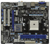
...website for specific information about the model you are using. ASRock website http://www.asrock.com If you for details. 5 ASRock A75M Motherboard English www.asrock.com/support/index.asp 1.1 Package Contents ASRock A75M Motherboard (Micro ATX Form Factor: 9.6-in x 8.5-in the ... be subject to the "User Manual" in Storage Configuration to quality and endurance. This Quick Installation Guide contains introduction of this manual will be found in the user manual presented in , 24.4 cm x 21.6 cm) ASRock A75M Quick Installation Guide ASRock A75M Support CD 2 x Serial ATA...
...website for specific information about the model you are using. ASRock website http://www.asrock.com If you for details. 5 ASRock A75M Motherboard English www.asrock.com/support/index.asp 1.1 Package Contents ASRock A75M Motherboard (Micro ATX Form Factor: 9.6-in x 8.5-in the ... be subject to the "User Manual" in Storage Configuration to quality and endurance. This Quick Installation Guide contains introduction of this manual will be found in the user manual presented in , 24.4 cm x 21.6 cm) ASRock A75M Quick Installation Guide ASRock A75M Support CD 2 x Serial ATA...
Quick Installation Guide
Page 13
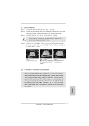
... 2.2 Installation of the pins. Step 4. You also need to spray thermal grease between the CPU and the heatsink to a 90 angle. English 13 ASRock A75M Motherboard Step 3. Unlock the socket by lifting the lever up to improve heat dissipation. DO NOT force the CPU into the socket until it is... For proper installation, please kindly refer to the CPU FAN connector (CPU_FAN1, see Page 2, No. 5). Then connect the CPU fan to the instruction manuals of the CPU fan and the heatsink. Step 2. Carefully insert the CPU into the socket to avoid bending of CPU Fan and Heatsink After you...
... 2.2 Installation of the pins. Step 4. You also need to spray thermal grease between the CPU and the heatsink to a 90 angle. English 13 ASRock A75M Motherboard Step 3. Unlock the socket by lifting the lever up to improve heat dissipation. DO NOT force the CPU into the socket until it is... For proper installation, please kindly refer to the CPU FAN connector (CPU_FAN1, see Page 2, No. 5). Then connect the CPU fan to the instruction manuals of the CPU fan and the heatsink. Step 2. Carefully insert the CPU into the socket to avoid bending of CPU Fan and Heatsink After you...

Quick Installation Guide
Page 24
... on the chassis must support HDA to function correctly. This header can be used to install your system using the power switch. 24 ASRock A75M Motherboard Please follow the instruction in the Realtek Control panel. B. English Connect the power switch, reset switch and system status indicator on ...) This header accommodates several system front panel functions. If you use AC'97 audio panel, please install it to the "FrontMic" Tab in our manual and chassis manual to connect the remote controller receiver. D. For Windows® 7 / 7 64-bit / VistaTM / VistaTM 64-bit OS: Go to the...
... on the chassis must support HDA to function correctly. This header can be used to install your system using the power switch. 24 ASRock A75M Motherboard Please follow the instruction in the Realtek Control panel. B. English Connect the power switch, reset switch and system status indicator on ...) This header accommodates several system front panel functions. If you use AC'97 audio panel, please install it to the "FrontMic" Tab in our manual and chassis manual to connect the remote controller receiver. D. For Windows® 7 / 7 64-bit / VistaTM / VistaTM 64-bit OS: Go to the...
Quick Installation Guide
Page 29
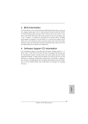
When you to display the menus. 29 ASRock A75M Motherboard English If you wish to enter BIOS Setup after POST, please restart the system by pressing + + , or pressing the reset button on the fi... program is a menu-driven program, which allows you start up the computer, please press or during the Power-On-Self-Test (POST) to the User Manual (PDF file) contained in your CDROM drive. BIOS Information The Flash Memory on the motherboard stores BIOS Setup Utility. For the detailed information about...
When you to display the menus. 29 ASRock A75M Motherboard English If you wish to enter BIOS Setup after POST, please restart the system by pressing + + , or pressing the reset button on the fi... program is a menu-driven program, which allows you start up the computer, please press or during the Power-On-Self-Test (POST) to the User Manual (PDF file) contained in your CDROM drive. BIOS Information The Flash Memory on the motherboard stores BIOS Setup Utility. For the detailed information about...

RAID Installation Guide
Page 3
... Disks", which is called data mirroring that optimizes two identical hard disk drives to configure RAID functions by following the detailed instruction of the "User Manual" in the other drive if one drive fails. After you to read and write data in a RAID 10 solution for improved performance plus resiliency...
... Disks", which is called data mirroring that optimizes two identical hard disk drives to configure RAID functions by following the detailed instruction of the "User Manual" in the other drive if one drive fails. After you to read and write data in a RAID 10 solution for improved performance plus resiliency...

RAID Installation Guide
Page 19
... reliable, on occasion a physical drive can fail. A RAID Ready logical drive disappears from the user interface when its physical drive fails. See the RAIDXpert User Manual for more information. 19 When you if there is a critical or offline logical drive. 1.11 Responding to rebuild your system, the Option ROM screen informs...
... reliable, on occasion a physical drive can fail. A RAID Ready logical drive disappears from the user interface when its physical drive fails. See the RAIDXpert User Manual for more information. 19 When you if there is a critical or offline logical drive. 1.11 Responding to rebuild your system, the Option ROM screen informs...

RAID Installation Guide
Page 23
... Host PC's IP address 127.0.0.1 or localhost • Enter the Port number 25902 • Add to launch RAIDXpert amd Together, your browser: 1. Or, log on manually with your entry looks like this: http://127.0.0.1:25902/ati or http://localhost:25902/ati 2.6 Secure Connection RAIDXpert uses a secure HTTP connection https:// 23
... Host PC's IP address 127.0.0.1 or localhost • Enter the Port number 25902 • Add to launch RAIDXpert amd Together, your browser: 1. Or, log on manually with your entry looks like this: http://127.0.0.1:25902/ati or http://localhost:25902/ati 2.6 Secure Connection RAIDXpert uses a secure HTTP connection https:// 23
