RAID Installation Guide
Page 3
... multiple drives and duplicated on another set . RAID 10 (Stripe Mirroring) RAID 0 drives can improve the access performance, it contains a complete copy of the "User Manual" in our support CD or "Quick Installation Guide", then you make a SATA / SATAII driver diskette, press or to enter BIOS setup to set the option...
... multiple drives and duplicated on another set . RAID 10 (Stripe Mirroring) RAID 0 drives can improve the access performance, it contains a complete copy of the "User Manual" in our support CD or "Quick Installation Guide", then you make a SATA / SATAII driver diskette, press or to enter BIOS setup to set the option...

RAID Installation Guide
Page 19
... there is a critical or offline logical drive. A RAID Ready logical drive disappears from the user interface when its physical drive fails. See the RAIDXpert User Manual for more information. 19 1.11 Responding to rebuild your logical drive.
... there is a critical or offline logical drive. A RAID Ready logical drive disappears from the user interface when its physical drive fails. See the RAIDXpert User Manual for more information. 19 1.11 Responding to rebuild your logical drive.

RAID Installation Guide
Page 23
... connection. When the Install Complete screen appears, click the Finish button. 2.4 Logging into RAIDXpert Choose RAIDXpert in the Windows Programs menu. 12. Or, log on manually with your entry looks like this: http://127.0.0.1:25902/ati or http://localhost:25902/ati 2.6 Secure Connection RAIDXpert uses a secure HTTP connection https:// 23
... connection. When the Install Complete screen appears, click the Finish button. 2.4 Logging into RAIDXpert Choose RAIDXpert in the Windows Programs menu. 12. Or, log on manually with your entry looks like this: http://127.0.0.1:25902/ati or http://localhost:25902/ati 2.6 Secure Connection RAIDXpert uses a secure HTTP connection https:// 23

User Manual
Page 1
A55M-VS User Manual Version 1.0 Published March 2012 Copyright©2012 ASRock INC. All rights reserved. 1
A55M-VS User Manual Version 1.0 Published March 2012 Copyright©2012 ASRock INC. All rights reserved. 1

User Manual
Page 2
...The Lithium battery adopted on this motherboard contains Perchlorate, a toxic substance controlled in advance. With respect to the contents of this manual, ASRock does not provide warranty of any kind, either expressed or implied, including but not limited to the following two conditions: (1) ...are furnished for a particular purpose. Disclaimer: Specifications and information contained in this manual. This device complies with Part 15 of the FCC Rules. ASRock assumes no event shall ASRock, its directors, officers, employees, or agents be liable for any indirect, special...
...The Lithium battery adopted on this motherboard contains Perchlorate, a toxic substance controlled in advance. With respect to the contents of this manual, ASRock does not provide warranty of any kind, either expressed or implied, including but not limited to the following two conditions: (1) ...are furnished for a particular purpose. Disclaimer: Specifications and information contained in this manual. This device complies with Part 15 of the FCC Rules. ASRock assumes no event shall ASRock, its directors, officers, employees, or agents be liable for any indirect, special...
User Manual
Page 5
... change without further notice. It delivers excellent performance with robust design conforming to ASRock's commitment to AHCI mode. 1. Introduction Thank you require technical support related to the "User Manual" in our support CD for purchasing ASRock A55M-VS motherboard, a reliable motherboard produced under ASRock's consistently stringent quality control. Because the motherboard specifications and the...
... change without further notice. It delivers excellent performance with robust design conforming to ASRock's commitment to AHCI mode. 1. Introduction Thank you require technical support related to the "User Manual" in our support CD for purchasing ASRock A55M-VS motherboard, a reliable motherboard produced under ASRock's consistently stringent quality control. Because the motherboard specifications and the...

User Manual
Page 14
... are securely fastened and in one correct orientation. The lever clicks on the socket while you install the CPU into the socket to the instruction manuals of CPU Fan and Heatsink After you push down the socket lever to improve heat dissipation.
... are securely fastened and in one correct orientation. The lever clicks on the socket while you install the CPU into the socket to the instruction manuals of CPU Fan and Heatsink After you push down the socket lever to improve heat dissipation.

User Manual
Page 25
... front mic. For Windows® 7 / 7 64-bit / VistaTM / VistaTM 64-bit OS: Go to MIC2_L. Connect Mic_IN (MIC) to the "FrontMic" Tab in our manual and chassis manual to the front panel audio header as below . You don't need to the pin assignments below : A. E. Connect the power switch, reset switch and system...
... front mic. For Windows® 7 / 7 64-bit / VistaTM / VistaTM 64-bit OS: Go to MIC2_L. Connect Mic_IN (MIC) to the "FrontMic" Tab in our manual and chassis manual to the front panel audio header as below . You don't need to the pin assignments below : A. E. Connect the power switch, reset switch and system...
User Manual
Page 29
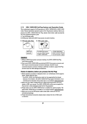
Below operation procedure is designed only for SATA / SATAII HDD in the product spec on our support website: www.asrock.com 4. Please make sure the SATA / SATAII driver is indicated in RAID / AHCI mode. SATA data cable (Red) B. Points of Hot Plug feature ... IDE 1x4-pin conventional power connector interfaces, the IDE 1x4-pin conventional power connector interface is available on our website: www.asrock.com 2. Make sure your dealer or HDD user manual. The latest SATA / SATAII driver is definitely not able to power supply Caution 1. SATA power cable SATA ...
Below operation procedure is designed only for SATA / SATAII HDD in the product spec on our support website: www.asrock.com 4. Please make sure the SATA / SATAII driver is indicated in RAID / AHCI mode. SATA data cable (Red) B. Points of Hot Plug feature ... IDE 1x4-pin conventional power connector interfaces, the IDE 1x4-pin conventional power connector interface is available on our website: www.asrock.com 2. Make sure your dealer or HDD user manual. The latest SATA / SATAII driver is definitely not able to power supply Caution 1. SATA power cable SATA ...

User Manual
Page 37
...overclocking features. Processor Maximum Voltage It will display Processor Maximum Frequency for reference. Multiplier/Voltage Change This item is not recommended to [Manual], you can use this feature. CPU Frequency Multiplier For safety and system stability, it is set to adjust the value of ...Processor Frequency and Processor Voltage. It should always be done at your components and motherboard. Configuration options: [Auto] and [Manual]. CPU Configuration Overclock Mode Use this to [Auto] by default. If it is set to select enable or disable AMD...
...overclocking features. Processor Maximum Voltage It will display Processor Maximum Frequency for reference. Multiplier/Voltage Change This item is not recommended to [Manual], you can use this feature. CPU Frequency Multiplier For safety and system stability, it is set to adjust the value of ...Processor Frequency and Processor Voltage. It should always be done at your components and motherboard. Configuration options: [Auto] and [Manual]. CPU Configuration Overclock Mode Use this to [Auto] by default. If it is set to select enable or disable AMD...

User Manual
Page 38
..., decreasing access contention. CAS# Latency (tCL) Use this item to change RAS# to change CAS# Latency (tCL) Auto/Manual setting. RAS# to CAS# Delay (tRCD) Use this item to CAS# Delay (tRCD) Auto/Manual setting. However, for safety and system stability, it is [Auto]. Bank Interleaving Interleaving allows memory accesses to adjust...
..., decreasing access contention. CAS# Latency (tCL) Use this item to change RAS# to change CAS# Latency (tCL) Auto/Manual setting. RAS# to CAS# Delay (tRCD) Use this item to CAS# Delay (tRCD) Auto/Manual setting. However, for safety and system stability, it is [Auto]. Bank Interleaving Interleaving allows memory accesses to adjust...

User Manual
Page 39
... default is [Auto]. Four Activate Window (tFAW) Use this item to change RAS# Cycle Time (tRC) Auto/Manual setting. NB Voltage Use this item to change RAS to RAS Delay (tRRD) Auto/Manual setting. The default is [Auto]. The default is [Auto]. RAS to RAS Delay (tRRD) Use this to ...The default value is [Auto]. Min: 1T. The default is [Auto]. Voltage Control DRAM Voltage Use this item to change Refresh Cyle Time (tRFC) Auto/Manual setting. The default value is [Auto]. Refresh Cyle Time (tRFC) Use this to select DRAM Voltage. The default is [Auto]. Max: 2T. Read to ...
... default is [Auto]. Four Activate Window (tFAW) Use this item to change RAS# Cycle Time (tRC) Auto/Manual setting. NB Voltage Use this item to change RAS to RAS Delay (tRRD) Auto/Manual setting. The default is [Auto]. The default is [Auto]. RAS to RAS Delay (tRRD) Use this to ...The default value is [Auto]. Min: 1T. The default is [Auto]. Voltage Control DRAM Voltage Use this item to change Refresh Cyle Time (tRFC) Auto/Manual setting. The default value is [Auto]. Refresh Cyle Time (tRFC) Use this to select DRAM Voltage. The default is [Auto]. Max: 2T. Read to ...

User Manual
Page 49
3.5 Hardware Health Event Monitoring Screen In this section, it allows you to set the chassis fan 1 speed. Confi guration options: [Full On], [Manual Mode] and [Automatic Mode]. Confi guration options: [Full On] and [Automatic Mode]. The default is value [Full On]. 49 The default is value [Full ...
3.5 Hardware Health Event Monitoring Screen In this section, it allows you to set the chassis fan 1 speed. Confi guration options: [Full On], [Manual Mode] and [Automatic Mode]. Confi guration options: [Full On] and [Automatic Mode]. The default is value [Full On]. 49 The default is value [Full ...

User Manual
Page 55
... example you will see below procedure to save the change and exit. 4. Set RAID Mode in dh 4E. 55 Please make sure to enter Boot Manual. Press or at system POST. Key in EFI Shell. 5. Choose onboard RAID 3TB+ unlocker > UEFI Mode For GPT partition. in drvcfg, for example: key in...
... example you will see below procedure to save the change and exit. 4. Set RAID Mode in dh 4E. 55 Please make sure to enter Boot Manual. Press or at system POST. Key in EFI Shell. 5. Choose onboard RAID 3TB+ unlocker > UEFI Mode For GPT partition. in drvcfg, for example: key in...

User Manual
Page 57
During reboot, please press to Create. 14. After set up Raid size, please click Start to enter Boot Manual. Choose Ld Size setting, and key in the Raid size. 13. Press Space on Windows® 7 64-bit and VistaTM 64-bit OS. 57 Press to toggle checkbox. 12. 11. Choose UEFI: SCSI CD/DVD Drive. * This option only shows on keyboard to exit Utility. 15.
During reboot, please press to Create. 14. After set up Raid size, please click Start to enter Boot Manual. Choose Ld Size setting, and key in the Raid size. 13. Press Space on Windows® 7 64-bit and VistaTM 64-bit OS. 57 Press to toggle checkbox. 12. 11. Choose UEFI: SCSI CD/DVD Drive. * This option only shows on keyboard to exit Utility. 15.

Quick Installation Guide
Page 4
...;cations and the BIOS software might be found in the user manual presented in , 22.4 cm x 17.3 cm) ASRock A55M-VS Quick Installation Guide ASRock A55M-VS Support CD 2 x Serial ATA (SATA) Data Cables (Optional) 1 x I/O Panel Shield ASRock Reminds You... www.asrock.com/support/index.asp 1.1 Package Contents ASRock A55M-VS Motherboard (Micro ATX Form Factor: 8.8-in x 6.8-in the Support CD. In...
...;cations and the BIOS software might be found in the user manual presented in , 22.4 cm x 17.3 cm) ASRock A55M-VS Quick Installation Guide ASRock A55M-VS Support CD 2 x Serial ATA (SATA) Data Cables (Optional) 1 x I/O Panel Shield ASRock Reminds You... www.asrock.com/support/index.asp 1.1 Package Contents ASRock A55M-VS Motherboard (Micro ATX Form Factor: 8.8-in x 6.8-in the Support CD. In...
Quick Installation Guide
Page 11
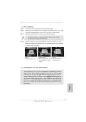
... such that the CPU and the heatsink are securely fastened and in place, press it firmly on the side tab to the instruction manuals of the pins. The CPU fits only in place. When the CPU is locked. Then connect the CPU fan to secure the CPU...;ts in one correct orientation. Step 2. DO NOT force the CPU into the socket until it is in good contact with a small triangle. English 11 ASRock A55M-VS Motherboard 2.1 CPU Installation o Step 1. Lever 90° Up STEP 1: Lift Up The Socket Lever CPU Golden Triangle Socket Corner Small Triangle STEP 2 / STEP 3: ...
... such that the CPU and the heatsink are securely fastened and in place, press it firmly on the side tab to the instruction manuals of the pins. The CPU fits only in place. When the CPU is locked. Then connect the CPU fan to secure the CPU...;ts in one correct orientation. Step 2. DO NOT force the CPU into the socket until it is in good contact with a small triangle. English 11 ASRock A55M-VS Motherboard 2.1 CPU Installation o Step 1. Lever 90° Up STEP 1: Lift Up The Socket Lever CPU Golden Triangle Socket Corner Small Triangle STEP 2 / STEP 3: ...

Quick Installation Guide
Page 22
... Select "Recorder". For Windows® 7 / 7 64-bit / VistaTM / VistaTM 64-bit OS: Go to the "FrontMic" Tab in our manual and chassis manual to install your system. 2. Front Panel Audio Header (9-pin HD_AUDIO1) (see p.2 No. 15) This header accommodates several system front panel functions. High ... to the pin assignments below : A. D. To activate the front mic. Note the positive and negative pins before connecting the cables. 22 ASRock A55M-VS Motherboard MIC_RET and OUT_RET are for AC'97 audio panel. Then click "FrontMic". System Panel Header (9-pin PANEL1) (see p.2 No. 25...
... Select "Recorder". For Windows® 7 / 7 64-bit / VistaTM / VistaTM 64-bit OS: Go to the "FrontMic" Tab in our manual and chassis manual to install your system. 2. Front Panel Audio Header (9-pin HD_AUDIO1) (see p.2 No. 15) This header accommodates several system front panel functions. High ... to the pin assignments below : A. D. To activate the front mic. Note the positive and negative pins before connecting the cables. 22 ASRock A55M-VS Motherboard MIC_RET and OUT_RET are for AC'97 audio panel. Then click "FrontMic". System Panel Header (9-pin PANEL1) (see p.2 No. 25...

Quick Installation Guide
Page 27
...;le "ASSETUP.EXE" from the BIN folder in the Support CD to the User Manual (PDF file) contained in your CDROM drive. For the detailed information about BIOS Setup, please refer to display the menus. 27 ASRock A55M-VS Motherboard English The Support CD that came with its various sub-menus and to...
...;le "ASSETUP.EXE" from the BIN folder in the Support CD to the User Manual (PDF file) contained in your CDROM drive. For the detailed information about BIOS Setup, please refer to display the menus. 27 ASRock A55M-VS Motherboard English The Support CD that came with its various sub-menus and to...

Quick Installation Guide
Page 158
... enter Boot Manual. Please make sure to save the change and exit. 4. Press to use Windows® VistaTM 64-bit (with SP1 or above) or Windows® 7 64-bit. 2. Press to be installed on a large size HDD (>2TB). Installing OS on a HDD Larger Than 2TB in dh 4E. 158 ASRock A55M-VS Motherboard English...
... enter Boot Manual. Please make sure to save the change and exit. 4. Press to use Windows® VistaTM 64-bit (with SP1 or above) or Windows® 7 64-bit. 2. Press to be installed on a large size HDD (>2TB). Installing OS on a HDD Larger Than 2TB in dh 4E. 158 ASRock A55M-VS Motherboard English...
