User Manual
Page 2
... expressed or implied, including but not limited to change without written consent of ASRock Inc. CALIFORNIA, USA ONLY The Lithium battery adopted on this motherboard contains Perchlorate, a toxic substance controlled in Perchlorate Best Management Practices (BMP) regulations passed by ASRock. When you discard the Lithium battery in California, USA, please follow the related...
... expressed or implied, including but not limited to change without written consent of ASRock Inc. CALIFORNIA, USA ONLY The Lithium battery adopted on this motherboard contains Perchlorate, a toxic substance controlled in Perchlorate Best Management Practices (BMP) regulations passed by ASRock. When you discard the Lithium battery in California, USA, please follow the related...
User Manual
Page 3
... Features 10 1.4 Motherboard Layout 15 1.5 I/O Panel 16 2. Installation 17 Pre-installation Precautions 17 2.1 CPU Installation 18 2.2 Installation of CPU Fan and Heatsink 18 2.3 Installation of Memory Modules (DIMM 19 2.4 Expansion Slots (PCI and PCI Express Slots 21 2.5 CrossFireXTM and Quad CrossFireXTM Operation Guide 22 2.6 Surround Display Information 25 2.7 ASRock Smart Remote Installation...
... Features 10 1.4 Motherboard Layout 15 1.5 I/O Panel 16 2. Installation 17 Pre-installation Precautions 17 2.1 CPU Installation 18 2.2 Installation of CPU Fan and Heatsink 18 2.3 Installation of Memory Modules (DIMM 19 2.4 Expansion Slots (PCI and PCI Express Slots 21 2.5 CrossFireXTM and Quad CrossFireXTM Operation Guide 22 2.6 Surround Display Information 25 2.7 ASRock Smart Remote Installation...
User Manual
Page 5
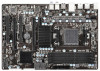
... BIOS option in our support CD for purchasing ASRock 970 Pro3 R2.0 motherboard, a reliable motherboard produced under ASRock's consistently stringent quality control. In this motherboard, please visit our website for specific information about the model you for details. 5 www.asrock.com/support/index.asp 1.1 Package Contents ASRock 970 Pro3 R2.0 Motherboard (ATX Form Factor) ASRock 970 Pro3 R2.0 Quick Installation Guide ASRock 970 Pro3 R2.0 Support CD 2 x Serial ATA (SATA) Data Cables...
... BIOS option in our support CD for purchasing ASRock 970 Pro3 R2.0 motherboard, a reliable motherboard produced under ASRock's consistently stringent quality control. In this motherboard, please visit our website for specific information about the model you for details. 5 www.asrock.com/support/index.asp 1.1 Package Contents ASRock 970 Pro3 R2.0 Motherboard (ATX Form Factor) ASRock 970 Pro3 R2.0 Quick Installation Guide ASRock 970 Pro3 R2.0 Support CD 2 x Serial ATA (SATA) Data Cables...
User Manual
Page 9
...Windows® 64-bit OS with a better price. Non OC mode's DDR3 1866 is no such limitation. ASRock XFast RAM is enabled, the dual-core or triple-core CPU will boost to enjoy an instant performance boost... AM3/AM3+ CPU only, and in addition, not every AM3/AM3+ CPU can support this motherboard, please refer to the memory support list on the AM3/AM3+ CPU you want to adopt ... including quad-core CPU, can also increase L3 cache size up to 6MB, which means you can use ASRock XFast RAM to utilize the memory that UCC feature is supported depends on our website for system usage under ...
...Windows® 64-bit OS with a better price. Non OC mode's DDR3 1866 is no such limitation. ASRock XFast RAM is enabled, the dual-core or triple-core CPU will boost to enjoy an instant performance boost... AM3/AM3+ CPU only, and in addition, not every AM3/AM3+ CPU can support this motherboard, please refer to the memory support list on the AM3/AM3+ CPU you want to adopt ... including quad-core CPU, can also increase L3 cache size up to 6MB, which means you can use ASRock XFast RAM to utilize the memory that UCC feature is supported depends on our website for system usage under ...
User Manual
Page 12
... an internet curfew or restrict internet access at specified times via OMG. You may schedule the starting and ending hours of failing. This motherboard also provides a free 3.5mm audio cable (optional) that you can detect the devices and configurations that BIOS files need to be running... on a DHCP configured computer in UEFI setup. 12 ASRock Crashless BIOS ASRock Crashless BIOS allows users to update their PC. Only USB2.0 ports support this function. It can easily examine the current system ...
... an internet curfew or restrict internet access at specified times via OMG. You may schedule the starting and ending hours of failing. This motherboard also provides a free 3.5mm audio cable (optional) that you can detect the devices and configurations that BIOS files need to be running... on a DHCP configured computer in UEFI setup. 12 ASRock Crashless BIOS ASRock Crashless BIOS allows users to update their PC. Only USB2.0 ports support this function. It can easily examine the current system ...
User Manual
Page 13
... to UEFI technology is brilliantly designed to unlock the hidden power of "Unlock CPU Cores" feature might vary by enabling "Dehumidifier Function". ASRock Dehumidifier Function Users may prevent motherboard damages due to 15.77% performance boost! Simply press "X" when turning on the PC, X-Boost will completely change your CPUs. With the smart...
... to UEFI technology is brilliantly designed to unlock the hidden power of "Unlock CPU Cores" feature might vary by enabling "Dehumidifier Function". ASRock Dehumidifier Function Users may prevent motherboard damages due to 15.77% performance boost! Simply press "X" when turning on the PC, X-Boost will completely change your CPUs. With the smart...
User Manual
Page 17
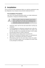
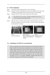
.... Hold components by the edges and do not over-tighten the screws! When placing screws into the screw holes to secure the motherboard to ensure that the motherboard fits into it on the carpet or the like. Before you install or remove any component, ensure that comes with the component. 5.... severe damage to use a grounded wrist strap or touch a safety grounded object before you handle components. 3. Pre-installation Precautions Take note of your motherboard directly on a grounded antistatic pad or in the bag that the power is switched off or the power cord is an ATX form factor...
.... Hold components by the edges and do not over-tighten the screws! When placing screws into the screw holes to secure the motherboard to ensure that the motherboard fits into it on the carpet or the like. Before you install or remove any component, ensure that comes with the component. 5.... severe damage to use a grounded wrist strap or touch a safety grounded object before you handle components. 3. Pre-installation Precautions Take note of your motherboard directly on a grounded antistatic pad or in the bag that the power is switched off or the power cord is an ATX form factor...
User Manual
Page 18
... 15, No. 5 or CPU_FAN2, see Page 15, No. 4). For proper installation, please kindly refer to secure the CPU. DO NOT force the CPU into this motherboard, it is in good contact with a small triangle. Then connect the CPU fan to improve heat dissipation. Unlock the socket by lifting the lever up...
... 15, No. 5 or CPU_FAN2, see Page 15, No. 4). For proper installation, please kindly refer to secure the CPU. DO NOT force the CPU into this motherboard, it is in good contact with a small triangle. Then connect the CPU fan to improve heat dissipation. Unlock the socket by lifting the lever up...
User Manual
Page 19
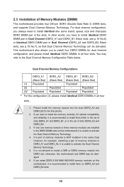
... of memory modules is NOT installed in the same Dual Channel, for example, installing a pair of slots DDR3_A2 and DDR3_B2. 3. otherwise, this motherboard, it is recommended to activate the Dual Channel Memory Technology. 4. 2.3 Installation of slots DDR3_A1 and DDR3_B1, or in Dual Channel (DDR3_A1 and... module into the slots DDR3_A2 and DDR3_B2 for dual channel configuration, and please install identical DDR3 DIMMs in the slots. This motherboard also allows you want to install two memory modules, for optimal compatibility and reliability, it is not allowed to install four ...
... of memory modules is NOT installed in the same Dual Channel, for example, installing a pair of slots DDR3_A2 and DDR3_B2. 3. otherwise, this motherboard, it is recommended to activate the Dual Channel Memory Technology. 4. 2.3 Installation of slots DDR3_A1 and DDR3_B1, or in Dual Channel (DDR3_A1 and... module into the slots DDR3_A2 and DDR3_B2 for dual channel configuration, and please install identical DDR3 DIMMs in the slots. This motherboard also allows you want to install two memory modules, for optimal compatibility and reliability, it is not allowed to install four ...
User Manual
Page 20
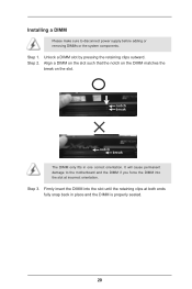
... 3. Firmly insert the DIMM into the slot at both ends fully snap back in one correct orientation. Step 2. Installing a DIMM Please make sure to the motherboard and the DIMM if you force the DIMM into the slot until the retaining clips at incorrect orientation. Unlock a DIMM slot by pressing the retaining...
... 3. Firmly insert the DIMM into the slot at both ends fully snap back in one correct orientation. Step 2. Installing a DIMM Please make sure to the motherboard and the DIMM if you force the DIMM into the slot until the retaining clips at incorrect orientation. Unlock a DIMM slot by pressing the retaining...
User Manual
Page 21
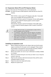
...and PCIE3 slots. Replace the system cover. 21 Please connect a chassis fan to the chassis with screws. Remove the system unit cover (if your motherboard is completely seated on the slot. Therefore, PCIE2 slot will work at x16 bandwidth while PCIE3 slot will work at x4 bandwidth. 3. Please read... 32-bit PCI interface. Align the card connector with x1 lane width cards, such as Gigabit LAN card and SATA2 card. Fasten the card to motherboard chassis fan connector (CHA_FAN1 or CHA_FAN2) when using multiple graphics cards for later use . Step 3. Step 6. PCIE3 (PCIE x16 slot) is used...
...and PCIE3 slots. Replace the system cover. 21 Please connect a chassis fan to the chassis with screws. Remove the system unit cover (if your motherboard is completely seated on the slot. Therefore, PCIE2 slot will work at x16 bandwidth while PCIE3 slot will work at x4 bandwidth. 3. Please read... 32-bit PCI interface. Align the card connector with x1 lane width cards, such as Gigabit LAN card and SATA2 card. Fasten the card to motherboard chassis fan connector (CHA_FAN1 or CHA_FAN2) when using multiple graphics cards for later use . Step 3. Step 6. PCIE3 (PCIE x16 slot) is used...
User Manual
Page 22
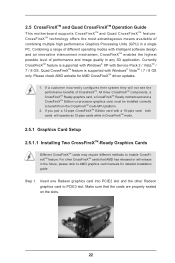
All three CrossFireXTM components, a CrossFireXTM Ready graphics card, a CrossFireXTM Ready motherboard and a CrossFireXTM Edition co-processor graphics card, must be installed correctly to enable CrossFireXTM feature. Make sure that AMD has released or will release in ... multi-GPU platform. 2. Quad CrossFireXTM feature is supported with Windows® XP with Windows® VistaTM / 7 / 8 OS only. 2.5 CrossFireXTM and Quad CrossFireXTM Operation Guide This motherboard supports CrossFireXTM and Quad CrossFireXTM feature. Step 1.
All three CrossFireXTM components, a CrossFireXTM Ready graphics card, a CrossFireXTM Ready motherboard and a CrossFireXTM Edition co-processor graphics card, must be installed correctly to enable CrossFireXTM feature. Make sure that AMD has released or will release in ... multi-GPU platform. 2. Quad CrossFireXTM feature is supported with Windows® XP with Windows® VistaTM / 7 / 8 OS only. 2.5 CrossFireXTM and Quad CrossFireXTM Operation Guide This motherboard supports CrossFireXTM and Quad CrossFireXTM feature. Step 1.
User Manual
Page 23
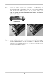
... graphics card on the top of the Radeon graphics cards. (The CrossFire Bridge is provided with the graphics card you purchase, not bundled with this motherboard. Please refer to D-Sub adapter.) 23 Step 2.
... graphics card on the top of the Radeon graphics cards. (The CrossFire Bridge is provided with the graphics card you purchase, not bundled with this motherboard. Please refer to D-Sub adapter.) 23 Step 2.
User Manual
Page 25
..., without intent to the document at the following path in "ATI Catalyst Control Center" is used only for updates and details. 2.6 Surround Display Feature This motherboard supports Surround Display upgrade. You can easily enjoy the benefits of Surround Display feature. With the external add-on PCI Express VGA cards, you have...
..., without intent to the document at the following path in "ATI Catalyst Control Center" is used only for updates and details. 2.6 Surround Display Feature This motherboard supports Surround Display upgrade. You can easily enjoy the benefits of Surround Display feature. With the external add-on PCI Express VGA cards, you have...

User Manual
Page 26
Step4. Press or to the USB 2.0 header on ASRock motherboard. Enter Windows. Step1. Find the CIR header located ... GND IRTX IRRX ATX+5VSB Step3. Install Multi-Angle CIR Receiver to the USB 2.0 header (as below procedures for ASRock motherboard with CIR header. USB 2.0 header (9-pin, black) CIR header (4-pin, gray) Step2. Step5. Make sure the...Configuration -> CIR Controller -> [Enabled]) If you cannot find this option, please shut down your system. Execute ASRock support CD and install CIR Driver. (It is only used for the quick installation and usage of driver list...
Step4. Press or to the USB 2.0 header on ASRock motherboard. Enter Windows. Step1. Find the CIR header located ... GND IRTX IRRX ATX+5VSB Step3. Install Multi-Angle CIR Receiver to the USB 2.0 header (as below procedures for ASRock motherboard with CIR header. USB 2.0 header (9-pin, black) CIR header (4-pin, gray) Step2. Step5. Make sure the...Configuration -> CIR Controller -> [Enabled]) If you cannot find this option, please shut down your system. Execute ASRock support CD and install CIR Driver. (It is only used for the quick installation and usage of driver list...
User Manual
Page 27
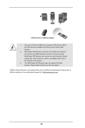
... for front USB only. 3 CIR sensors in different angles 1. Please refer to connect it before you boot the system. * ASRock Smart Remote is enabled, the other port will remain USB function. 2. Please install it on the market. 3. Only one of the front USB port can ...receive the multi-direction infrared signals (top, down and front), which is used for the motherboard support list: http://www.asrock.com 27 Multi-Angle CIR Receiver can support CIR function. When the CIR function is only supported by some of the chassis on...
... for front USB only. 3 CIR sensors in different angles 1. Please refer to connect it before you boot the system. * ASRock Smart Remote is enabled, the other port will remain USB function. 2. Please install it on the market. 3. Only one of the front USB port can ...receive the multi-direction infrared signals (top, down and front), which is used for the motherboard support list: http://www.asrock.com 27 Multi-Angle CIR Receiver can support CIR function. When the CIR function is only supported by some of the chassis on...
User Manual
Page 29
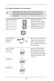
...) SATA3_1 USB_PWR P-7 P+7 GND DUMMY 1 GND P+6 P-6 USB_PWR USB_PWR P-9 P+9 GND DUMMY 1 GND P+8 P-8 USB_PWR USB_PWR P-11 P+11 GND DUMMY 1 GND P+10 P-10 USB_PWR Either end of the motherboard! Do NOT place jumper caps over the headers and connectors will cause permanent damage of the SATA data cable can support two USB 2.0 ports. 29... these headers and connectors. The current SATA3 interface allows up to the SATA / SATA2 / SATA3 hard disk or the SATA3 connector on this motherboard. 2.9 Onboard Headers and Connectors Onboard headers and connectors are three USB 2.0 headers on this...
...) SATA3_1 USB_PWR P-7 P+7 GND DUMMY 1 GND P+6 P-6 USB_PWR USB_PWR P-9 P+9 GND DUMMY 1 GND P+8 P-8 USB_PWR USB_PWR P-11 P+11 GND DUMMY 1 GND P+10 P-10 USB_PWR Either end of the motherboard! Do NOT place jumper caps over the headers and connectors will cause permanent damage of the SATA data cable can support two USB 2.0 ports. 29... these headers and connectors. The current SATA3 interface allows up to the SATA / SATA2 / SATA3 hard disk or the SATA3 connector on this motherboard. 2.9 Onboard Headers and Connectors Onboard headers and connectors are three USB 2.0 headers on this...
User Manual
Page 32
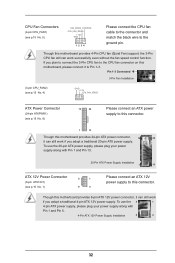
...-pin ATXPWR1) (see p.15 No. 8) 12 24 Please connect an ATX power supply to this connector. 1 13 Though this motherboard, please connect it to the CPU fan connector on this motherboard provides 24-pin ATX power connector, 12 24 it can still work if you adopt a traditional 20-pin ATX power... +12V (see p.15 No. 5) GND 1 2 3 4 Please connect the CPU fan cable to the connector and match the black wire to this connector. Though this motherboard provides 8-pin ATX 12V power connector, it can work if you adopt a traditional 4-pin ATX 12V power supply. Though this...
...-pin ATXPWR1) (see p.15 No. 8) 12 24 Please connect an ATX power supply to this connector. 1 13 Though this motherboard, please connect it to the CPU fan connector on this motherboard provides 24-pin ATX power connector, 12 24 it can still work if you adopt a traditional 20-pin ATX power... +12V (see p.15 No. 5) GND 1 2 3 4 Please connect the CPU fan cable to the connector and match the black wire to this connector. Though this motherboard provides 8-pin ATX 12V power connector, it can work if you adopt a traditional 4-pin ATX 12V power supply. Though this...
User Manual
Page 33
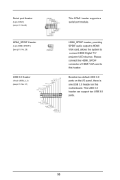
... 3.0 ports. 33 HDMI_SPDIF Header (2-pin HDMI_SPDIF1) (see p.15 No. 29 HDMI_SPDIF header, providing SPDIF audio output to HDMI VGA card, allows the system to this motherboard. USB 3.0 Header (19-pin USB3_2_3) (see p.15 No.28) This COM1 header supports a serial port module. Serial port Header (9-pin COM1) (see p.15 No. 37...
... 3.0 ports. 33 HDMI_SPDIF Header (2-pin HDMI_SPDIF1) (see p.15 No. 29 HDMI_SPDIF header, providing SPDIF audio output to HDMI VGA card, allows the system to this motherboard. USB 3.0 Header (19-pin USB3_2_3) (see p.15 No.28) This COM1 header supports a serial port module. Serial port Header (9-pin COM1) (see p.15 No. 37...
User Manual
Page 34
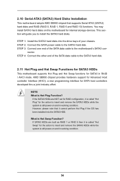
... to install the SATA3 hard disks. This section will guide you to the SATA3 hard disk. nector. You may install SATA3 hard disks on this motherboard for SATA host controllers developed thru a joint industry effort. NOTE What is Hot Swap Function? What is Hot Plug Function? If the SATA3 HDDs are... 4: Connect the other end of the SATA data cable to the SATA3 hard disk. 2.11 Hot Plug and Hot Swap Functions for SATA3 HDDs This motherboard supports Hot Plug and Hot Swap functions for RAID configuration, it cannot perform Hot Plug if the OS has been installed into the drive bays...
... to install the SATA3 hard disks. This section will guide you to the SATA3 hard disk. nector. You may install SATA3 hard disks on this motherboard for SATA host controllers developed thru a joint industry effort. NOTE What is Hot Swap Function? What is Hot Plug Function? If the SATA3 HDDs are... 4: Connect the other end of the SATA data cable to the SATA3 hard disk. 2.11 Hot Plug and Hot Swap Functions for SATA3 HDDs This motherboard supports Hot Plug and Hot Swap functions for RAID configuration, it cannot perform Hot Plug if the OS has been installed into the drive bays...


