RAID Installation Guide
Page 3
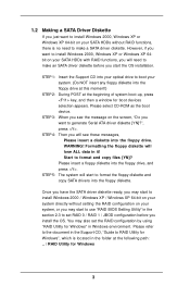
...to format and copy files [YN]? Please insert a floppy diskette into the floppy drive. STEP 1: Insert the Support CD into your optical drive to boot your system. (Do NOT insert any floppy diskette into the floppy diskette. STEP 4: Then you will lose ALL data in the section 2.3 to set...you may also set RAID 0 / RAID 1 / JBOD configuration before you start the OS installation. You may start to use "RAID BIOS Setting Utility" in it! Please select CD-ROM as the boot device. Start to make a SATA driver diskette. Once you have the SATA driver diskette ready, you install the OS.
...to format and copy files [YN]? Please insert a floppy diskette into the floppy drive. STEP 1: Insert the Support CD into your optical drive to boot your system. (Do NOT insert any floppy diskette into the floppy diskette. STEP 4: Then you will lose ALL data in the section 2.3 to set...you may also set RAID 0 / RAID 1 / JBOD configuration before you start the OS installation. You may start to use "RAID BIOS Setting Utility" in it! Please select CD-ROM as the boot device. Start to make a SATA driver diskette. Once you have the SATA driver diskette ready, you install the OS.
RAID Installation Guide
Page 8
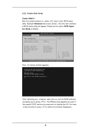
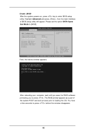
...the system POST and boot process prior to press . Please set the option SATA Opera tion Mode to press before the window disappears. 8 NVIDIA RAID IDE ROM BIOS 4.81 Copyright (C) 2004 NVIDIA Corp. You have a few seconds to [RAID]. Advanced BIOS SETUP UTILITY IDE ...Configuration OnBoard IDE Controller OnBoard SATA Controller SATA Operation Mode Primary IDE Master Primary IDE Slave Secondary IDE Master Secondary IDE Slave SATA1 SATA2 [Both] [Enabled] [RAID] [Hard Disk] [Not Detected] [ATAPI...
...the system POST and boot process prior to press . Please set the option SATA Opera tion Mode to press before the window disappears. 8 NVIDIA RAID IDE ROM BIOS 4.81 Copyright (C) 2004 NVIDIA Corp. You have a few seconds to [RAID]. Advanced BIOS SETUP UTILITY IDE ...Configuration OnBoard IDE Controller OnBoard SATA Controller SATA Operation Mode Primary IDE Master Primary IDE Slave Secondary IDE Master Secondary IDE Slave SATA1 SATA2 [Both] [Enabled] [RAID] [Hard Disk] [Not Detected] [ATAPI...
RAID Installation Guide
Page 12
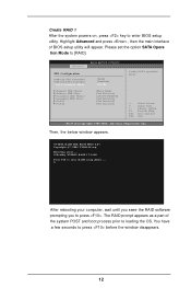
...SATA2 [Both] [Enabled] [RAID] [Hard Disk] [Not Detected] [ATAPI CDROM] [Not Detected] [Not Detected] [Not Detected] Config SATA operation mode. +F1 F10 ESC Select Screen Select Item Change Option General Help Save and Exit Exit v02.53 (C) Copyright 1985-2004. The RAID prompt appears as a part of BIOS...press , then the main interface of the system POST and boot process prior to [RAID]. American Megatrends, Inc. Detecting array . . . 0 Healthy NVIDIA RAID 1 74.54G Press F10 to press . NVIDIA RAID IDE ROM BIOS 4.81 Copyright (C) 2004 NVIDIA Corp. After rebooting your ...
...SATA2 [Both] [Enabled] [RAID] [Hard Disk] [Not Detected] [ATAPI CDROM] [Not Detected] [Not Detected] [Not Detected] Config SATA operation mode. +F1 F10 ESC Select Screen Select Item Change Option General Help Save and Exit Exit v02.53 (C) Copyright 1985-2004. The RAID prompt appears as a part of BIOS...press , then the main interface of the system POST and boot process prior to [RAID]. American Megatrends, Inc. Detecting array . . . 0 Healthy NVIDIA RAID 1 74.54G Press F10 to press . NVIDIA RAID IDE ROM BIOS 4.81 Copyright (C) 2004 NVIDIA Corp. After rebooting your ...
RAID Installation Guide
Page 15
Please set the option SATA Opera tion Mode to press . Advanced BIOS SETUP UTILITY IDE Configuration OnBoard IDE Controller OnBoard SATA Controller SATA Operation Mode Primary IDE Master Primary IDE Slave Secondary IDE Master Secondary IDE Slave SATA1 SATA2 [Both] [Enabled] [RAID] [Hard Disk] [Not Detected] [...(C) Copyright 1985-2004. Then, the below window appears. Highlight Advanced and press , then the main interface of the system POST and boot process prior to enter RAID setup utility . . . After rebooting your computer, wait until you seee the RAID software prompting you to...
Please set the option SATA Opera tion Mode to press . Advanced BIOS SETUP UTILITY IDE Configuration OnBoard IDE Controller OnBoard SATA Controller SATA Operation Mode Primary IDE Master Primary IDE Slave Secondary IDE Master Secondary IDE Slave SATA1 SATA2 [Both] [Enabled] [RAID] [Hard Disk] [Not Detected] [...(C) Copyright 1985-2004. Then, the below window appears. Highlight Advanced and press , then the main interface of the system POST and boot process prior to enter RAID setup utility . . . After rebooting your computer, wait until you seee the RAID software prompting you to...
RAID Utility for Windows Guide
Page 2
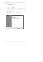
Go to the system BIOS and make sure that the drives that you want to Windows and launch the NVRAIDMAN application. 3. Boot to use are RAID enabled. 2. Create Array and the following . 1. 2. Creating RAID Arrays Creating RAID 0 (Striping) NVRAIDMAN can be used to create a striped array from one disk up to the maximum supported number of disks in the system. To create a twodisk Striped Array do the following screen will appear. 2
Go to the system BIOS and make sure that the drives that you want to Windows and launch the NVRAIDMAN application. 3. Boot to use are RAID enabled. 2. Create Array and the following . 1. 2. Creating RAID Arrays Creating RAID 0 (Striping) NVRAIDMAN can be used to create a striped array from one disk up to the maximum supported number of disks in the system. To create a twodisk Striped Array do the following screen will appear. 2
RAID Utility for Windows Guide
Page 6
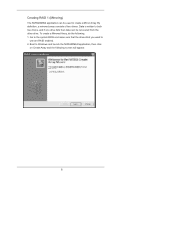
To create a Mirrored Array, do the following screen will appear. 6 Data is written to both two drives, and if one drive fails then data can be recovered from the other drive. Creating RAID 1 (Mirroring) The NVRAIDMAN application can be used to create a Mirror Array. Go to the system BIOS and make sure that the drives that you want to Windows and launch the NVRAIDMAN application, then click on Create Array and the following . 1. Boot to use are RAID enabled. 2. By definition, a mirrored array consists of two drives.
To create a Mirrored Array, do the following screen will appear. 6 Data is written to both two drives, and if one drive fails then data can be recovered from the other drive. Creating RAID 1 (Mirroring) The NVRAIDMAN application can be used to create a Mirror Array. Go to the system BIOS and make sure that the drives that you want to Windows and launch the NVRAIDMAN application, then click on Create Array and the following . 1. Boot to use are RAID enabled. 2. By definition, a mirrored array consists of two drives.

RAID Utility for Windows Guide
Page 10
Click Next and the following : 1. Go to the system BIOS and make sure that the drives that you want to Windows and launch the NVRAIDMAN application, then click on Create Array and the following screen will appear. 10 Boot to use are RAID enabled. 2. To create a Spanning Array do the following screen will appear. 3. Creating JBOD (Spanning) NVRAIDMAN can be used to create a Spanning Array which requires at least one disk to start such an array.
Click Next and the following : 1. Go to the system BIOS and make sure that the drives that you want to Windows and launch the NVRAIDMAN application, then click on Create Array and the following screen will appear. 10 Boot to use are RAID enabled. 2. To create a Spanning Array do the following screen will appear. 3. Creating JBOD (Spanning) NVRAIDMAN can be used to create a Spanning Array which requires at least one disk to start such an array.
User Manual
Page 3
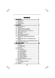
... 9 1.4 ASRock 8CH I/O 10 2 . BIOS SETUP UTILITY 24 3.1 Introduction 24 3.1.1 BIOS Menu Bar 24 3.1.2 Navigation Keys 25 3.2 Main Screen 25 3.3 Advanced Screen 26 3.3.1 CPU Configuration 27 3.3.2 Chipset Configuration 29 3.3.3 ACPI Configuration 30 3.3.4 IDE Configuration 31 3.3.5 PCIPnP Configuration 33 3.3.6 Floppy Configuration 34 3.3.7 Super IO Configuration 34 3.3.8 USB Configuration 36 3.4 Hardware Health Event Monitoring Screen 36 3.5 Boot...
... 9 1.4 ASRock 8CH I/O 10 2 . BIOS SETUP UTILITY 24 3.1 Introduction 24 3.1.1 BIOS Menu Bar 24 3.1.2 Navigation Keys 25 3.2 Main Screen 25 3.3 Advanced Screen 26 3.3.1 CPU Configuration 27 3.3.2 Chipset Configuration 29 3.3.3 ACPI Configuration 30 3.3.4 IDE Configuration 31 3.3.5 PCIPnP Configuration 33 3.3.6 Floppy Configuration 34 3.3.7 Super IO Configuration 34 3.3.8 USB Configuration 36 3.4 Hardware Health Event Monitoring Screen 36 3.5 Boot...

User Manual
Page 16
... 2 pins. Jumper Setting PS2_USB_PW1 1_2 2_3 Short pin2, pin3 to enable (see p.9, No. 19) 1_2 2_3 Default Clear CMOS Note: CLRCMOS1 allows you update the BIOS. Clear CMOS Jumper (CLRCMOS1) (see p.9, No. 1) +5V +5VSB +5VSB (standby) for 5 seconds. The illustration shows a 3-pin jumper whose pin1 and pin2 ...before you do not clear the CMOS right after you to short pin2 and pin3 on pins, the jumper is "Short". If you must boot up events. 2.6 Jumpers Setup The illustration shows how jumpers are setup. To clear and reset the system parameters to clear the CMOS when...
... 2 pins. Jumper Setting PS2_USB_PW1 1_2 2_3 Short pin2, pin3 to enable (see p.9, No. 19) 1_2 2_3 Default Clear CMOS Note: CLRCMOS1 allows you update the BIOS. Clear CMOS Jumper (CLRCMOS1) (see p.9, No. 1) +5V +5VSB +5VSB (standby) for 5 seconds. The illustration shows a 3-pin jumper whose pin1 and pin2 ...before you do not clear the CMOS right after you to short pin2 and pin3 on pins, the jumper is "Short". If you must boot up events. 2.6 Jumpers Setup The illustration shows how jumpers are setup. To clear and reset the system parameters to clear the CMOS when...
User Manual
Page 22
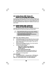
... diskette into the floppy drive. C. D. Formatting the floppy diskette will lose ALL data in your disk, please visit the below steps. E. Enter BIOS SETUP UTILITY Advanced screen IDE Configuration. STEP 3: Use "RAID Installation Guide" to [RAID]. If there is supposed to include SP4. When you see... Before installing Windows 2000 to your system, your disk is no need for boot devices selection appears. WARNING! Insert the ASRock Support CD into the floppy diskette. Please select CD- A. ROM as the boot device. Start to format and copy files [YN]? You can start to ...
... diskette into the floppy drive. C. D. Formatting the floppy diskette will lose ALL data in your disk, please visit the below steps. E. Enter BIOS SETUP UTILITY Advanced screen IDE Configuration. STEP 3: Use "RAID Installation Guide" to [RAID]. If there is supposed to include SP4. When you see... Before installing Windows 2000 to your system, your disk is no need for boot devices selection appears. WARNING! Insert the ASRock Support CD into the floppy diskette. Please select CD- A. ROM as the boot device. Start to format and copy files [YN]? You can start to ...

User Manual
Page 24
... being updated, the following selections: Main To set up the system time/date information Advanced To set up the advanced BIOS features H/W Monitor To display current hardware status Boot To set up the default system device to choose among the selections on . 3. You may not exactly match what ...you start up the security features Exit To exit the current screen or the BIOS SETUP UTILITY Use < > key or < > key to ...
... being updated, the following selections: Main To set up the system time/date information Advanced To set up the advanced BIOS features H/W Monitor To display current hardware status Boot To set up the default system device to choose among the selections on . 3. You may not exactly match what ...you start up the security features Exit To exit the current screen or the BIOS SETUP UTILITY Use < > key or < > key to ...

User Manual
Page 25
... specify the system time. 3.1.2 Navigation Keys Please check the following table for all the settings To save changes and exit the BIOS SETUP UTILITY To jump to specify the system date. 25 System Time [Hour:Minute:Second] Use this item to the Exit Screen... UTILITY, the Main screen will appear and display the system overview. BIOS SETUP UTILITY Main Advanced H/W Monitor Boot Security Exit System Overview System Time [17:00:09] System Date [Tue 08/09/2005] BIOS Version : 939NF4G-SATA2 BIOS P1.0 Processor Type : AMD Athlon(tm) 64 Processor 3400+ (64bit supported) Processor ...
... specify the system time. 3.1.2 Navigation Keys Please check the following table for all the settings To save changes and exit the BIOS SETUP UTILITY To jump to specify the system date. 25 System Time [Hour:Minute:Second] Use this item to the Exit Screen... UTILITY, the Main screen will appear and display the system overview. BIOS SETUP UTILITY Main Advanced H/W Monitor Boot Security Exit System Overview System Time [17:00:09] System Date [Tue 08/09/2005] BIOS Version : 939NF4G-SATA2 BIOS P1.0 Processor Type : AMD Athlon(tm) 64 Processor 3400+ (64bit supported) Processor ...

User Manual
Page 26
...USB Configuration. Setting wrong values in below sections may cause the system to malfunction. 3.3.1 CPU Configuration BIOS SETUP UTILITY Advanced CPU Configuration Overclock Mode CPU Frequency (MHz) PCIE Frequency (MHz) Boot Failure Guard CPU Spread Spectrum PCIE Spread Spectrum SATA Spread Spectrum HT Spread Spectrum Cool' n' Quiet ... 1985-2003, American Megatrends, Inc. The default value is [Auto]. The range is from 140MHz to select Overclock Mode. Main BIOS SETUP UTILITY Advanced H/W Monitor Boot Security Exit Advanced Settings WARNING : Setting wrong values in this to 300MHz.
...USB Configuration. Setting wrong values in below sections may cause the system to malfunction. 3.3.1 CPU Configuration BIOS SETUP UTILITY Advanced CPU Configuration Overclock Mode CPU Frequency (MHz) PCIE Frequency (MHz) Boot Failure Guard CPU Spread Spectrum PCIE Spread Spectrum SATA Spread Spectrum HT Spread Spectrum Cool' n' Quiet ... 1985-2003, American Megatrends, Inc. The default value is [Auto]. The range is from 140MHz to select Overclock Mode. Main BIOS SETUP UTILITY Advanced H/W Monitor Boot Security Exit Advanced Settings WARNING : Setting wrong values in this to 300MHz.

User Manual
Page 27
...this option to adjust PCIE frequency. However, it will be set to [Center Spread] as default. BIOS SETUP UTILITY Advanced CPU Configuration Overclock Mode CPU Frequency (MHz) PCIE Frequency (MHz) Boot Failure Guard CPU Spread Spectrum PCIE Spread Spectrum SATA Spread Spectrum HT Spread Spectrum Cool' n' Quiet ... will display Processor Maximum Multiplier for reference. otherwise, it is from [x8] up to [x25] but no higher than the value of Boot Failure Guard. PCIE Frequency (MHz) Use this item to enable or disable AMD's Cool 'n' QuietTM technology. The default value is set the...
...this option to adjust PCIE frequency. However, it will be set to [Center Spread] as default. BIOS SETUP UTILITY Advanced CPU Configuration Overclock Mode CPU Frequency (MHz) PCIE Frequency (MHz) Boot Failure Guard CPU Spread Spectrum PCIE Spread Spectrum SATA Spread Spectrum HT Spread Spectrum Cool' n' Quiet ... will display Processor Maximum Multiplier for reference. otherwise, it is from [x8] up to [x25] but no higher than the value of Boot Failure Guard. PCIE Frequency (MHz) Use this item to enable or disable AMD's Cool 'n' QuietTM technology. The default value is set the...
User Manual
Page 30
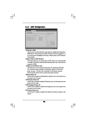
If [Power Off] is selected, the AC/power resumes and the system starts to boot up when the power recovers. If [Power On] is selected, the AC/power remains off mode. Select [Auto] will be hidden. RTC Alarm Power On ... the system from the power-soft-off when the power recovers. Ring-In Power On Use this item to turn on STR resume. 3.3.3 ACPI Configuration BIOS SETUP UTILITY Advanced ACPI Settings Suspend To RAM Repost Video on STR Resume Restore on the system. 30 PS/2 Keyboard Power On Use this item...
If [Power Off] is selected, the AC/power resumes and the system starts to boot up when the power recovers. If [Power On] is selected, the AC/power remains off mode. Select [Auto] will be hidden. RTC Alarm Power On ... the system from the power-soft-off when the power recovers. Ring-In Power On Use this item to turn on STR resume. 3.3.3 ACPI Configuration BIOS SETUP UTILITY Advanced ACPI Settings Suspend To RAM Repost Video on STR Resume Restore on the system. 30 PS/2 Keyboard Power On Use this item...

User Manual
Page 36
...emulate the I/O devices of the CPU temperature, motherboard temperature, CPU fan speed, chassis fan speed, and the critical voltage. BIOS SETUP UTILITY Main Advanced H/W Monitor Boot Security Exit Hardware Health Event Monitoring CPU Temperature M / B Temperature CPU Fan Speed Chassis Fan Speed Vcore + 3.30V ...2003, American Megatrends, Inc. 36 Legacy USB Support Use this section, it allows you to auto-detect; 3.3.8 USB Configuration BIOS SETUP UTILITY Advanced USB Configuration USB Controller USB 2.0 Support Legacy USB Support [Enabled] [Enabled] [Disabled] To enable or disable...
...emulate the I/O devices of the CPU temperature, motherboard temperature, CPU fan speed, chassis fan speed, and the critical voltage. BIOS SETUP UTILITY Main Advanced H/W Monitor Boot Security Exit Hardware Health Event Monitoring CPU Temperature M / B Temperature CPU Fan Speed Chassis Fan Speed Vcore + 3.30V ...2003, American Megatrends, Inc. 36 Legacy USB Support Use this section, it allows you to auto-detect; 3.3.8 USB Configuration BIOS SETUP UTILITY Advanced USB Configuration USB Controller USB 2.0 Support Legacy USB Support [Enabled] [Enabled] [Disabled] To enable or disable...

User Manual
Page 37
...v02.54 (C) Copyright 1985-2003, American Megatrends, Inc. 3.5.1 Boot Settings Configuration BIOS SETUP UTILITY Boot Boot Settings Configuration Boot From Network Bootup Num-Lock [Disabled] [On] To enable or disable the boot from network feature. +F1 F9 F10 ESC Select Screen Select ...configure the boot settings and the boot priority. Select Screen Select Item Enter Go to enable or disable the Boot From Network feature. Main Advanced BIOS SETUP UTILITY H/W Monitor Boot Security Exit Boot Settings Boot Settings Configuration 1st Boot Device 2nd Boot Device 3rd Boot Device Hard...
...v02.54 (C) Copyright 1985-2003, American Megatrends, Inc. 3.5.1 Boot Settings Configuration BIOS SETUP UTILITY Boot Boot Settings Configuration Boot From Network Bootup Num-Lock [Disabled] [On] To enable or disable the boot from network feature. +F1 F9 F10 ESC Select Screen Select ...configure the boot settings and the boot priority. Select Screen Select Item Enter Go to enable or disable the Boot From Network feature. Main Advanced BIOS SETUP UTILITY H/W Monitor Boot Security Exit Boot Settings Boot Settings Configuration 1st Boot Device 2nd Boot Device 3rd Boot Device Hard...

User Manual
Page 38
Select Screen Select Item Enter Change F1 General Help F9 Load Defaults F10 Save and Exit ESC Exit v02.54 (C) Copyright 1985-2003, American Megatrends, Inc. 38 BIOS SETUP UTILITY Main Advanced H/W Monitor Boot Security Exit Security Settings Supervisor Password : Not Installed User Password : Not Installed Change Supervisor Password Change User Password Install or Change the password. 3.6 Security Screen In this section, you may set or change the supervisor/user password for the system. For the user password, you may also clear it.
Select Screen Select Item Enter Change F1 General Help F9 Load Defaults F10 Save and Exit ESC Exit v02.54 (C) Copyright 1985-2003, American Megatrends, Inc. 38 BIOS SETUP UTILITY Main Advanced H/W Monitor Boot Security Exit Security Settings Supervisor Password : Not Installed User Password : Not Installed Change Supervisor Password Change User Password Install or Change the password. 3.6 Security Screen In this section, you may set or change the supervisor/user password for the system. For the user password, you may also clear it.

User Manual
Page 39
...to discard all the setup configurations. 39 Select Screen Select Item Enter Go to exit the BIOS SETUP UTILITY without saving any changes. Select [OK] to save the changes and exit the BIOS SETUP UTILITY. Select [OK] to load the default values for this option, it will pop...-out the following message, "Save configuration changes and exit setup?" 3.7 Exit Screen Main BIOS SETUP UTILITY Advanced H/W Monitro Boot Security Exit Exit Options Save Changes and Exit Discard Changes and Exit Discard Changes Load Optimal Defaults Exit system setup after ...
...to discard all the setup configurations. 39 Select Screen Select Item Enter Go to exit the BIOS SETUP UTILITY without saving any changes. Select [OK] to save the changes and exit the BIOS SETUP UTILITY. Select [OK] to load the default values for this option, it will pop...-out the following message, "Save configuration changes and exit setup?" 3.7 Exit Screen Main BIOS SETUP UTILITY Advanced H/W Monitro Boot Security Exit Exit Options Save Changes and Exit Discard Changes and Exit Discard Changes Load Optimal Defaults Exit system setup after ...

Quick Installation Guide
Page 12
Short Open Jumper Setting PS2_USB_PW1 Short pin2, pin3 to clear the CMOS when you just finish updating the BIOS, you must boot up events. English 12 ASRock 939NF4G-SATA2 Motherboard To clear and reset the system parameters to clear the data in CMOS includes system setup information such ...unplug the power cord from the power supply. If you need to enable (see p.8, No. 19) Default Clear CMOS Note: CLRCMOS1 allows you update the BIOS. Clear CMOS Jumper (CLRCMOS1) (see p.2, No. 1) +5VSB (standby) for 5 seconds. JR1 JL1 Jumper (see p.2, No. 27) Note: If...
Short Open Jumper Setting PS2_USB_PW1 Short pin2, pin3 to clear the CMOS when you just finish updating the BIOS, you must boot up events. English 12 ASRock 939NF4G-SATA2 Motherboard To clear and reset the system parameters to clear the data in CMOS includes system setup information such ...unplug the power cord from the power supply. If you need to enable (see p.8, No. 19) Default Clear CMOS Note: CLRCMOS1 allows you update the BIOS. Clear CMOS Jumper (CLRCMOS1) (see p.2, No. 1) +5VSB (standby) for 5 seconds. JR1 JL1 Jumper (see p.2, No. 27) Note: If...

