RAID Installation Guide
Page 2
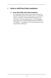
This section will guide you how to SATA Hard Disks Installation 1.1 Serial ATA (SATA) Hard Disks Installation This motherboard adopts nVidia nForce3 chipset that supports Serial ATA (SATA) hard disks with RAID functions, including RAID 0, RAID 1, and JBOD. You may install SATA hard disks on SATA ports. 2 1. Guide to create RAID on this motherboard for internal storage devices. For SATA installation guide, please refer to Serial ATA (SATA) Hard Disks Installation of "U ser Manual " in the support CD.
This section will guide you how to SATA Hard Disks Installation 1.1 Serial ATA (SATA) Hard Disks Installation This motherboard adopts nVidia nForce3 chipset that supports Serial ATA (SATA) hard disks with RAID functions, including RAID 0, RAID 1, and JBOD. You may install SATA hard disks on SATA ports. 2 1. Guide to create RAID on this motherboard for internal storage devices. For SATA installation guide, please refer to Serial ATA (SATA) Hard Disks Installation of "U ser Manual " in the support CD.
RAID Installation Guide
Page 3
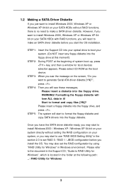
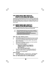
..., Windows XP or Windows XP 64-bit on your system, or you may start to use "RAID BIOS Setting Utility" in it! STEP 1: Insert the Support CD into your optical drive to boot your system. (Do NOT insert any floppy diskette into the floppy drive. Please select CD-ROM as the... without setting the RAID configuration on your SATA HDDs without RAID functions, there is located in Windows environment. Please refer to the document in the Support CD, "Guide to RAID Utility for boot devices selection appears. STEP 3: When you see these messages, Please insert a diskette into the floppy drive at this...
..., Windows XP or Windows XP 64-bit on your system, or you may start to use "RAID BIOS Setting Utility" in it! STEP 1: Insert the Support CD into your optical drive to boot your system. (Do NOT insert any floppy diskette into the floppy drive. Please select CD-ROM as the... without setting the RAID configuration on your SATA HDDs without RAID functions, there is located in Windows environment. Please refer to the document in the Support CD, "Guide to RAID Utility for boot devices selection appears. STEP 3: When you see these messages, Please insert a diskette into the floppy drive at this...
RAID Installation Guide
Page 4
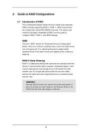
... configure RAID 0, RAID 1, and JBOD settings. For optimal performance, please install identical drives of Independent Disks", which is called data striping that integrates RAID controller supporting RAID 0 / RAID 1 / JBOD function with two independent Serial ATA (SATA) channels. RAID 0 (Data Striping) RAID 0 is a method combining two or more hard disk drives into...
... configure RAID 0, RAID 1, and JBOD settings. For optimal performance, please install identical drives of Independent Disks", which is called data striping that integrates RAID controller supporting RAID 0 / RAID 1 / JBOD function with two independent Serial ATA (SATA) channels. RAID 0 (Data Striping) RAID 0 is a method combining two or more hard disk drives into...

RAID Installation Guide
Page 5
... then proceeds to the entire system since the disk array management software will affect the entire array. When any member disk fails, it does not support fault tolerance. 5
... then proceeds to the entire system since the disk array management software will affect the entire array. When any member disk fails, it does not support fault tolerance. 5
RAID Utility for Windows Guide
Page 1
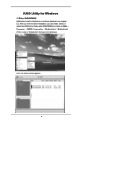
After you finish the driver installation, you can create, delete, or rebuild any RAID array. Enter NVRAIDMAN RAID driver is also a "Mediashield" shortcut on the desktop.) Then, the below screen appears. 1 Please enter NVRAIDMAN by clicking on Start Programs NVIDIA Corporation Mediashield Mediashield. (There is built in nVidia ALL in one driver provided in our support CD. RAID Utility for Windows 1.
After you finish the driver installation, you can create, delete, or rebuild any RAID array. Enter NVRAIDMAN RAID driver is also a "Mediashield" shortcut on the desktop.) Then, the below screen appears. 1 Please enter NVRAIDMAN by clicking on Start Programs NVIDIA Corporation Mediashield Mediashield. (There is built in nVidia ALL in one driver provided in our support CD. RAID Utility for Windows 1.
RAID Utility for Windows Guide
Page 2
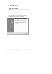
Boot to use are RAID enabled. 2. To create a twodisk Striped Array do the following screen will appear. 2 Go to the system BIOS and make sure that the drives that you want to Windows and launch the NVRAIDMAN application. 3. Create Array and the following . 1. Creating RAID Arrays Creating RAID 0 (Striping) NVRAIDMAN can be used to create a striped array from one disk up to the maximum supported number of disks in the system. 2.
Boot to use are RAID enabled. 2. To create a twodisk Striped Array do the following screen will appear. 2 Go to the system BIOS and make sure that the drives that you want to Windows and launch the NVRAIDMAN application. 3. Create Array and the following . 1. Creating RAID Arrays Creating RAID 0 (Striping) NVRAIDMAN can be used to create a striped array from one disk up to the maximum supported number of disks in the system. 2.

User Manual
Page 5
... might be updated, the content of this manual will be subject to quality and endurance. ASRock website http://www.asrock.com 1.1 Package Contents 1 x ASRock 939NF4G-SATA2 Motherboard (Micro ATX Form Factor: 9.6-in x 8.8-in, 24.4 cm x 22.4 cm) 1 x ASRock 939NF4G-SATA2 Quick Installation Guide 1 x ASRock 939NF4G-SATA2 Support CD 1 x Ultra ATA 66/100/133 IDE Ribbon Cable (80-conductor) 1 x 3.5-in Floppy Drive Ribbon...
... might be updated, the content of this manual will be subject to quality and endurance. ASRock website http://www.asrock.com 1.1 Package Contents 1 x ASRock 939NF4G-SATA2 Motherboard (Micro ATX Form Factor: 9.6-in x 8.8-in, 24.4 cm x 22.4 cm) 1 x ASRock 939NF4G-SATA2 Quick Installation Guide 1 x ASRock 939NF4G-SATA2 Support CD 1 x Ultra ATA 66/100/133 IDE Ribbon Cable (80-conductor) 1 x 3.5-in Floppy Drive Ribbon...

User Manual
Page 6
.../2 Mouse Port - 1 x PS/2 Keyboard Port - 1 x VGA Port - 1 x Parallel Port (ECP/EPP Support) - 4 x Ready-to-Use USB 2.0 Ports - 1 x RJ-45 Port - Supports Hyper-Transport Technology - Boot Failure Guard (B.F.G.) - 2 x PCI slots - 1 x PCI Express x 16 slot - 1 x PCI Express x 1 slot - 1 x AMR slot - ASRock U-COP (see CAUTION 4) - Supports Untied Overclocking Technology (see CAUTION 6) 6 Realtek ALC850 7.1 channel AC'97 audio...
.../2 Mouse Port - 1 x PS/2 Keyboard Port - 1 x VGA Port - 1 x Parallel Port (ECP/EPP Support) - 4 x Ready-to-Use USB 2.0 Ports - 1 x RJ-45 Port - Supports Hyper-Transport Technology - Boot Failure Guard (B.F.G.) - 2 x PCI slots - 1 x PCI Express x 16 slot - 1 x PCI Express x 1 slot - 1 x AMR slot - ASRock U-COP (see CAUTION 4) - Supports Untied Overclocking Technology (see CAUTION 6) 6 Realtek ALC850 7.1 channel AC'97 audio...
User Manual
Page 7
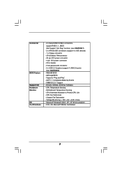
...® Windows® 2000 / XP / XP 64-bit compliant - Connector BIOS Feature Support CD Hardware Monitor OS Certifications - 2 x Serial ATAII 3.0Gb/s connectors, support RAID 0, 1, JBOD (Not Support "Hot Plug" function) (see CAUTION 8) - 4Mb AMI BIOS - AMI Legal BIOS ...Chassis FAN connector - 20 pin ATX power connector - 4 pin 12V power connector - SMBIOS 2.3.1 Support - Front panel audio connector - 2 x USB 2.0 headers (support 4 USB 2.0 ports) (see CAUTION 7) - 2 x ATA133 IDE connectors (support 4 x IDE devices) - 1 x Floppy connector - Voltage Monitoring: +12V, +5V, +3.3V, Vcore ...
...® Windows® 2000 / XP / XP 64-bit compliant - Connector BIOS Feature Support CD Hardware Monitor OS Certifications - 2 x Serial ATAII 3.0Gb/s connectors, support RAID 0, 1, JBOD (Not Support "Hot Plug" function) (see CAUTION 8) - 4Mb AMI BIOS - AMI Legal BIOS ...Chassis FAN connector - 20 pin ATX power connector - 4 pin 12V power connector - SMBIOS 2.3.1 Support - Front panel audio connector - 2 x USB 2.0 headers (support 4 USB 2.0 ports) (see CAUTION 7) - 2 x ATA133 IDE connectors (support 4 x IDE devices) - 1 x Floppy connector - Voltage Monitoring: +12V, +5V, +3.3V, Vcore ...
User Manual
Page 8
...'s Cool 'n' QuietTM technology under Microsoft® Windows® XP SP1 / 2000 SP4. 8 Power Management for proper connection. 7. This motherboard supports Dual Channel Memory Technology. While CPU overheat is strongly recommended to the SATAII connector. Please check the table on page 41 to SATA 1.5Gb... to downgrade the SATAII hard disk to SATA hard disk (from SATAII 3Gb/s down to enable AMD's Cool 'n' QuietTM technology. You can support AMD's Cool 'n' QuietTM technology, please check AMD's website for proper installation. 4. Besides, you resume the system, please check if the...
...'s Cool 'n' QuietTM technology under Microsoft® Windows® XP SP1 / 2000 SP4. 8 Power Management for proper connection. 7. This motherboard supports Dual Channel Memory Technology. While CPU overheat is strongly recommended to the SATAII connector. Please check the table on page 41 to SATA 1.5Gb... to downgrade the SATAII hard disk to SATA hard disk (from SATAII 3Gb/s down to enable AMD's Cool 'n' QuietTM technology. You can support AMD's Cool 'n' QuietTM technology, please check AMD's website for proper installation. 4. Besides, you resume the system, please check if the...

User Manual
Page 13
... DDR2; If only one memory module or three memory modules are installed in the slots of Memory Modules (DIMM) 939NF4G-SATA2 motherboard provides four 184-pin DDR (Double Data Rate) DIMM slots, and supports Dual Channel Memory Technology. Blue slots; In other words, install them in the DDR DIMM slots on this motherboard...
... DDR2; If only one memory module or three memory modules are installed in the slots of Memory Modules (DIMM) 939NF4G-SATA2 motherboard provides four 184-pin DDR (Double Data Rate) DIMM slots, and supports Dual Channel Memory Technology. Blue slots; In other words, install them in the DDR DIMM slots on this motherboard...

User Manual
Page 15
... that the power supply is switched off or the power cord is unplugged. Replace the system cover. 2.5 Easy Multi Monitor Feature This motherboard supports Multi Monitor upgrade. The default value of the expansion card and make sure that you plan to enable the function of onboard VGA, please ...VGA cards and VGA card drivers to insert an ASRock MR card with the slot and press firmly until the card is used to the chassis with x16 lane width graphics cards. With the internal onboard VGA and the external add-on 939NF4G-SATA2 motherboard. Please read the documentation of "Share Memory...
... that the power supply is switched off or the power cord is unplugged. Replace the system cover. 2.5 Easy Multi Monitor Feature This motherboard supports Multi Monitor upgrade. The default value of the expansion card and make sure that you plan to enable the function of onboard VGA, please ...VGA cards and VGA card drivers to insert an ASRock MR card with the slot and press firmly until the card is used to the chassis with x16 lane width graphics cards. With the internal onboard VGA and the external add-on 939NF4G-SATA2 motherboard. Please read the documentation of "Share Memory...

User Manual
Page 17
... end to the instruction of the motherboard! • Floppy Connector (33-pin FLOPPY1) (see p.9, No. 12) SATAII_2 SATAII_1 These Serial ATA II (SATA II) connectors support SATA II or SATA hard disk for the details. Do NOT place jumper caps over the headers and connectors will cause permanent damage of your...
... end to the instruction of the motherboard! • Floppy Connector (33-pin FLOPPY1) (see p.9, No. 12) SATAII_2 SATAII_1 These Serial ATA II (SATA II) connectors support SATA II or SATA hard disk for the details. Do NOT place jumper caps over the headers and connectors will cause permanent damage of your...

User Manual
Page 18
... on the I /O panel are not sufficient, this USB 2.0 header is available to support 2 additional USB 2.0 ports. USB 2.0 Header (9-pin USB45) (see p.9 No. 17) USB_PWR P-7 P+7 GND DUMMY 1 GND P+6 P-6 USB_PWR ASRock 8CH I /O accommodates 4 default USB 2.0 ports. USB 2.0 Header (9-pin USB67) ...(see p.9 No. 18) USB_PWR P-5 P+5 GND DUMMY 1 GND P+4 P-4 USB_PWR ASRock 8CH I /O accommodates 4 default USB 2.0 ports. O U T- R MIC-POWER MIC This is available to support 2 additional USB 2.0 ports. Front Panel Audio Header (9-pin AUDIO1) (see p.9 No. 30) IRTX +...
... on the I /O panel are not sufficient, this USB 2.0 header is available to support 2 additional USB 2.0 ports. USB 2.0 Header (9-pin USB45) (see p.9 No. 17) USB_PWR P-7 P+7 GND DUMMY 1 GND P+6 P-6 USB_PWR ASRock 8CH I /O accommodates 4 default USB 2.0 ports. USB 2.0 Header (9-pin USB67) ...(see p.9 No. 18) USB_PWR P-5 P+5 GND DUMMY 1 GND P+4 P-4 USB_PWR ASRock 8CH I /O accommodates 4 default USB 2.0 ports. O U T- R MIC-POWER MIC This is available to support 2 additional USB 2.0 ports. Front Panel Audio Header (9-pin AUDIO1) (see p.9 No. 30) IRTX +...

User Manual
Page 19
... wire to this header if the Game port bracket is necessary to connect a power supply with ATX 12V plug to this connector. This COM1 connector supports a serial port module. ATX 12V Power Connector (4-pin ATX12V1) (see p.9 No. 2) Game Port Header (15-pin GAME1) (see p.9 No. 23) Serial port connector (9-pin COM1...
... wire to this header if the Game port bracket is necessary to connect a power supply with ATX 12V plug to this connector. This COM1 connector supports a serial port module. ATX 12V Power Connector (4-pin ATX12V1) (see p.9 No. 2) Game Port Header (15-pin GAME1) (see p.9 No. 23) Serial port connector (9-pin COM1...

User Manual
Page 20
... of SATAII hard disks may not be enabled. Western Digital 7531 8642 If pin 5 and pin 6 are just for details: http://www.hitachigst.com/hdd/support/download.htm The above examples are shorted, SATA 1.5Gb/s will be at SATAII mode. On the other hand, if you want to enable SATAII 3.0Gb...
... of SATAII hard disks may not be enabled. Western Digital 7531 8642 If pin 5 and pin 6 are just for details: http://www.hitachigst.com/hdd/support/download.htm The above examples are shorted, SATA 1.5Gb/s will be at SATAII mode. On the other hand, if you want to enable SATAII 3.0Gb...

User Manual
Page 21
2.9 Serial ATA (SATA) / Serial ATAII (SATAII) Hard Disks Installation This motherboard adopts nVidia nForce 410 MCP southbridge chipset that supports Serial ATA (SATA) / Serial ATAII (SATAII) hard disks and RAID functions. This section will guide you to the SATA / SATAII hard disk. You may install ...
2.9 Serial ATA (SATA) / Serial ATAII (SATAII) Hard Disks Installation This motherboard adopts nVidia nForce 410 MCP southbridge chipset that supports Serial ATA (SATA) / Serial ATAII (SATAII) hard disks and RAID functions. This section will guide you to the SATA / SATAII hard disk. You may install ...
User Manual
Page 22
..., your SATA / SATAII HDDs without RAID functions, you don't have to make a SATA / SATAII driver diskette. Start to [RAID]. STEP 2: Set Up BIOS. Insert the ASRock Support CD into the floppy drive. ROM as the boot device. Set the "SATAII Operation Mode" option from [non-RAID] to format and copy files [YN...
..., your SATA / SATAII HDDs without RAID functions, you don't have to make a SATA / SATAII driver diskette. Start to [RAID]. STEP 2: Set Up BIOS. Insert the ASRock Support CD into the floppy drive. ROM as the boot device. Set the "SATAII Operation Mode" option from [non-RAID] to format and copy files [YN...
User Manual
Page 23
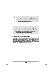
...RAID] first. Therefore, CPU FSB is untied during overclocking, but PCI and PCIE buses are in the Support CD for Windows Guide 2.12 Untied Overclocking Technology This motherboard supports Untied Overclocing Technology, which means during overclocking, FSB enjoys better margin due to fixed PCI / PCIE buses.... Please refer to the document in the Support CD, "Guide to nVidia RAID Utility for Windows", which is located in the folder at the following path: .. \Information\Manual\RAID ...
...RAID] first. Therefore, CPU FSB is untied during overclocking, but PCI and PCIE buses are in the Support CD for Windows Guide 2.12 Untied Overclocking Technology This motherboard supports Untied Overclocing Technology, which means during overclocking, FSB enjoys better margin due to fixed PCI / PCIE buses.... Please refer to the document in the Support CD, "Guide to nVidia RAID Utility for Windows", which is located in the folder at the following path: .. \Information\Manual\RAID ...

User Manual
Page 25
... Advanced H/W Monitor Boot Security Exit System Overview System Time [17:00:09] System Date [Tue 08/09/2005] BIOS Version : 939NF4G-SATA2 BIOS P1.0 Processor Type : AMD Athlon(tm) 64 Processor 3400+ (64bit supported) Processor Speed : 2200 MHz Microcode Update : F7A/3A L1 Cache Size : 128KB L2 Cache Size : 512KB Total Memory DDR...
... Advanced H/W Monitor Boot Security Exit System Overview System Time [17:00:09] System Date [Tue 08/09/2005] BIOS Version : 939NF4G-SATA2 BIOS P1.0 Processor Type : AMD Athlon(tm) 64 Processor 3400+ (64bit supported) Processor Speed : 2200 MHz Microcode Update : F7A/3A L1 Cache Size : 128KB L2 Cache Size : 512KB Total Memory DDR...


