User Manual
Page 3
...37 3.6 Security Screen 38 3.7 Exit Screen 39 3 Installation 11 Pre-installation Precautions 11 2.1 CPU Installation 12 2.2 Installation of CPU Fan and Heatsink 12 2.3 Installation of Memory Modules (DIMM 13 2.4 Expansion Slots (PCI, PCI Express, and AMR Slots 15 2.5 Easy Multi Monitor Feature 15 2.6 Jumpers Setup 16 2.7 Onboard Headers and Connectors ... 23 2.11 Installing Windows 2000 / XP / XP 64-bit With RAID Functions. 23 2.12 Untied Overclocking Technology 23 3 . Introduction 5 1.1 Package Contents 5 1.2 Specifications 6 1.3 Motherboard Layout 9 1.4 ASRock 8CH I/O 10 2 .
...37 3.6 Security Screen 38 3.7 Exit Screen 39 3 Installation 11 Pre-installation Precautions 11 2.1 CPU Installation 12 2.2 Installation of CPU Fan and Heatsink 12 2.3 Installation of Memory Modules (DIMM 13 2.4 Expansion Slots (PCI, PCI Express, and AMR Slots 15 2.5 Easy Multi Monitor Feature 15 2.6 Jumpers Setup 16 2.7 Onboard Headers and Connectors ... 23 2.11 Installing Windows 2000 / XP / XP 64-bit With RAID Functions. 23 2.12 Untied Overclocking Technology 23 3 . Introduction 5 1.1 Package Contents 5 1.2 Specifications 6 1.3 Motherboard Layout 9 1.4 ASRock 8CH I/O 10 2 .

User Manual
Page 5
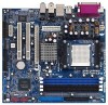
... modifications of this manual will be subject to quality and endurance. You may find the latest memory and CPU support lists on ASRock website without notice. Introduction Thank you for purchasing ASRock 939NF4G-SATA2 motherboard, a reliable motherboard produced under ASRock's consistently stringent quality control. Because the motherboard specifications and the BIOS software might be updated, the...
... modifications of this manual will be subject to quality and endurance. You may find the latest memory and CPU support lists on ASRock website without notice. Introduction Thank you for purchasing ASRock 939NF4G-SATA2 motherboard, a reliable motherboard produced under ASRock's consistently stringent quality control. Because the motherboard specifications and the BIOS software might be updated, the...

User Manual
Page 6
...Speed: 10/100 Ethernet - Realtek ALC850 7.1 channel AC'97 audio codec - Supports Hyper-Transport Technology - ASRock U-COP (see CAUTION 4) - Supports Wake-On-LAN ASRock 8CH I /O - Micro ATX Form Factor: 9.6-in x 8.8-in /Front Speaker/Microphone (see CAUTION ...1) - Supports Untied Overclocking Technology (see CAUTION 3) - 4 x DDR DIMM slots - Max. shared memory 128MB - 1.2 Specifications Platform CPU Chipset Memory Hybrid Booster Expansion Slot Graphics Audio...
...Speed: 10/100 Ethernet - Realtek ALC850 7.1 channel AC'97 audio codec - Supports Hyper-Transport Technology - ASRock U-COP (see CAUTION 4) - Supports Wake-On-LAN ASRock 8CH I /O - Micro ATX Form Factor: 9.6-in x 8.8-in /Front Speaker/Microphone (see CAUTION ...1) - Supports Untied Overclocking Technology (see CAUTION 3) - 4 x DDR DIMM slots - Max. shared memory 128MB - 1.2 Specifications Platform CPU Chipset Memory Hybrid Booster Expansion Slot Graphics Audio...
User Manual
Page 8
...5. Before you resume the system, please check if the CPU fan on page 23 for details. 3. Before you implement Dual Channel Memory Technology, make sure to the SATAII connector. For power-saving's sake, it is not recommended to enable AMD's Cool 'n' QuietTM ...channel, and 8-channel modes. Please read the "SATAII Hard Disk Setup Guide" on page 41 to SATAII mode. This motherboard supports Dual Channel Memory Technology. You can support AMD's Cool 'n' QuietTM technology, please check AMD's website for proper installation. 4. Although this motherboard offers stepless control,...
...5. Before you resume the system, please check if the CPU fan on page 23 for details. 3. Before you implement Dual Channel Memory Technology, make sure to the SATAII connector. For power-saving's sake, it is not recommended to enable AMD's Cool 'n' QuietTM ...channel, and 8-channel modes. Please read the "SATAII Hard Disk Setup Guide" on page 41 to SATAII mode. This motherboard supports Dual Channel Memory Technology. You can support AMD's Cool 'n' QuietTM technology, please check AMD's website for proper installation. 4. Although this motherboard offers stepless control,...

User Manual
Page 13
...see p.9 No.6) or identical DDR DIMM pair in all four slots. 1. In other words, you always need to the Dual Channel Memory Configuration Table below. If a pair of memory modules is NOT installed in the DDR DIMM slots on this motherboard, it is unable to activate the Dual Channel... be activated. This motherboard also allows you want to install two memory modules, for example, installing a pair of the same color. If you to install identical DDR DIMM pair in the set of Memory Modules (DIMM) 939NF4G-SATA2 motherboard provides four 184-pin DDR (Double Data Rate) DIMM slots...
...see p.9 No.6) or identical DDR DIMM pair in all four slots. 1. In other words, you always need to the Dual Channel Memory Configuration Table below. If a pair of memory modules is NOT installed in the DDR DIMM slots on this motherboard, it is unable to activate the Dual Channel... be activated. This motherboard also allows you want to install two memory modules, for example, installing a pair of the same color. If you to install identical DDR DIMM pair in the set of Memory Modules (DIMM) 939NF4G-SATA2 motherboard provides four 184-pin DDR (Double Data Rate) DIMM slots...

User Manual
Page 15
PCI Slots: PCI slots are 2 PCI Express slots, 2 PCI slots and 1 AMR slot on 939NF4G-SATA2 motherboard. Remove the bracket facing the slot that have the 32-bit PCI interface. Step 5. Fasten the card to the chassis with v.92 Modem functionality. ... slot: The AMR slot is [Auto], which will disable onboard VGA function when installing VGA card. Please read the documentation of "Share Memory" is used to insert an ASRock MR card with screws. Step 2. Please note that the power supply is switched off or the power cord is completely seated on PCI...
PCI Slots: PCI slots are 2 PCI Express slots, 2 PCI slots and 1 AMR slot on 939NF4G-SATA2 motherboard. Remove the bracket facing the slot that have the 32-bit PCI interface. Step 5. Fasten the card to the chassis with v.92 Modem functionality. ... slot: The AMR slot is [Auto], which will disable onboard VGA function when installing VGA card. Please read the documentation of "Share Memory" is used to insert an ASRock MR card with screws. Step 2. Please note that the power supply is switched off or the power cord is completely seated on PCI...

User Manual
Page 24
... by turning the system off and then back on the system chassis. 3. If you see on the motherboard stores the BIOS SETUP UTILITY. The Flash Memory on your system. You may not exactly match what you wish to get into the sub screen. 24 BIOS SETUP UTILITY 3.1 Introduction This section explains...
... by turning the system off and then back on the system chassis. 3. If you see on the motherboard stores the BIOS SETUP UTILITY. The Flash Memory on your system. You may not exactly match what you wish to get into the sub screen. 24 BIOS SETUP UTILITY 3.1 Introduction This section explains...

User Manual
Page 25
... UTILITY Main Advanced H/W Monitor Boot Security Exit System Overview System Time [17:00:09] System Date [Tue 08/09/2005] BIOS Version : 939NF4G-SATA2 BIOS P1.0 Processor Type : AMD Athlon(tm) 64 Processor 3400+ (64bit supported) Processor Speed : 2200 MHz Microcode Update : F7A/3A L1... Cache Size : 128KB L2 Cache Size : 512KB Total Memory DDR 1 DDR 2 DDR 3 DDR 4 : 512MB with 64MB shared memory Dual-Channel Memory Mode : 256MB/166MHz (DDR333) : 256MB/166MHz (DDR333) : None : None Use [Enter], [TAB] or [SHIFT-TAB...
... UTILITY Main Advanced H/W Monitor Boot Security Exit System Overview System Time [17:00:09] System Date [Tue 08/09/2005] BIOS Version : 939NF4G-SATA2 BIOS P1.0 Processor Type : AMD Athlon(tm) 64 Processor 3400+ (64bit supported) Processor Speed : 2200 MHz Microcode Update : F7A/3A L1... Cache Size : 128KB L2 Cache Size : 512KB Total Memory DDR 1 DDR 2 DDR 3 DDR 4 : 512MB with 64MB shared memory Dual-Channel Memory Mode : 256MB/166MHz (DDR333) : 256MB/166MHz (DDR333) : None : None Use [Enter], [TAB] or [SHIFT-TAB...

User Manual
Page 26
... Failure Guard CPU Spread Spectrum PCIE Spread Spectrum SATA Spread Spectrum HT Spread Spectrum Cool' n' Quiet Processor Maximum Multiplier Processor Maximum Voltage Multiplier/Voltage Change Memory Clock Flexibility Option Bank Interleaving Burst Length CAS Latency (CL) TRCD TRAS [Auto] [200] [100] [Enabled] [Center Spread] [Enabled] [Enabled] [Center Spread] [Enabled] x11 1.550...
... Failure Guard CPU Spread Spectrum PCIE Spread Spectrum SATA Spread Spectrum HT Spread Spectrum Cool' n' Quiet Processor Maximum Multiplier Processor Maximum Voltage Multiplier/Voltage Change Memory Clock Flexibility Option Bank Interleaving Burst Length CAS Latency (CL) TRCD TRAS [Auto] [200] [100] [Enabled] [Center Spread] [Enabled] [Enabled] [Center Spread] [Enabled] x11 1.550...

User Manual
Page 27
... Spectrum PCIE Spread Spectrum SATA Spread Spectrum HT Spread Spectrum Cool' n' Quiet Processor Maximum Multiplier Processor Maximum Voltage Multiplier/Voltage Change Processor Multiplier Processor Voltage Memory Clock Flexibility Option Bank Interleaving Burst Length [Auto] [200] [100] [Enabled] [Center Spread] [Enabled] [Enabled] [Center Spread] [Enabled] x11 1.550 V [Manual] [x8] [1.500V] [Auto] [Disabled...
... Spectrum PCIE Spread Spectrum SATA Spread Spectrum HT Spread Spectrum Cool' n' Quiet Processor Maximum Multiplier Processor Maximum Voltage Multiplier/Voltage Change Processor Multiplier Processor Voltage Memory Clock Flexibility Option Bank Interleaving Burst Length [Auto] [200] [100] [Enabled] [Center Spread] [Enabled] [Enabled] [Center Spread] [Enabled] x11 1.550 V [Manual] [x8] [1.500V] [Auto] [Disabled...

User Manual
Page 28
...Processor Voltage This item will show when "Multiplier/Voltage Change" is set the value from [1.550V] down to adjust TRAS values. Bank Interleaving Interleaving allows memory accesses to [Manual]; The default value is [Auto]. The default value is [Disabled]. The default value is [Auto]. You may set to be... will be [x11] even if you install 4G DDR DIMM, please select [Enabled]. Configuration options: [Auto], [2T], [1T]. If your OS supports memory above 4G, and you set by the code using [Auto]. However, for MA timing. TRCD Use this to adjust the value of this item to...
...Processor Voltage This item will show when "Multiplier/Voltage Change" is set the value from [1.550V] down to adjust TRAS values. Bank Interleaving Interleaving allows memory accesses to [Manual]; The default value is [Auto]. The default value is [Disabled]. The default value is [Auto]. You may set to be... will be [x11] even if you install 4G DDR DIMM, please select [Enabled]. Configuration options: [Auto], [2T], [1T]. If your OS supports memory above 4G, and you set by the code using [Auto]. However, for MA timing. TRCD Use this to adjust the value of this item to...

User Manual
Page 29
...Speed This feature allows you to NB link frequency. NB Link Width This feature allows you to NB link width. Share Memory This allows you selecting CPU to set share memory feature. The default value is [PCI]. Configuration options: [Auto], [8 bit], and [16 bit]. NB - DRAM ... This feature allows you to select DRAM voltage. 3.3.2 Chipset Configuration BIOS SETUP UTILITY Advanced Chipset Settings Onboard LAN Onboard AC97 Audio Onboard AC97 Modem Share Memory Primary Graphics Adapter [Enabled] [Auto] [Auto] [Auto] [PCI] CPU-NB Link Speed CPU-NB Kink Width NB-SB Link Speed [Auto] ...
...Speed This feature allows you to NB link frequency. NB Link Width This feature allows you to NB link width. Share Memory This allows you selecting CPU to set share memory feature. The default value is [PCI]. Configuration options: [Auto], [8 bit], and [16 bit]. NB - DRAM ... This feature allows you to select DRAM voltage. 3.3.2 Chipset Configuration BIOS SETUP UTILITY Advanced Chipset Settings Onboard LAN Onboard AC97 Audio Onboard AC97 Modem Share Memory Primary Graphics Adapter [Enabled] [Auto] [Auto] [Auto] [PCI] CPU-NB Link Speed CPU-NB Kink Width NB-SB Link Speed [Auto] ...

Quick Installation Guide
Page 2
... Internal Audio Connector: CD1 (Black) 14 Chassis Speaker Header (SPEAKER 1) 31 ATX Power Connector (ATXPWR1) 15 Chassis Fan Connector (CHA_FAN1) 32 Serial Port Connector (COM1) 2 ASRock 939NF4G-SATA2 Motherboard Blue) 22 Flash Memory 7 2 x 184-pin DDR DIMM Slots 23 Game Port Header (GAME1) (Dual Channel B: DDR3, DDR4;
... Internal Audio Connector: CD1 (Black) 14 Chassis Speaker Header (SPEAKER 1) 31 ATX Power Connector (ATXPWR1) 15 Chassis Fan Connector (CHA_FAN1) 32 Serial Port Connector (COM1) 2 ASRock 939NF4G-SATA2 Motherboard Blue) 22 Flash Memory 7 2 x 184-pin DDR DIMM Slots 23 Game Port Header (GAME1) (Dual Channel B: DDR3, DDR4;
Quick Installation Guide
Page 4
... of the motherboard can be available on ASRock website as well. You may find the latest memory and CPU support lists on ASRock website without notice. ASRock website http://www.asrock.com 1.1 Package Contents 1 x ASRock 939NF4G-SATA2 Motherboard (Micro ATX Form Factor: 9.6-in x 8.8-in, 24.4 cm x 22.4 cm) 1 x ASRock 939NF4G-SATA2 Quick Installation Guide 1 x ASRock 939NF4G-SATA2 Support CD 1 x Ultra ATA 66/100/133...
... of the motherboard can be available on ASRock website as well. You may find the latest memory and CPU support lists on ASRock website without notice. ASRock website http://www.asrock.com 1.1 Package Contents 1 x ASRock 939NF4G-SATA2 Motherboard (Micro ATX Form Factor: 9.6-in x 8.8-in, 24.4 cm x 22.4 cm) 1 x ASRock 939NF4G-SATA2 Quick Installation Guide 1 x ASRock 939NF4G-SATA2 Support CD 1 x Ultra ATA 66/100/133...

Quick Installation Guide
Page 5
... (see CAUTION 5) - Micro ATX Form Factor: 9.6-in x 8.8-in /Front Speaker/Microphone (see CAUTION 3) - 4 x DDR DIMM slots - capacity: 4GB Hybrid Booster - Dual Channel DDR Memory Technology (see CAUTION 6) 5 ASRock 939NF4G-SATA2 Motherboard English Realtek ALC850 7.1 channel AC'97 audio codec LAN - Supports Hyper-Transport Technology Chipset - Support DDR400 / 333 / 266 - CPU Multiplier - Integrated NV44 graphics...
... (see CAUTION 5) - Micro ATX Form Factor: 9.6-in x 8.8-in /Front Speaker/Microphone (see CAUTION 3) - 4 x DDR DIMM slots - capacity: 4GB Hybrid Booster - Dual Channel DDR Memory Technology (see CAUTION 6) 5 ASRock 939NF4G-SATA2 Motherboard English Realtek ALC850 7.1 channel AC'97 audio codec LAN - Supports Hyper-Transport Technology Chipset - Support DDR400 / 333 / 266 - CPU Multiplier - Integrated NV44 graphics...

Quick Installation Guide
Page 7
..." in the Support CD to SATAII connector directly. 8. Frequencies other than the recommended CPU bus frequencies may cause the instability of memory modules on page 3 for details. 2. For audio output, this motherboard supports both stereo and mono modes. You can support AMD...from SATAII 3Gb/s down to enable AMD's Cool 'n' QuietTM technology under Microsoft® Windows® XP SP1 / 2000 SP4. 7 ASRock 939NF4G-SATA2 Motherboard English Besides, you install the PC system. 6. Although this motherboard offers stepless control, it is strongly recommended to SATA 1.5Gb/s),...
..." in the Support CD to SATAII connector directly. 8. Frequencies other than the recommended CPU bus frequencies may cause the instability of memory modules on page 3 for details. 2. For audio output, this motherboard supports both stereo and mono modes. You can support AMD...from SATAII 3Gb/s down to enable AMD's Cool 'n' QuietTM technology under Microsoft® Windows® XP SP1 / 2000 SP4. 7 ASRock 939NF4G-SATA2 Motherboard English Besides, you install the PC system. 6. Although this motherboard offers stepless control, it is strongly recommended to SATA 1.5Gb/s),...

Quick Installation Guide
Page 9
... installing a pair of the same color. If a pair of memory modules is unable to install identical (the same brand, speed, size and chip-type) DDR DIMM pair in all four slots. English 9 ASRock 939NF4G-SATA2 Motherboard 2.2 Installation of the same color. For dual channel configuration,... you have to activate the Dual Channel Memory Technology . see p.2 No.7), so that Dual Channel Memory Technology can be activated. You may refer to install ...
... installing a pair of the same color. If a pair of memory modules is unable to install identical (the same brand, speed, size and chip-type) DDR DIMM pair in all four slots. English 9 ASRock 939NF4G-SATA2 Motherboard 2.2 Installation of the same color. For dual channel configuration,... you have to activate the Dual Channel Memory Technology . see p.2 No.7), so that Dual Channel Memory Technology can be activated. You may refer to install ...

Quick Installation Guide
Page 11
...expansion card Step 1. Keep the screws for the card before you can install VGA cards and VGA card drivers to enjoy multi-monitors. 11 ASRock 939NF4G-SATA2 Motherboard English With the internal onboard VGA and the external add-on PCI Express VGA card, you start the installation. Step 2. Step 5. Replace... with x16 lane width graphics cards. Please note that you plan to enable the function of onboard VGA, please enter the option "Share Memory" of the expansion card and make sure that the power supply is switched off or the power cord is already installed in a chassis)....
...expansion card Step 1. Keep the screws for the card before you can install VGA cards and VGA card drivers to enjoy multi-monitors. 11 ASRock 939NF4G-SATA2 Motherboard English With the internal onboard VGA and the external add-on PCI Express VGA card, you start the installation. Step 2. Step 5. Replace... with x16 lane width graphics cards. Please note that you plan to enable the function of onboard VGA, please enter the option "Share Memory" of the expansion card and make sure that the power supply is switched off or the power cord is already installed in a chassis)....

Quick Installation Guide
Page 20
BIOS Information The Flash Memory on the file "ASSETUP. If you start up the computer, please press during the Power-On-Self-Test (POST) to enter BIOS Setup utility; Software ... after POST, please restart the system by pressing + + , or pressing the reset button on the system chassis. When you wish to display the menus. 20 ASRock 939NF4G-SATA2 Motherboard English To begin using the Support CD, insert the CD into your computer. EXE" from the "BIN" folder in the Support CD. 4. otherwise, POST...
BIOS Information The Flash Memory on the file "ASSETUP. If you start up the computer, please press during the Power-On-Self-Test (POST) to enter BIOS Setup utility; Software ... after POST, please restart the system by pressing + + , or pressing the reset button on the system chassis. When you wish to display the menus. 20 ASRock 939NF4G-SATA2 Motherboard English To begin using the Support CD, insert the CD into your computer. EXE" from the "BIN" folder in the Support CD. 4. otherwise, POST...

