RAID Installation Guide
Page 2
... you see the message on the screen, "Do you want to install Windows 2000 or Windows XP on your system while you want to the motherboard's primary SATA connector (SATA1). 1. STEP 4: Connect one end of system boot-up, press key, and then a window for internal storage devices. STEP 1: Insert ...the ASRock Support CD into your optical drive to boot your system. (Do NOT insert any floppy diskette into the drive bays of the second SATA data ...
... you see the message on the screen, "Do you want to install Windows 2000 or Windows XP on your system while you want to the motherboard's primary SATA connector (SATA1). 1. STEP 4: Connect one end of system boot-up, press key, and then a window for internal storage devices. STEP 1: Insert ...the ASRock Support CD into your optical drive to boot your system. (Do NOT insert any floppy diskette into the drive bays of the second SATA data ...
RAID Installation Guide
Page 4
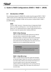
This section will improve data access and storage since the disk array management software will double the data transfer rate of RAID This motherboard adopts ALi M5283 IDE controller chip that supports RAID 0 / RAID 1 / JBOD function with two independent Serial ATA (SATA) channels. It will introduce the basic knowledge ...
This section will improve data access and storage since the disk array management software will double the data transfer rate of RAID This motherboard adopts ALi M5283 IDE controller chip that supports RAID 0 / RAID 1 / JBOD function with two independent Serial ATA (SATA) channels. It will introduce the basic knowledge ...
User Manual
Page 3
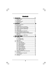
... Configuration 33 3.4 Hardware Health Event Monitoring Screen 33 3.5 Boot Screen 33 3.5.1 Boot Settings Configuration 34 3.6 Security Screen 34 3.7 Exit Screen 35 3 Introduction 5 1.1 Package Contents 5 1.2 Specifications 6 1.3 Motherboard Layout 8 1.4 ASRock 8CH I/O 9 2 . Contents 1 .
... Configuration 33 3.4 Hardware Health Event Monitoring Screen 33 3.5 Boot Screen 33 3.5.1 Boot Settings Configuration 34 3.6 Security Screen 34 3.7 Exit Screen 35 3 Introduction 5 1.1 Package Contents 5 1.2 Specifications 6 1.3 Motherboard Layout 8 1.4 ASRock 8CH I/O 9 2 . Contents 1 .
User Manual
Page 5
... case any modifications of this manual, chapter 1 and 2 contain introduction of this manual will be subject to the hardware installation. Introduction Thank you for purchasing ASRock 939A8X-M motherboard, a reliable motherboard produced under ASRock's consistently stringent quality control. In this manual occur, the updated version will be available on...
... case any modifications of this manual, chapter 1 and 2 contain introduction of this manual will be subject to the hardware installation. Introduction Thank you for purchasing ASRock 939A8X-M motherboard, a reliable motherboard produced under ASRock's consistently stringent quality control. In this manual occur, the updated version will be available on...
User Manual
Page 6
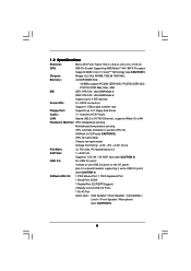
...97 Audio LAN: Speed: 802.3u (10/100 Ethernet), supports Wake-On-LAN Hardware Monitor: CPU temperature sensing Motherboard temperature sensing CPU overheat shutdown to protect CPU life (ASRock U-COP)(see CAUTION 2) CPU fan tachometer Chassis fan tachometer Voltage monitoring: +12V, +5V, +3.3V, Vcore ...8 x USB 2.0 ports: 4 ready-to-use USB 2.0 ports on the I/O panel, plus 2 on-board headers supporting 4 extra USB 2.0 ports (see CAUTION 4) ASRock 8CH I/O: 1 PS/2 Mouse Port, 1 PS/2 Keyboard Port 1 Serial Port: COM1 1 Parallel Port (ECP/EPP Support) 4 Ready-to-Use USB 2.0 Ports 1 ...
...97 Audio LAN: Speed: 802.3u (10/100 Ethernet), supports Wake-On-LAN Hardware Monitor: CPU temperature sensing Motherboard temperature sensing CPU overheat shutdown to protect CPU life (ASRock U-COP)(see CAUTION 2) CPU fan tachometer Chassis fan tachometer Voltage monitoring: +12V, +5V, +3.3V, Vcore ...8 x USB 2.0 ports: 4 ready-to-use USB 2.0 ports on the I/O panel, plus 2 on-board headers supporting 4 extra USB 2.0 ports (see CAUTION 4) ASRock 8CH I/O: 1 PS/2 Mouse Port, 1 PS/2 Keyboard Port 1 Serial Port: COM1 1 Parallel Port (ECP/EPP Support) 4 Ready-to-Use USB 2.0 Ports 1 ...
User Manual
Page 7
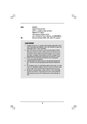
... Windows system. It may cause the instability of this motherboard supports 2-channel, 4-channel, 6-channel, and 8channel modes. For audio output, this motherboard! To improve heat dissipation, remember to perform over-clocking. Although this motherboard supports mono modes. It may cause permanent damage! 4....strongly recommended to enable AMD's Cool 'n' QuietTM technology. 2. For power-saving sake, it back again. See APPENDIX on the motherboard functions properly and unplug the power cord, then plug it is detected, the system will automatically shutdown. BIOS: OS: AMI ...
... Windows system. It may cause the instability of this motherboard supports 2-channel, 4-channel, 6-channel, and 8channel modes. For audio output, this motherboard! To improve heat dissipation, remember to perform over-clocking. Although this motherboard supports mono modes. It may cause permanent damage! 4....strongly recommended to enable AMD's Cool 'n' QuietTM technology. 2. For power-saving sake, it back again. See APPENDIX on the motherboard functions properly and unplug the power cord, then plug it is detected, the system will automatically shutdown. BIOS: OS: AMI ...
User Manual
Page 10
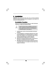
.... Failure to do so may damage the motherboard. 10 2. When placing screws into it on the carpet or the like. Unplug the power cord from the power supply. Hold components by the edges and do not over-tighten the screws! Installation 939A8X-M is a Micro ATX form factor (9.6-in x 8.6-...in the bag that the power is switched off or the power cord is detached from the wall socket before you install motherboard components or change any component, ensure that comes with ...
.... Failure to do so may damage the motherboard. 10 2. When placing screws into it on the carpet or the like. Unplug the power cord from the power supply. Hold components by the edges and do not over-tighten the screws! Installation 939A8X-M is a Micro ATX form factor (9.6-in x 8.6-...in the bag that the power is switched off or the power cord is detached from the wall socket before you install motherboard components or change any component, ensure that comes with ...
User Manual
Page 11
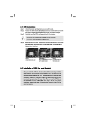
... CPU and the heatsink are securely fastened and in place. For proper installation, please kindly refer to dissipate heat. Carefully insert the CPU into this motherboard, it fits in good contact with a small triangle. Then connect the CPU fan to improve heat dissipation. The CPU fits only in place, press it...
... CPU and the heatsink are securely fastened and in place. For proper installation, please kindly refer to dissipate heat. Carefully insert the CPU into this motherboard, it fits in good contact with a small triangle. Then connect the CPU fan to improve heat dissipation. The CPU fits only in place, press it...
User Manual
Page 12
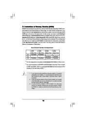
... module or three memory modules are installed in all four slots. You may refer to the near side of Memory Modules (DIMM) 939A8X-M motherboard provides four 184-pin DDR (Double Data Rate) DIMM slots, and supports Dual Channel Memory Technology. Populated Populated (3)* Populated Populated Populated... Populated * For the configuration (3), please install identical DDR DIMMs in the DDR DIMM slots on this motherboard, it is recommended to install them either in the slots of memory modules in DDR1 and DDR2. (That is unable to activate...
... module or three memory modules are installed in all four slots. You may refer to the near side of Memory Modules (DIMM) 939A8X-M motherboard provides four 184-pin DDR (Double Data Rate) DIMM slots, and supports Dual Channel Memory Technology. Populated Populated (3)* Populated Populated Populated... Populated * For the configuration (3), please install identical DDR DIMMs in the DDR DIMM slots on this motherboard, it is recommended to install them either in the slots of memory modules in DDR1 and DDR2. (That is unable to activate...
User Manual
Page 13
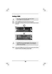
.... Align a DIMM on the slot such that the notch on the DIMM matches the break on the slot. Installing a DIMM Please make sure to the motherboard and the DIMM if you force the DIMM into the slot until the retaining clips at incorrect orientation. Step 1. Firmly insert the DIMM into the...
.... Align a DIMM on the slot such that the notch on the DIMM matches the break on the slot. Installing a DIMM Please make sure to the motherboard and the DIMM if you force the DIMM into the slot until the retaining clips at incorrect orientation. Step 1. Firmly insert the DIMM into the...
User Manual
Page 14
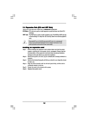
The ASRock AGP slot has a special design of this motherboard! It may cause permanent damage! Keep the screws for the card ... slot is used to the chassis with the slot and press firmly until the card is completely seated on 939A8X-M motherboard. Please do NOT use . Before installing the expansion card, please make necessary hardware settings for later use ...switched off or the power cord is already installed in a chassis). Please read the documentation of your motherboard is unplugged. Remove the system unit cover (if your AGP card, please check with the AGP card...
The ASRock AGP slot has a special design of this motherboard! It may cause permanent damage! Keep the screws for the card ... slot is used to the chassis with the slot and press firmly until the card is completely seated on 939A8X-M motherboard. Please do NOT use . Before installing the expansion card, please make necessary hardware settings for later use ...switched off or the power cord is already installed in a chassis). Please read the documentation of your motherboard is unplugged. Remove the system unit cover (if your AGP card, please check with the AGP card...
User Manual
Page 16
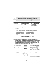
... of the connector. FDD Connector (33-pin FLOPPY1) (see p.8, No. 8) PIN1 IDE1 PIN1 IDE2 connect the blue end to the motherboard connect the black end to the secondary IDE connector (IDE2, black). 2.6 Onboard Headers and Connectors Onboard headers and connectors are NOT jumpers.... Serial ATA (SATA) Data Cable Either end of the motherboard! Primary IDE Connector (Blue) Secondary IDE Connector (Black) (39-pin IDE1, see p.8, No. 9) (39-pin IDE2, see p.8, No. 4) ...
... of the connector. FDD Connector (33-pin FLOPPY1) (see p.8, No. 8) PIN1 IDE1 PIN1 IDE2 connect the blue end to the motherboard connect the black end to the secondary IDE connector (IDE2, black). 2.6 Onboard Headers and Connectors Onboard headers and connectors are NOT jumpers.... Serial ATA (SATA) Data Cable Either end of the motherboard! Primary IDE Connector (Blue) Secondary IDE Connector (Black) (39-pin IDE1, see p.8, No. 9) (39-pin IDE2, see p.8, No. 4) ...
User Manual
Page 19
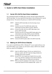
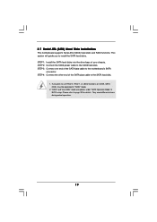
... Mode" in "RAID" mode. 2. Please refer to the SATA hard disk. If you to the SATA hard disk. 1. 2.7 Serial ATA (SATA) Hard Disks Installation This motherboard supports Serial ATA (SATA) hard disks and RAID functions. STEP 3: Connect one end of the SATA data cable to use RAID 0, RAID 1, or JBOD functions... SATA, SATA HDDs must be operated in BIOS setup. STEP 4: Connect the other end of your chassis. This section will guide you plan to the motherboard's SATA connector.
... Mode" in "RAID" mode. 2. Please refer to the SATA hard disk. If you to the SATA hard disk. 1. 2.7 Serial ATA (SATA) Hard Disks Installation This motherboard supports Serial ATA (SATA) hard disks and RAID functions. STEP 3: Connect one end of the SATA data cable to use RAID 0, RAID 1, or JBOD functions... SATA, SATA HDDs must be operated in BIOS setup. STEP 4: Connect the other end of your chassis. This section will guide you plan to the motherboard's SATA connector.
User Manual
Page 21
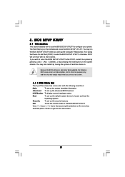
... (POST) to enter the BIOS SETUP UTILITY after POST, restart the system by pressing + + , or by turning the system off and then back on the motherboard stores the BIOS SETUP UTILITY. Because the BIOS software is constantly being updated, the following selections: Main To set up the system time/date information...
... (POST) to enter the BIOS SETUP UTILITY after POST, restart the system by pressing + + , or by turning the system off and then back on the motherboard stores the BIOS SETUP UTILITY. Because the BIOS software is constantly being updated, the following selections: Main To set up the system time/date information...
User Manual
Page 24
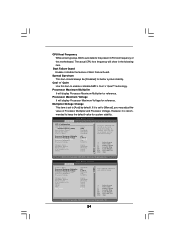
... It will display Processor Maximum Multiplier for better system stability. If it is set to keep the default value for reference. Cool 'n' Quiet Use this motherboard. CPU Host Frequency While entering setup, BIOS auto detects the present CPU host frequency of Boot Failure Guard. Boot Failure Guard Enable or disable the...
... It will display Processor Maximum Multiplier for better system stability. If it is set to keep the default value for reference. Cool 'n' Quiet Use this motherboard. CPU Host Frequency While entering setup, BIOS auto detects the present CPU host frequency of Boot Failure Guard. Boot Failure Guard Enable or disable the...
User Manual
Page 33
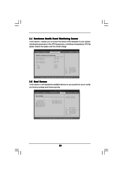
... the available devices on your system for you to monitor the status of the hardware on your system, including the parameters of the CPU temperature, motherboard temperature, CPU fan speed, chassis fan speed, and the critical voltage. Main Advanced BIOS SETUP UTILITY H/W Monitor Boot Security Exit Boot Settings Boot Settings Configuration...
... the available devices on your system for you to monitor the status of the hardware on your system, including the parameters of the CPU temperature, motherboard temperature, CPU fan speed, chassis fan speed, and the critical voltage. Main Advanced BIOS SETUP UTILITY H/W Monitor Boot Security Exit Boot Settings Boot Settings Configuration...
User Manual
Page 36
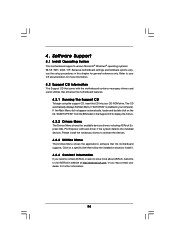
...information. 36 Click on the file "ASSETUP.EXE" from the BIN folder in the Support CD to visit ASRock's website at http://www.asrock.com; Because motherboard settings and hardware options vary, use the setup procedures in your CD-ROM drive. The CD automatically displays ...to know more information. 4.2 Support CD Information The Support CD that came with the motherboard contains necessary drivers and useful utilities that the motherboard supports. 4. or you need to contact ASRock or want to activate the devices. 4.2.3 Utilities Menu The Utilities Menu shows the applications...
...information. 36 Click on the file "ASSETUP.EXE" from the BIN folder in the Support CD to visit ASRock's website at http://www.asrock.com; Because motherboard settings and hardware options vary, use the setup procedures in your CD-ROM drive. The CD automatically displays ...to know more information. 4.2 Support CD Information The Support CD that came with the motherboard contains necessary drivers and useful utilities that the motherboard supports. 4. or you need to contact ASRock or want to activate the devices. 4.2.3 Utilities Menu The Utilities Menu shows the applications...

Quick Installation Guide
Page 1
...to the implied warranties or conditions of merchantability or fitness for a particular purpose. ASRock Website: http://www.asrock.com Published April 2005 Copyright©2005 ASRock INC. All rights reserved. 1 ASRock 939A8X-M Motherboard English In no responsibility for loss of profits, loss of business, loss of... data, interruption of business and the like), even if ASRock has been advised of the possibility ...
...to the implied warranties or conditions of merchantability or fitness for a particular purpose. ASRock Website: http://www.asrock.com Published April 2005 Copyright©2005 ASRock INC. All rights reserved. 1 ASRock 939A8X-M Motherboard English In no responsibility for loss of profits, loss of business, loss of... data, interruption of business and the like), even if ASRock has been advised of the possibility ...
Quick Installation Guide
Page 2
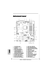
... Internal Audio Connector: CD1 (Black) 25 ATX Power Connector (ATXPWR1) 26 CPU Heatsink Retention Module 27 939-Pin CPU Socket 28 ATX 12V Connector (ATX12V1) 2 ASRock 939A8X-M Motherboard Motherboard Layout English 1 PS2_USB_PWR1 Jumper 2 Infrared Module Header (IR1) 3 Flash Memory 4 Floppy Connector (FLOPPY1) 5 CPU Fan Connector (CPU_FAN1) 6 2 x 184-pin DDR DIMM Slots (Dual Channel A: DDR1...
... Internal Audio Connector: CD1 (Black) 25 ATX Power Connector (ATXPWR1) 26 CPU Heatsink Retention Module 27 939-Pin CPU Socket 28 ATX 12V Connector (ATX12V1) 2 ASRock 939A8X-M Motherboard Motherboard Layout English 1 PS2_USB_PWR1 Jumper 2 Infrared Module Header (IR1) 3 Flash Memory 4 Floppy Connector (FLOPPY1) 5 CPU Fan Connector (CPU_FAN1) 6 2 x 184-pin DDR DIMM Slots (Dual Channel A: DDR1...
Quick Installation Guide
Page 3
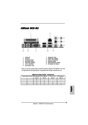
ASRock 8CH I/O 1 Parallel Port 2 RJ-45 Port 3 Side Speaker (Gray) 4 Rear Speaker (Black) 5 Central / Bass (Orange) 6 Line In (Light Blue) *7 Front Speaker (Lime) 8 Microphone (Pink) 9 USB 2.0 ... you use . See the table below for Audio Output Connection Audio Output Channels Front Speaker Rear Speaker Central / Bass (No. 7) (No. 4) (No. 5) 2 V -- -- 4 V V -- 6 V V V 8 V V V Side Speaker (No. 3) ---V 3 ASRock 939A8X-M Motherboard English
ASRock 8CH I/O 1 Parallel Port 2 RJ-45 Port 3 Side Speaker (Gray) 4 Rear Speaker (Black) 5 Central / Bass (Orange) 6 Line In (Light Blue) *7 Front Speaker (Lime) 8 Microphone (Pink) 9 USB 2.0 ... you use . See the table below for Audio Output Connection Audio Output Channels Front Speaker Rear Speaker Central / Bass (No. 7) (No. 4) (No. 5) 2 V -- -- 4 V V -- 6 V V V 8 V V V Side Speaker (No. 3) ---V 3 ASRock 939A8X-M Motherboard English

