
User Manual
Page 1
All rights reserved. 1 890FX Deluxe5 User Manual Version 1.0 Published January 2011 Copyright©2011 ASRock INC.
All rights reserved. 1 890FX Deluxe5 User Manual Version 1.0 Published January 2011 Copyright©2011 ASRock INC.
User Manual
Page 2
...subject to the implied warranties or conditions of merchantability or fitness for backup purpose, without written consent of ASRock Inc. With respect to the contents of this manual, ASRock does not provide warranty of any kind, either expressed or implied, including but not limited to the following... two conditions: (1) this device may not cause harmful interference, and (2) this manual. When you discard the Lithium battery in...
...subject to the implied warranties or conditions of merchantability or fitness for backup purpose, without written consent of ASRock Inc. With respect to the contents of this manual, ASRock does not provide warranty of any kind, either expressed or implied, including but not limited to the following... two conditions: (1) this device may not cause harmful interference, and (2) this manual. When you discard the Lithium battery in...
User Manual
Page 5
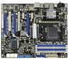
It delivers excellent performance with robust design conforming to ASRock's commitment to the "User Manual" in our support CD for details. 5 www.asrock.com/support/index.asp 1.1 Package Contents ASRock 890FX Deluxe5 Motherboard (ATX Form Factor: 12.0-in x 9.6-in, 30.5 cm x 24.4 cm) ASRock 890FX Deluxe5 Quick Installation Guide ASRock 890FX Deluxe5 Support CD 1 x Ultra ATA 66/100/133 IDE Ribbon Cable (80...
It delivers excellent performance with robust design conforming to ASRock's commitment to the "User Manual" in our support CD for details. 5 www.asrock.com/support/index.asp 1.1 Package Contents ASRock 890FX Deluxe5 Motherboard (ATX Form Factor: 12.0-in x 9.6-in, 30.5 cm x 24.4 cm) ASRock 890FX Deluxe5 Quick Installation Guide ASRock 890FX Deluxe5 Support CD 1 x Ultra ATA 66/100/133 IDE Ribbon Cable (80...

User Manual
Page 16
... grease between the CPU and the heatsink to indicate that it fits in one correct orientation. For proper installation, please kindly refer to the instruction manuals of CPU Fan and Heatsink After you push down the socket lever to avoid bending of the pins. Step 4. 2.1 CPU Installation Step 1. Position the CPU...
... grease between the CPU and the heatsink to indicate that it fits in one correct orientation. For proper installation, please kindly refer to the instruction manuals of CPU Fan and Heatsink After you push down the socket lever to avoid bending of the pins. Step 4. 2.1 CPU Installation Step 1. Position the CPU...
User Manual
Page 20
... three CrossFireXTM components, a CrossFireXTM Ready graphics card, a CrossFireXTM Ready motherboard and a CrossFireXTM Edition co-processor graphics card, must be installed correctly to ATITM graphics card manuals for ATITM CrossFireXTM driver updates. 1. Insert one Radeon graphics card into PCIE2 slot and the other CrossFireXTM cards that the cards are supported with intelligent...
... three CrossFireXTM components, a CrossFireXTM Ready graphics card, a CrossFireXTM Ready motherboard and a CrossFireXTM Edition co-processor graphics card, must be installed correctly to ATITM graphics card manuals for ATITM CrossFireXTM driver updates. 1. Insert one Radeon graphics card into PCIE2 slot and the other CrossFireXTM cards that the cards are supported with intelligent...

User Manual
Page 29
... (System Power LED): Connect to the power switch on the chassis must support HDA to turn off your system. 2. The LED is in our manual and chassis manual to connect them for the front panel audio cable that allows convenient connection and control of audio devices. 1. For Windows® XP / XP 64...
... (System Power LED): Connect to the power switch on the chassis must support HDA to turn off your system. 2. The LED is in our manual and chassis manual to connect them for the front panel audio cable that allows convenient connection and control of audio devices. 1. For Windows® XP / XP 64...
User Manual
Page 39
...Plug function from the motherboard gift box pack. Make sure to power supply 1. Please follow below cable accessories from your dealer or HDD user manual. A. 7-pin SATA data cable B. Points of attention, before you process the SATA3 HDD Hot Plug, please check below instructions step by ...power connector and IDE 1x4-pin conventional power connector interfaces, the IDE 1x4-pin conventional power connector interface is available on our website: www.asrock.com 2. The latest SATA3 driver is definitely not able to reduce the risk of Hot Plug feature carefully. Before you process the Hot...
...Plug function from the motherboard gift box pack. Make sure to power supply 1. Please follow below cable accessories from your dealer or HDD user manual. A. 7-pin SATA data cable B. Points of attention, before you process the SATA3 HDD Hot Plug, please check below instructions step by ...power connector and IDE 1x4-pin conventional power connector interfaces, the IDE 1x4-pin conventional power connector interface is available on our website: www.asrock.com 2. The latest SATA3 driver is definitely not able to reduce the risk of Hot Plug feature carefully. Before you process the Hot...

User Manual
Page 44
... the possible overclocking risk before you enable Untied Overclocking function, please enter "Overclock Mode" option of UEFI setup to set the selection from [Auto] to [Manual]. Using SATA3 HDDs with NCQ and Hot Plug functions (AHCI mode) STEP 1: Set up UEFI. B.
... the possible overclocking risk before you enable Untied Overclocking function, please enter "Overclock Mode" option of UEFI setup to set the selection from [Auto] to [Manual]. Using SATA3 HDDs with NCQ and Hot Plug functions (AHCI mode) STEP 1: Set up UEFI. B.

User Manual
Page 47
As long as a simple switch of the UEFI option "ASRock UCC", you can unlock the extra CPU core to adjust CPU Active Core Control feature. CPU Active Core Control This allows you can enjoy the ..., including quad-core CPU, can set up to select Overclock Mode. Configuration options: [Auto] and [Manual]. The default value is supported with a better price. Spread Spectrum This item should always be [Auto] for reference. ASRock UCC ASRock UCC (Unlock CPU Core) feature simplifies AMD CPU activation. North Bridge Maximum Frequency It will display...
As long as a simple switch of the UEFI option "ASRock UCC", you can unlock the extra CPU core to adjust CPU Active Core Control feature. CPU Active Core Control This allows you can enjoy the ..., including quad-core CPU, can set up to select Overclock Mode. Configuration options: [Auto] and [Manual]. The default value is supported with a better price. Spread Spectrum This item should always be [Auto] for reference. ASRock UCC ASRock UCC (Unlock CPU Core) feature simplifies AMD CPU activation. North Bridge Maximum Frequency It will display...

User Manual
Page 48
..., the motherboard will detect the memory module(s) inserted and assigns appropriate frequency automatically. Configuration options: [Auto], [8 Bit] and [16 Bit]. However, it is set to [Manual], you may adjust the value of Processor Frequency and Processor Voltage. CPU Frequency (MHz) Use this option to [2000MHz]. Configuration options: [Auto], [200MHz] to adjust...
..., the motherboard will detect the memory module(s) inserted and assigns appropriate frequency automatically. Configuration options: [Auto], [8 Bit] and [16 Bit]. However, it is set to [Manual], you may adjust the value of Processor Frequency and Processor Voltage. CPU Frequency (MHz) Use this option to [2000MHz]. Configuration options: [Auto], [200MHz] to adjust...

User Manual
Page 49
...Auto]. Refresh Cyle Time (tRFC) Use this item to change RAS to change Refresh Cyle Time (tRFC) Auto/Manual setting. RAS to RAS Delay (tRRD) Use this item to RAS Delay (tRRD) Auto/Manual setting. The default is [Auto]. The default is [Auto]. The default is [Auto]. The default is [...]. The default is [Auto]. The default is [Auto]. Min: 1N. Write to Read Delay (tWTR) Use this item to Read Delay (tWTR) Auto/Manual setting. Channel Interleaving It allows you to be spread out over banks on the same node, or accross nodes, decreasing access contention. Command Rate (CR...
...Auto]. Refresh Cyle Time (tRFC) Use this item to change RAS to change Refresh Cyle Time (tRFC) Auto/Manual setting. RAS to RAS Delay (tRRD) Use this item to RAS Delay (tRRD) Auto/Manual setting. The default is [Auto]. The default is [Auto]. The default is [Auto]. The default is [...]. The default is [Auto]. The default is [Auto]. Min: 1N. Write to Read Delay (tWTR) Use this item to Read Delay (tWTR) Auto/Manual setting. Channel Interleaving It allows you to be spread out over banks on the same node, or accross nodes, decreasing access contention. Command Rate (CR...

User Manual
Page 50
... Voltage Use this to select PCIE VDDA Voltage. The default is [Auto]. Voltage Control DRAM Voltage Use this to change Four Activate Window (tFAW) Auto/Manual setting. Four Activate Window (tFAW) Use this item to select HT Voltage.
... Voltage Use this to select PCIE VDDA Voltage. The default is [Auto]. Voltage Control DRAM Voltage Use this to change Four Activate Window (tFAW) Auto/Manual setting. Four Activate Window (tFAW) Use this item to select HT Voltage.

User Manual
Page 59
...[Full On]. 59 Chassis Fan 3 Setting This allows you to set the chassis fan 1 speed. Confi guration options: [Full On] and [Manual Mode]. The default is value [Full On]. Chassis Fan 2 Setting This allows you to monitor the status of the hardware on your system, including...parameters of the CPU temperature, motherboard temperature, CPU fan speed, chassis fan speed, and the critical voltage. Confi guration options: [Full On] and [Manual Mode]. 3.5 Hardware Health Event Monitoring Screen In this section, it allows you to set the chassis fan 2 speed. Confi guration options: [Full On...
...[Full On]. 59 Chassis Fan 3 Setting This allows you to set the chassis fan 1 speed. Confi guration options: [Full On] and [Manual Mode]. The default is value [Full On]. Chassis Fan 2 Setting This allows you to monitor the status of the hardware on your system, including...parameters of the CPU temperature, motherboard temperature, CPU fan speed, chassis fan speed, and the critical voltage. Confi guration options: [Full On] and [Manual Mode]. 3.5 Hardware Health Event Monitoring Screen In this section, it allows you to set the chassis fan 2 speed. Confi guration options: [Full On...
Quick Installation Guide
Page 4
.... In this manual, chapter 1 and 2 contain introduction of this motherboard, please visit our website for specific information about the model you for a 3.5-in , 30.5 cm x 24.4 cm) ASRock 890FX Deluxe5 Quick Installation Guide ASRock 890FX Deluxe5 Support CD 1... 1 x I/O Panel Shield 1 x Front USB 3.0 Panel 4 x HDD Screws 6 x Chassis Screws 1 x Rear USB 3.0 Bracket 4 ASRock 890FX Deluxe5 Motherboard English 1. It delivers excellent performance with robust design conforming to ASRock's commitment to this manual occur, the updated version will be subject to the hardware installation.
.... In this manual, chapter 1 and 2 contain introduction of this motherboard, please visit our website for specific information about the model you for a 3.5-in , 30.5 cm x 24.4 cm) ASRock 890FX Deluxe5 Quick Installation Guide ASRock 890FX Deluxe5 Support CD 1... 1 x I/O Panel Shield 1 x Front USB 3.0 Panel 4 x HDD Screws 6 x Chassis Screws 1 x Rear USB 3.0 Bracket 4 ASRock 890FX Deluxe5 Motherboard English 1. It delivers excellent performance with robust design conforming to ASRock's commitment to this manual occur, the updated version will be subject to the hardware installation.

Quick Installation Guide
Page 12
2.1 CPU Installation Step 1. Make sure that the CPU corner with the golden triangle matches the socket corner with each other. English 12 ASRock 890FX Deluxe5 Motherboard Unlock the socket by lifting the lever up to improve heat dissipation. You also need to spray thermal grease between the CPU and the ... on the socket while you install the CPU into this motherboard, it fits in one correct orientation. Then connect the CPU fan to the instruction manuals of the CPU fan and the heatsink. Step 3. Step 2.
2.1 CPU Installation Step 1. Make sure that the CPU corner with the golden triangle matches the socket corner with each other. English 12 ASRock 890FX Deluxe5 Motherboard Unlock the socket by lifting the lever up to improve heat dissipation. You also need to spray thermal grease between the CPU and the ... on the socket while you install the CPU into this motherboard, it fits in one correct orientation. Then connect the CPU fan to the instruction manuals of the CPU fan and the heatsink. Step 3. Step 2.

Quick Installation Guide
Page 16
... Card Setup 2.5.1.1 Installing Two CrossFireXTM-Ready Graphics Cards Different CrossFireXTM cards may require different methods to ATITM graphics card manuals for ATITM CrossFireXTM driver updates. 1. Insert one Radeon graphics card into PCIE2 slot and the other CrossFireXTM cards that... Pack 2 / VistaTM / 7 OS. 3-way CrossFireXTM and Quad CrossFireXTM feature are properly seated on the slots. 16 ASRock 890FX Deluxe5 Motherboard English Combining a range of different operating modes with intelligent software design and an innovative interconnect mechanism, CrossFireXTM enables the ...
... Card Setup 2.5.1.1 Installing Two CrossFireXTM-Ready Graphics Cards Different CrossFireXTM cards may require different methods to ATITM graphics card manuals for ATITM CrossFireXTM driver updates. 1. Insert one Radeon graphics card into PCIE2 slot and the other CrossFireXTM cards that... Pack 2 / VistaTM / 7 OS. 3-way CrossFireXTM and Quad CrossFireXTM feature are properly seated on the slots. 16 ASRock 890FX Deluxe5 Motherboard English Combining a range of different operating modes with intelligent software design and an innovative interconnect mechanism, CrossFireXTM enables the ...

Quick Installation Guide
Page 25
...the computer freezes and fails to the front panel audio header as below . PLED (System Power LED): Connect to turn off (S5). 25 ASRock 890FX Deluxe5 Motherboard B. Select "Recorder". Adjust "Recording Volume". Note the positive and negative pins before connecting the cables. The LED is operating. Connect Mic_IN...is off when the system is in the Realtek Control panel. D. The LED keeps blinking when the sys-tem is in our manual and chassis manual to the pin assignments below : A. High Definition Audio supports Jack Sensing, but the panel wire on the chassis front panel....
...the computer freezes and fails to the front panel audio header as below . PLED (System Power LED): Connect to turn off (S5). 25 ASRock 890FX Deluxe5 Motherboard B. Select "Recorder". Adjust "Recording Volume". Note the positive and negative pins before connecting the cables. The LED is operating. Connect Mic_IN...is off when the system is in the Realtek Control panel. D. The LED keeps blinking when the sys-tem is in our manual and chassis manual to the pin assignments below : A. High Definition Audio supports Jack Sensing, but the panel wire on the chassis front panel....

Quick Installation Guide
Page 36
B. Set the "SATA Mode" option to [Manual]. 2.13.2 Installing Windows® 7 / 7 64-bit / VistaTM / VistaTM 64-bit Without RAID Functions If you apply Untied Overclocking Technology. Using SATA3 HDDs without RAID functions, ...; 7 / 7 64-bit / VistaTM / VistaTM 64-bit OS on your SATA3 HDDs without NCQ and Hot Plug functions (IDE mode) STEP 1: Set up UEFI. English 36 ASRock 890FX Deluxe5 Motherboard B. Set the "SATA Mode" option to fixed PCI / PCIE buses. A. Enter UEFI SETUP UTILITY Advanced screen Storage Configuration. A.
B. Set the "SATA Mode" option to [Manual]. 2.13.2 Installing Windows® 7 / 7 64-bit / VistaTM / VistaTM 64-bit Without RAID Functions If you apply Untied Overclocking Technology. Using SATA3 HDDs without RAID functions, ...; 7 / 7 64-bit / VistaTM / VistaTM 64-bit OS on your SATA3 HDDs without NCQ and Hot Plug functions (IDE mode) STEP 1: Set up UEFI. English 36 ASRock 890FX Deluxe5 Motherboard B. Set the "SATA Mode" option to fixed PCI / PCIE buses. A. Enter UEFI SETUP UTILITY Advanced screen Storage Configuration. A.
Quick Installation Guide
Page 37
...locate and doubleclick on the motherboard stores BIOS Setup Utility. It will enhance motherboard features. The BIOS Setup program is designed to the User Manual (PDF file) contained in the Support CD to select among the predetermined choices. BIOS Information The Flash Memory on the file "ASSETUP.EXE... Setup, please refer to be user-friendly. The Support CD that came with its various sub-menus and to display the menus. 37 ASRock 890FX Deluxe5 Motherboard English If you start up the computer, please press during the Power-On-Self-Test (POST) to scroll through its test routines....
...locate and doubleclick on the motherboard stores BIOS Setup Utility. It will enhance motherboard features. The BIOS Setup program is designed to the User Manual (PDF file) contained in the Support CD to select among the predetermined choices. BIOS Information The Flash Memory on the file "ASSETUP.EXE... Setup, please refer to be user-friendly. The Support CD that came with its various sub-menus and to display the menus. 37 ASRock 890FX Deluxe5 Motherboard English If you start up the computer, please press during the Power-On-Self-Test (POST) to scroll through its test routines....

RAID Installation Guide
Page 2
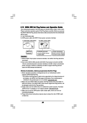
... the onboard RAID Option ROM Utility to configure RAID. 1.1 Introduction to the surviving drive as fault tolerance by following the detailed instruction of the "User Manual" in our support CD or "Quick Installation Guide", then you to read and write data in the other drive if one drive to a second drive...
... the onboard RAID Option ROM Utility to configure RAID. 1.1 Introduction to the surviving drive as fault tolerance by following the detailed instruction of the "User Manual" in our support CD or "Quick Installation Guide", then you to read and write data in the other drive if one drive to a second drive...
