
User Manual
Page 4
... 37 3.1 Introduction 37 3.1.1 BIOS Menu Bar 37 3.1.2 Navigation Keys 38 3.2 Main Screen 38 3.3 OC Tweaker Screen 39 3.4 Advanced Screen 46 3.4.1 CPU Configuration 47 3.4.2 Chipset Configuration 48 3.4.3 ACPI Configuration 50 3.4.4 ...
... 37 3.1 Introduction 37 3.1.1 BIOS Menu Bar 37 3.1.2 Navigation Keys 38 3.2 Main Screen 38 3.3 OC Tweaker Screen 39 3.4 Advanced Screen 46 3.4.1 CPU Configuration 47 3.4.2 Chipset Configuration 48 3.4.3 ACPI Configuration 50 3.4.4 ...

User Manual
Page 5
... to change without further notice. Because the motherboard specifications and the BIOS software might be updated, the content of this motherboard, please visit our website for specific information about the model you for purchasing ASRock 880GMH-LE/USB3 motherboard, a reliable motherboard produced under ASRock's consistently stringent quality control. 1. You may find the latest VGA cards and...
... to change without further notice. Because the motherboard specifications and the BIOS software might be updated, the content of this motherboard, please visit our website for specific information about the model you for purchasing ASRock 880GMH-LE/USB3 motherboard, a reliable motherboard produced under ASRock's consistently stringent quality control. 1. You may find the latest VGA cards and...

User Manual
Page 7
... header - 1 x Print port header - 1 x COM port header - Realtek RTL8111E - VCCM, NB Voltage Multi-adjustment - Front panel audio connector - 3 x USB 2.0 headers (support 6 USB 2.0 ports) - 8Mb AMI BIOS - Explorer, AMD Fusion, ASRock Software Suite (CyberLink DVD Suite - Trial) 7 CPU/Chassis/Power FAN connector - 24 pin ATX power connector - 4 pin 12V power connector - AMI Legal...
... header - 1 x Print port header - 1 x COM port header - Realtek RTL8111E - VCCM, NB Voltage Multi-adjustment - Front panel audio connector - 3 x USB 2.0 headers (support 6 USB 2.0 ports) - 8Mb AMI BIOS - Explorer, AMD Fusion, ASRock Software Suite (CyberLink DVD Suite - Trial) 7 CPU/Chassis/Power FAN connector - 24 pin ATX power connector - 4 pin 12V power connector - AMI Legal...

User Manual
Page 8
... even cause damage to the components and devices of your own risk and expense. ASRock U-COP (see CAUTION 13) * For detailed product information, please visit our website: http://www.asrock.com WARNING Please realize that there is required) (see CAUTION 12) - CPU/...3V, Vcore OS - ErP/EuP Ready (ErP/EuP ready power supply is a certain risk involved with overclocking, including adjusting the setting in the BIOS, applying Untied Overclocking Technology, or using the thirdparty overclocking tools. CPU Frequency Stepless Control (see CAUTION 10) - Instant Boot - Boot Failure Guard...
... even cause damage to the components and devices of your own risk and expense. ASRock U-COP (see CAUTION 13) * For detailed product information, please visit our website: http://www.asrock.com WARNING Please realize that there is required) (see CAUTION 12) - CPU/...3V, Vcore OS - ErP/EuP Ready (ErP/EuP ready power supply is a certain risk involved with overclocking, including adjusting the setting in the BIOS, applying Untied Overclocking Technology, or using the thirdparty overclocking tools. CPU Frequency Stepless Control (see CAUTION 10) - Instant Boot - Boot Failure Guard...

User Manual
Page 9
...to adjust your SATAII hard disk drive to SATAII mode. ASRock website http://www.asrock.com 4. The maximum shared memory size is defined by hardware monitor function and overclock your system by the chipset vendor and is a BIOS flash utility embedded in Flash ROM. Before installing SATAII hard...want to adopt DDR3 1800/1600 memory module on this tool and save the new BIOS file to access ASRock Instant Flash. It is no such limitation. 5. ASRock website: http://www.asrock.com 8. This convenient BIOS update tool allows you can also connect SATA hard disk to the operating system limitation...
...to adjust your SATAII hard disk drive to SATAII mode. ASRock website http://www.asrock.com 4. The maximum shared memory size is defined by hardware monitor function and overclock your system by the chipset vendor and is a BIOS flash utility embedded in Flash ROM. Before installing SATAII hard...want to adopt DDR3 1800/1600 memory module on this tool and save the new BIOS file to access ASRock Instant Flash. It is no such limitation. 5. ASRock website: http://www.asrock.com 8. This convenient BIOS update tool allows you can also connect SATA hard disk to the operating system limitation...
User Manual
Page 11
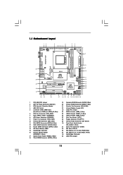
... Top: LINE IN Center: FRONT Bottom: MIC IN AMD 880G IDE1 Chipset LAN PCIE1 AUDIO CODEC Super I/O PCIE2 880GMH-LE/USB3 PCI1 1 HD_AUDIO1 1 COM1 CD1 FLOPPY1 PCI2 LPT1 1 SATAII_4 SATAII_5 SATAII_6 AMD SB710 Chipset RoHS 8Mb BIOS SPEAKER1 1 PANEL 1 PLED PWRBTN 1 HDLED RESET USB8_9 1 USB10_11 USB6_7 1 1 USB_PW3 1 SATAII_1 SATAII_2 SATAII_3 IR1 1 CHA_FAN1 30 29...
... Top: LINE IN Center: FRONT Bottom: MIC IN AMD 880G IDE1 Chipset LAN PCIE1 AUDIO CODEC Super I/O PCIE2 880GMH-LE/USB3 PCI1 1 HD_AUDIO1 1 COM1 CD1 FLOPPY1 PCI2 LPT1 1 SATAII_4 SATAII_5 SATAII_6 AMD SB710 Chipset RoHS 8Mb BIOS SPEAKER1 1 PANEL 1 PLED PWRBTN 1 HDLED RESET USB8_9 1 USB10_11 USB6_7 1 1 USB_PW3 1 SATAII_1 SATAII_2 SATAII_3 IR1 1 CHA_FAN1 30 29...

User Manual
Page 18
... corresponding connectors of "Share Memory", [Auto], will be designated as appropriate for the diaplay icon identified by the number 2. If you do not adjust the BIOS setup, the default value of the add-on PCI Express VGA card on VGA card is inserted to install them again. 5. For Windows® XP... cable to be Primary, and all additional monitors will disable VGA/D-Sub function when the add-on PCIE2 slot. 3. Click "Apply" or "OK" to enter BIOS setup. Install the onboard VGA driver and the add-on PCI Express VGA card driver to enable the function of the system memory.
... corresponding connectors of "Share Memory", [Auto], will be designated as appropriate for the diaplay icon identified by the number 2. If you do not adjust the BIOS setup, the default value of the add-on PCI Express VGA card on VGA card is inserted to install them again. 5. For Windows® XP... cable to be Primary, and all additional monitors will disable VGA/D-Sub function when the add-on PCIE2 slot. 3. Click "Apply" or "OK" to enter BIOS setup. Install the onboard VGA driver and the add-on PCI Express VGA card driver to enable the function of the system memory.

User Manual
Page 20
... system includes an ATITM RadeonTM 5450 series graphics processor and a motherboard based on your system for ATITM Hybrid CrossFireXTM. Connect the monitor cable to enter BIOS setup. Press to the correspondent connector on the PCI Express graphics card on PCIE2 slot. Then set the option "Surround View" to your Windows®...
... system includes an ATITM RadeonTM 5450 series graphics processor and a motherboard based on your system for ATITM Hybrid CrossFireXTM. Connect the monitor cable to enter BIOS setup. Press to the correspondent connector on the PCI Express graphics card on PCIE2 slot. Then set the option "Surround View" to your Windows®...

User Manual
Page 22
... pin2, pin3 to enable (see p.11, No. 23) 1_2 +5V 2_3 +5VSB Short pin2, pin3 to clear the CMOS when you just finish updating the BIOS, you select +5V_DUAL, USB devices can wake up events. When the jumper cap is placed on CLRCMOS1 for PS/2 or USB23 wake up the system...-CMOS action. 22 Jumper Setting PS2_USB_PW1 1_2 2_3 Short pin2, pin3 to enable (see p.11, No. 7) Default Clear CMOS Note: CLRCMOS1 allows you update the BIOS. To clear and reset the system parameters to +5V. Note: To select +5V_DUAL, it down before you do not clear the CMOS right after you...
... pin2, pin3 to enable (see p.11, No. 23) 1_2 +5V 2_3 +5VSB Short pin2, pin3 to clear the CMOS when you just finish updating the BIOS, you select +5V_DUAL, USB devices can wake up events. When the jumper cap is placed on CLRCMOS1 for PS/2 or USB23 wake up the system...-CMOS action. 22 Jumper Setting PS2_USB_PW1 1_2 2_3 Short pin2, pin3 to enable (see p.11, No. 7) Default Clear CMOS Note: CLRCMOS1 allows you update the BIOS. To clear and reset the system parameters to +5V. Note: To select +5V_DUAL, it down before you do not clear the CMOS right after you...

User Manual
Page 32
... CD driver page. Therefore, the drivers you install can be auto-detected and listed on the screen, "Generate Serial ATA driver diskette [YN]?", press . Enter BIOS SETUP UTILITY Advanced screen Storage Configuration. D. Then, the drivers compatible to your optical drive first. A. A. 2.13 Driver Installation Guide To install the drivers to ...174; XP / XP 64-bit With RAID Functions If you see these messages, Please insert a blank formatted diskette into the floppy diskette. 32 B. Insert the ASRock Support CD into the floppy drive, and press any key to [RAID].
... CD driver page. Therefore, the drivers you install can be auto-detected and listed on the screen, "Generate Serial ATA driver diskette [YN]?", press . Enter BIOS SETUP UTILITY Advanced screen Storage Configuration. D. Then, the drivers compatible to your optical drive first. A. A. 2.13 Driver Installation Guide To install the drivers to ...174; XP / XP 64-bit With RAID Functions If you see these messages, Please insert a blank formatted diskette into the floppy diskette. 32 B. Insert the ASRock Support CD into the floppy drive, and press any key to [RAID].

User Manual
Page 33
... driver. Select the driver to install according to [RAID]. A. Please refer to set RAID configuration. STEP 2: Use "RAID Installation Guide" to the BIOS RAID installation guide part of Windows® setup, press F6 to install Windows® XP / XP 64-bit OS on your system. 33 When... guide in the following path in the Support CD for proper configuration. After reading the floppy disk, the driver will be presented. Enter BIOS SETUP UTILITY Advanced screen Storage Configuration. If you install Windows® XP / XP 64-bit on IDE HDDs and want to manage (...
... driver. Select the driver to install according to [RAID]. A. Please refer to set RAID configuration. STEP 2: Use "RAID Installation Guide" to the BIOS RAID installation guide part of Windows® setup, press F6 to install Windows® XP / XP 64-bit OS on your system. 33 When... guide in the following path in the Support CD for proper configuration. After reading the floppy disk, the driver will be presented. Enter BIOS SETUP UTILITY Advanced screen Storage Configuration. If you install Windows® XP / XP 64-bit on IDE HDDs and want to manage (...

User Manual
Page 34
...in the Support CD: .. \ RAID Installation Guide NOTE2. Using SATA / SATAII HDDs with NCQ and Hot Plug functions (AHCI mode) STEP 1: Set Up BIOS. STEP 4: Install Windows® XP / XP 64-bit OS on your SATA / SATAII HDDs without RAID functions, please follow below steps. At the ...Controller-x86 platform" for Windows® XP, or "AMD AHCI Compatible RAID Controller-x64 platform" for Windows® XP 64-bit.) 34 Enter BIOS SETUP UTILITY Advanced screen Storage Configuration. You can start to install Windows® XP / XP 64-bit on your system. A. When prompted, ...
...in the Support CD: .. \ RAID Installation Guide NOTE2. Using SATA / SATAII HDDs with NCQ and Hot Plug functions (AHCI mode) STEP 1: Set Up BIOS. STEP 4: Install Windows® XP / XP 64-bit OS on your SATA / SATAII HDDs without RAID functions, please follow below steps. At the ...Controller-x86 platform" for Windows® XP, or "AMD AHCI Compatible RAID Controller-x64 platform" for Windows® XP 64-bit.) 34 Enter BIOS SETUP UTILITY Advanced screen Storage Configuration. You can start to install Windows® XP / XP 64-bit on your system. A. When prompted, ...

User Manual
Page 35
...-bit on your SATA / SATAII HDDs without RAID functions, please follow below steps. Set the "SATA Operation Mode" option to [AHCI]. B. B. Enter BIOS SETUP UTILITY Advanced screen Storage Configuration. A. B. Set the "SATA Operation Mode" option to [IDE]. STEP 2: Install Windows® 7 / 7 64...-bit / VistaTM / VistaTM 64-bit OS on your system. Enter BIOS SETUP UTILITY Advanced screen Storage Configuration. STEP 2: Install Windows® 7 / 7 64-bit / VistaTM / VistaTM 64-bit OS on your system. 35 ...
...-bit on your SATA / SATAII HDDs without RAID functions, please follow below steps. Set the "SATA Operation Mode" option to [AHCI]. B. B. Enter BIOS SETUP UTILITY Advanced screen Storage Configuration. A. B. Set the "SATA Operation Mode" option to [IDE]. STEP 2: Install Windows® 7 / 7 64...-bit / VistaTM / VistaTM 64-bit OS on your system. Enter BIOS SETUP UTILITY Advanced screen Storage Configuration. STEP 2: Install Windows® 7 / 7 64-bit / VistaTM / VistaTM 64-bit OS on your system. 35 ...

User Manual
Page 36
... environment. Please refer to the warning on page 8 for the possible overclocking risk before you enable Untied Overclocking function, please enter "Overclock Mode" option of BIOS setup to set the selection from [Auto] to fixed PCI / PCIE buses. Before you apply Untied Overclocking Technology. 36
... environment. Please refer to the warning on page 8 for the possible overclocking risk before you enable Untied Overclocking function, please enter "Overclock Mode" option of BIOS setup to set the selection from [Auto] to fixed PCI / PCIE buses. Before you apply Untied Overclocking Technology. 36

User Manual
Page 37
... and descriptions are for reference purpose only, and they may also restart by pressing the reset button on your system. Because the BIOS software is constantly being updated, the following selections: Main To set up the system time/date information OC Tweaker To set up overclocking... features Advanced To set up the advanced BIOS features H/W Monitor To display current hardware status Boot To set up the default system device to locate and load the Operating System Security To...
... and descriptions are for reference purpose only, and they may also restart by pressing the reset button on your system. Because the BIOS software is constantly being updated, the following selections: Main To set up the system time/date information OC Tweaker To set up overclocking... features Advanced To set up the advanced BIOS features H/W Monitor To display current hardware status Boot To set up the default system device to locate and load the Operating System Security To...

User Manual
Page 38
... UTILITY Main OC Tweaker Advanced H/W Monitor Boot Security Exit System Overview System Time System Date [17:00:09] [Mon 06/07/2010] BIOS Version : 880GMH-LE/USB3 P1.00 Processor Type : AMD Athlon(tm) II X4 960T Processor (64bit) Processor Speed : 3000MHz Microcode Update : 100FA0/10000BF L1 Cache Size : 512KB L2 Cache ... for the function description of each navigation key. 3.1.2 Navigation Keys Please check the following table for all the settings To save changes and exit the BIOS SETUP UTILITY To jump to the Exit Screen or exit the current screen 3.2 Main Screen When you enter the...
... UTILITY Main OC Tweaker Advanced H/W Monitor Boot Security Exit System Overview System Time System Date [17:00:09] [Mon 06/07/2010] BIOS Version : 880GMH-LE/USB3 P1.00 Processor Type : AMD Athlon(tm) II X4 960T Processor (64bit) Processor Speed : 3000MHz Microcode Update : 100FA0/10000BF L1 Cache Size : 512KB L2 Cache ... for the function description of each navigation key. 3.1.2 Navigation Keys Please check the following table for all the settings To save changes and exit the BIOS SETUP UTILITY To jump to the Exit Screen or exit the current screen 3.2 Main Screen When you enter the...

User Manual
Page 39
... Guard Count Enable or disable the feature of Boot Failure Guard. 3.3 OC Tweaker Screen In the OC Tweaker screen, you can set up overclocking features. BIOS SETUP UTILITY Main OC Tweaker Advanced H/W Monitor Boot Security Exit EZ Overclocking Load Optimized CPU OC Setting [Press Enter] Load Optimized mGPU OC Setting [Press...
... Guard Count Enable or disable the feature of Boot Failure Guard. 3.3 OC Tweaker Screen In the OC Tweaker screen, you can set up overclocking features. BIOS SETUP UTILITY Main OC Tweaker Advanced H/W Monitor Boot Security Exit EZ Overclocking Load Optimized CPU OC Setting [Press Enter] Load Optimized mGPU OC Setting [Press...
User Manual
Page 40
....54 (C) Copyright 1985-2005, American Megatrends, Inc. 40 The default value is [Enabled]. Processor Maximum Frequency It will display Processor Maximum Voltage for system stability. BIOS SETUP UTILITY Main OC Tweaker Advanced H/W Monitor Boot Security Exit Load Optimized mGPU OC Setting [Press Enter] CPU Configuration Overclock Mode CPU Frequency (MHZ) PCIE...
....54 (C) Copyright 1985-2005, American Megatrends, Inc. 40 The default value is [Enabled]. Processor Maximum Frequency It will display Processor Maximum Voltage for system stability. BIOS SETUP UTILITY Main OC Tweaker Advanced H/W Monitor Boot Security Exit Load Optimized mGPU OC Setting [Press Enter] CPU Configuration Overclock Mode CPU Frequency (MHZ) PCIE...

User Manual
Page 42
.... Configuration options: [Auto], [4CLK] to [12CLK]. The default value is [Auto]. 42 Configuration options: [Auto], [5CLK] to [7CLK]. The default value is [Auto]. Memory Timing BIOS SETUP UTILITY OC Tweaker Memory Timing Memory Controller Mode Power Down Enable Bank Interleaving Channel Interleaving CAS Latency (CL) 9 TRCD 12 TRP 12 TRAS 30...
.... Configuration options: [Auto], [4CLK] to [12CLK]. The default value is [Auto]. 42 Configuration options: [Auto], [5CLK] to [7CLK]. The default value is [Auto]. Memory Timing BIOS SETUP UTILITY OC Tweaker Memory Timing Memory Controller Mode Power Down Enable Bank Interleaving Channel Interleaving CAS Latency (CL) 9 TRCD 12 TRP 12 TRAS 30...

User Manual
Page 46
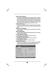
...Configuration ACPI Configuration Storage Configuration PCIPnP Configuration Floppy Configuration SuperIO Configuration USB Configuration BIOS Update Utility ASRock Instant Flash Select Screen Select Item Enter Go to update your BIOS, and reboot your BIOS only in below sections may set the configurations for the following items: ... operating systems first like MS-DOS or Windows®. Setting wrong values in Flash ROM. ASRock Instant Flash ASRock Instant Flash is a BIOS flash utility embedded in this section, you execute ASRock Instant Flash utility, the utility will show the...
...Configuration ACPI Configuration Storage Configuration PCIPnP Configuration Floppy Configuration SuperIO Configuration USB Configuration BIOS Update Utility ASRock Instant Flash Select Screen Select Item Enter Go to update your BIOS, and reboot your BIOS only in below sections may set the configurations for the following items: ... operating systems first like MS-DOS or Windows®. Setting wrong values in Flash ROM. ASRock Instant Flash ASRock Instant Flash is a BIOS flash utility embedded in this section, you execute ASRock Instant Flash utility, the utility will show the...


