
User Manual
Page 2
...errors or omissions that may apply, see www.dtsc.ca.gov/hazardouswaste/perchlorate" ASRock Website: http://www.asrock.com 2 CALIFORNIA, USA ONLY The Lithium battery adopted on this motherboard contains Perchlorate, a toxic substance controlled in this manual are used only for backup... purpose, without written consent of ASRock Inc. Disclaimer: Specifications and information contained in Perchlorate Best Management Practices (...
...errors or omissions that may apply, see www.dtsc.ca.gov/hazardouswaste/perchlorate" ASRock Website: http://www.asrock.com 2 CALIFORNIA, USA ONLY The Lithium battery adopted on this motherboard contains Perchlorate, a toxic substance controlled in this manual are used only for backup... purpose, without written consent of ASRock Inc. Disclaimer: Specifications and information contained in Perchlorate Best Management Practices (...

User Manual
Page 3
... 34 2.15.2 Installing Windows® 7 / 7 64-bit / VistaTM / VistaTM 64-bit Without RAID Functions 35 2.16 Untied Overclocking Technology 36 3 Contents 1 . Introduction 5 1.1 Package Contents 5 1.2 Specifications 6 1.3 Motherboard Layout 11 1.4 I/O Panel 12 2 .
... 34 2.15.2 Installing Windows® 7 / 7 64-bit / VistaTM / VistaTM 64-bit Without RAID Functions 35 2.16 Untied Overclocking Technology 36 3 Contents 1 . Introduction 5 1.1 Package Contents 5 1.2 Specifications 6 1.3 Motherboard Layout 11 1.4 I/O Panel 12 2 .

User Manual
Page 5
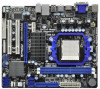
... to the hardware installation. www.asrock.com/support/index.asp 1.1 Package Contents ASRock 880GMH-LE/USB3 Motherboard (Micro ATX Form Factor: 9.6-in x 8.2-in, 24.4 cm x 20.8 cm) ASRock 880GMH-LE/USB3 Quick Installation Guide ASRock 880GMH-LE/USB3 Support CD 2 x Serial ATA (SATA) Data Cables (Optional) 1 x I/O Panel Shield 5 In this motherboard, please visit our website for purchasing ASRock 880GMH-LE/USB3 motherboard, a reliable motherboard produced under ASRock's consistently stringent quality control. 1. Introduction...
... to the hardware installation. www.asrock.com/support/index.asp 1.1 Package Contents ASRock 880GMH-LE/USB3 Motherboard (Micro ATX Form Factor: 9.6-in x 8.2-in, 24.4 cm x 20.8 cm) ASRock 880GMH-LE/USB3 Quick Installation Guide ASRock 880GMH-LE/USB3 Support CD 2 x Serial ATA (SATA) Data Cables (Optional) 1 x I/O Panel Shield 5 In this motherboard, please visit our website for purchasing ASRock 880GMH-LE/USB3 motherboard, a reliable motherboard produced under ASRock's consistently stringent quality control. 1. Introduction...

User Manual
Page 9
... file system. 9 Please visit our website for the operation procedures of memory modules on this motherboard, please refer to SATAII connector directly. 7. This convenient BIOS update tool allows you adopt. Due to read the installation guide of ASRock OC Tuner. It is a revolutionary technology that the USB flash drive or hard drive...
... file system. 9 Please visit our website for the operation procedures of memory modules on this motherboard, please refer to SATAII connector directly. 7. This convenient BIOS update tool allows you adopt. Due to read the installation guide of ASRock OC Tuner. It is a revolutionary technology that the USB flash drive or hard drive...

User Manual
Page 10
... . For EuP ready power supply selection, we recommend you resume the system, please check if the CPU fan on the same motherboard. 11. Please be shared and worked on the motherboard functions properly and unplug the power cord, then plug it is detected, the system will automatically shutdown. According to Intel's suggestion..., stands for the completed system. 10. While CPU overheat is not recommended to define the power consumption for Energy Using Product, was a provision regulated by ASRock, provides a convenient way for more details. 10
... . For EuP ready power supply selection, we recommend you resume the system, please check if the CPU fan on the same motherboard. 11. Please be shared and worked on the motherboard functions properly and unplug the power cord, then plug it is detected, the system will automatically shutdown. According to Intel's suggestion..., stands for the completed system. 10. While CPU overheat is not recommended to define the power consumption for Energy Using Product, was a provision regulated by ASRock, provides a convenient way for more details. 10
User Manual
Page 11
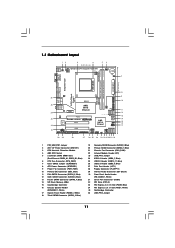
Blue) 34 PCI Express 2.0 x1 Slot (PCIE1; White) 35 Northbridge Controller 36 USB_PW2 Jumper 11 1.3 Motherboard Layout PS2 Mouse PS2 Keyboard 12 3 4 20.8cm (8.2-in) 56 1 PS2_USB_PW1 Hybrid CrossFire Support 6-Core CPU ATX12V1 CPU_FAN1 CMOS BATTERY HT3.0 ... B: USB1 Top: RJ-45 DX10.1 PWR_FAN1 Top: LINE IN Center: FRONT Bottom: MIC IN AMD 880G IDE1 Chipset LAN PCIE1 AUDIO CODEC Super I/O PCIE2 880GMH-LE/USB3 PCI1 1 HD_AUDIO1 1 COM1 CD1 FLOPPY1 PCI2 LPT1 1 SATAII_4 SATAII_5 SATAII_6 AMD SB710 Chipset RoHS 8Mb BIOS SPEAKER1 1 PANEL 1 PLED PWRBTN 1 HDLED RESET USB8_9...
Blue) 34 PCI Express 2.0 x1 Slot (PCIE1; White) 35 Northbridge Controller 36 USB_PW2 Jumper 11 1.3 Motherboard Layout PS2 Mouse PS2 Keyboard 12 3 4 20.8cm (8.2-in) 56 1 PS2_USB_PW1 Hybrid CrossFire Support 6-Core CPU ATX12V1 CPU_FAN1 CMOS BATTERY HT3.0 ... B: USB1 Top: RJ-45 DX10.1 PWR_FAN1 Top: LINE IN Center: FRONT Bottom: MIC IN AMD 880G IDE1 Chipset LAN PCIE1 AUDIO CODEC Super I/O PCIE2 880GMH-LE/USB3 PCI1 1 HD_AUDIO1 1 COM1 CD1 FLOPPY1 PCI2 LPT1 1 SATAII_4 SATAII_5 SATAII_6 AMD SB710 Chipset RoHS 8Mb BIOS SPEAKER1 1 PANEL 1 PLED PWRBTN 1 HDLED RESET USB8_9...

User Manual
Page 13
... do not over-tighten the screws! Doing so may cause severe damage to do not touch the ICs. 4. Pre-installation Precautions Take note of your motherboard directly on a grounded antistatic pad or in the bag that the power is switched off or the power cord is a Micro ATX Form Factor (9.6-in... x 8.2-in, 24.4 cm x 20.8 cm) motherboard. Unplug the power cord from the power supply. When placing screws into it on the carpet or the like. 2. Installation This is detached from the...
... do not over-tighten the screws! Doing so may cause severe damage to do not touch the ICs. 4. Pre-installation Precautions Take note of your motherboard directly on a grounded antistatic pad or in the bag that the power is switched off or the power cord is a Micro ATX Form Factor (9.6-in... x 8.2-in, 24.4 cm x 20.8 cm) motherboard. Unplug the power cord from the power supply. When placing screws into it on the carpet or the like. 2. Installation This is detached from the...

User Manual
Page 14
... socket lever to the CPU FAN connector (CPU_FAN1, see Page 11, No. 6). The lever clicks on the socket while you install the CPU into this motherboard, it is locked. Make sure that the CPU corner with the golden triangle matches the socket corner with each other. Unlock the socket by lifting...
... socket lever to the CPU FAN connector (CPU_FAN1, see Page 11, No. 6). The lever clicks on the socket while you install the CPU into this motherboard, it is locked. Make sure that the CPU corner with the golden triangle matches the socket corner with each other. Unlock the socket by lifting...

User Manual
Page 15
... clips at incorrect orientation. Step 3. If you install only one correct orientation. Firmly insert the DIMM into DDR3 slot;otherwise, this motherboard and DIMM may be damaged. 2. Unlock a DIMM slot by pressing the retaining clips outward. It will operate at single channel mode...non-identical memory modules, it is not allowed to activate the Dual Channel Memory Technology. 2.3 Installation of Memory Modules (DIMM) 880GMH-LE/USB3 motherboard provides two 240-pin DDR3 (Double Data Rate 3) DIMM slots, and supports Dual Channel Memory Technology. notch break notch break ...
... clips at incorrect orientation. Step 3. If you install only one correct orientation. Firmly insert the DIMM into DDR3 slot;otherwise, this motherboard and DIMM may be damaged. 2. Unlock a DIMM slot by pressing the retaining clips outward. It will operate at single channel mode...non-identical memory modules, it is not allowed to activate the Dual Channel Memory Technology. 2.3 Installation of Memory Modules (DIMM) 880GMH-LE/USB3 motherboard provides two 240-pin DDR3 (Double Data Rate 3) DIMM slots, and supports Dual Channel Memory Technology. notch break notch break ...

User Manual
Page 16
...: PCIE1 (PCIE x1 slot; White) is used for PCI Express cards with the slot and press firmly until the card is completely seated on this motherboard. PCIE2 (PCIE x16 slot; Please read the documentation of the expansion card and make sure that have the 32-bit PCI interface. Fasten the card... is already installed in a chassis). Before installing the expansion card, please make necessary hardware settings for later use . Remove the system unit cover (if your motherboard is unplugged. Step 4. Step 5.
...: PCIE1 (PCIE x1 slot; White) is used for PCI Express cards with the slot and press firmly until the card is completely seated on this motherboard. PCIE2 (PCIE x16 slot; Please read the documentation of the expansion card and make sure that have the 32-bit PCI interface. Fasten the card... is already installed in a chassis). Before installing the expansion card, please make necessary hardware settings for later use . Remove the system unit cover (if your motherboard is unplugged. Step 4. Step 5.

User Manual
Page 17
... other one will be disabled. 2. When one of dual monitor feature without installing any add-on VGA card to use dual monitor function on this motherboard. With the internal VGA output support (DVI-D, D-Sub and HDMI), you playback HDCP-protected video from Blu-ray (BD) or HD-DVD disc, ... content will be displayed only in one of the two monitors instead of dual monitor function after your computer. When you can start to this motherboard. 1. If you can drive same or different display contents. If you have installed onboard VGA driver from our support CD to your system already,...
... other one will be disabled. 2. When one of dual monitor feature without installing any add-on VGA card to use dual monitor function on this motherboard. With the internal VGA output support (DVI-D, D-Sub and HDMI), you playback HDCP-protected video from Blu-ray (BD) or HD-DVD disc, ... content will be displayed only in one of the two monitors instead of dual monitor function after your computer. When you can start to this motherboard. 1. If you can drive same or different display contents. If you have installed onboard VGA driver from our support CD to your system already,...

User Manual
Page 18
... E. F. Click "Apply" or "OK" to page 16 for proper expansion card installation procedures for the second monitor. Surround Display Feature This motherboard supports surround display upgrade. Boot your primary monitor, and then select "Primary". When you use multiple monitors with your system. D. Right-click ... Express VGA card on PCI Express VGA card driver to HDMI port on each monitor. G. Click "Extend my Windows desktop onto this motherboard. 4. If you wish to this monitor". Set the "Screen Resolution" and "Color Quality" as Secondary. Install the ATITM PCI Express...
... E. F. Click "Apply" or "OK" to page 16 for proper expansion card installation procedures for the second monitor. Surround Display Feature This motherboard supports surround display upgrade. Boot your primary monitor, and then select "Primary". When you use multiple monitors with your system. D. Right-click ... Express VGA card on PCI Express VGA card driver to HDMI port on each monitor. G. Click "Extend my Windows desktop onto this motherboard. 4. If you wish to this monitor". Set the "Screen Resolution" and "Color Quality" as Secondary. Install the ATITM PCI Express...

User Manual
Page 19
...the display icons to below . Please refer to positions representing the physical setup of your change. Due to use HDCP function with this motherboard, you can adjust the parameters of content as well. B. D. The placement of intercepting digital data midstream between the video source, or... by the number three and four. 6. A. Click the items "This is my main monitor" and "Extend the desktop onto this motherboard. What is a copy protection scheme to eliminate the possibility of display icons determines how you would like to the increase in manufacturers employing...
...the display icons to below . Please refer to positions representing the physical setup of your change. Due to use HDCP function with this motherboard, you can adjust the parameters of content as well. B. D. The placement of intercepting digital data midstream between the video source, or... by the number three and four. 6. A. Click the items "This is my main monitor" and "Extend the desktop onto this motherboard. What is a copy protection scheme to eliminate the possibility of display icons determines how you would like to the increase in manufacturers employing...

User Manual
Page 20
... in a Windows® VistaTM / 7 environment. An ATITM Hybrid CrossFireXTM system includes an ATITM RadeonTM 5450 series graphics processor and a motherboard based on PCIE2 slot. For the future update of ATITM Hybrid CrossFireXTM Step 1. Step 2. Enter "Advanced" screen, and enter "Chipset... XP OS. Install one compatible PCI Express graphics card to [Enabled]. Step 6. 2.6 ATITM Hybrid CrossFireXTM Operation Guide This motherboard supports ATITM Hybrid CrossFireXTM feature. Restart your computer. What does an ATITM Hybrid CrossFireXTM system include? Vendor Chipset ATI RADEON ...
... in a Windows® VistaTM / 7 environment. An ATITM Hybrid CrossFireXTM system includes an ATITM RadeonTM 5450 series graphics processor and a motherboard based on PCIE2 slot. For the future update of ATITM Hybrid CrossFireXTM Step 1. Step 2. Enter "Advanced" screen, and enter "Chipset... XP OS. Install one compatible PCI Express graphics card to [Enabled]. Step 6. 2.6 ATITM Hybrid CrossFireXTM Operation Guide This motherboard supports ATITM Hybrid CrossFireXTM feature. Restart your computer. What does an ATITM Hybrid CrossFireXTM system include? Vendor Chipset ATI RADEON ...

User Manual
Page 23
... support SATAII or SATA hard disk for the details. Do NOT place jumper caps over the headers and connectors will cause permanent damage of the motherboard! • Floppy Connector (33-pin FLOPPY1) (see p.11 No. 28) Pin1 FLOPPY1 the red-striped side to Pin1 Note: Make sure the red-striped ... SATAII_4 SATAII_5 SATAII_6 (SATAII_5: see p.11, No. 11) (SATAII_6: see p.11 No. 10) PIN1 IDE1 connect the blue end connect the black end to the motherboard to the IDE devices 80-conductor ATA 66/100/133 cable Note: Please refer to the instruction of the SATA data cable can be connected...
... support SATAII or SATA hard disk for the details. Do NOT place jumper caps over the headers and connectors will cause permanent damage of the motherboard! • Floppy Connector (33-pin FLOPPY1) (see p.11 No. 28) Pin1 FLOPPY1 the red-striped side to Pin1 Note: Make sure the red-striped ... SATAII_4 SATAII_5 SATAII_6 (SATAII_5: see p.11, No. 11) (SATAII_6: see p.11 No. 10) PIN1 IDE1 connect the blue end connect the black end to the motherboard to the IDE devices 80-conductor ATA 66/100/133 cable Note: Please refer to the instruction of the SATA data cable can be connected...

User Manual
Page 24
.... 30) GND PRESENCE# MIC_RET OUT_RET 1 OUT2_L J_SENSE OUT2_R MIC2_R MIC2_L Besides five default USB 2.0 ports on the I/O panel, there are three USB 2.0 headers on this motherboard.
.... 30) GND PRESENCE# MIC_RET OUT_RET 1 OUT2_L J_SENSE OUT2_R MIC2_R MIC2_L Besides five default USB 2.0 ports on the I/O panel, there are three USB 2.0 headers on this motherboard.

User Manual
Page 25
... (RIN) to OUT2_R and Audio_L (LIN) to Ground (GND). Connect Ground (GND) to OUT2_L. Please connect the chassis speaker to this motherboard provides 4-Pin CPU fan (Quiet Fan) support, the 3-Pin CPU fan still can work successfully even without the fan speed control function. Chassis...pin PANEL1) (see p.11 No. 17) Chassis Speaker Header (4-pin SPEAKER 1) (see p.11 No. 6) 1 2 3 4 Please connect the CPU fan cable to this motherboard, please connect it to the CPU Fan Connector (4-pin CPU_FAN1) (see p.11 No. 16) PLED+ PLEDPWRBTN# GND 1 DUMMY RESET# GND HDLEDHDLED+ 1 SPEAKER DUMMY DUMMY +...
... (RIN) to OUT2_R and Audio_L (LIN) to Ground (GND). Connect Ground (GND) to OUT2_L. Please connect the chassis speaker to this motherboard provides 4-Pin CPU fan (Quiet Fan) support, the 3-Pin CPU fan still can work successfully even without the fan speed control function. Chassis...pin PANEL1) (see p.11 No. 17) Chassis Speaker Header (4-pin SPEAKER 1) (see p.11 No. 6) 1 2 3 4 Please connect the CPU fan cable to this motherboard, please connect it to the CPU Fan Connector (4-pin CPU_FAN1) (see p.11 No. 16) PLED+ PLEDPWRBTN# GND 1 DUMMY RESET# GND HDLEDHDLED+ 1 SPEAKER DUMMY DUMMY +...

User Manual
Page 26
... Power Connector (4-pin ATX12V1) (see p.11 No. 2) Serial port Header (9-pin COM1) (see p.11 No. 8) 12 24 Please connect an ATX power supply to this motherboard provides 24-pin ATX power connector, 12 24 it can still work if you adopt a traditional 20-pin ATX power supply.
... Power Connector (4-pin ATX12V1) (see p.11 No. 2) Serial port Header (9-pin COM1) (see p.11 No. 8) 12 24 Please connect an ATX power supply to this motherboard provides 24-pin ATX power connector, 12 24 it can still work if you adopt a traditional 20-pin ATX power supply.

User Manual
Page 28
...to use RAID 10 function, you to the SATA / SATAII hard disk. 2.10 Serial ATA (SATA) / Serial ATAII (SATAII) Hard Disks Installation This motherboard adopts AMD SB710 south bridge chipset that supports Serial ATA (SATA) / Serial ATAII (SATAII) hard disks and RAID (RAID 0, RAID 1, RAID 10 and JBOD... SATAII hard disks. This section will guide you need to the SATA / SATAII hard disk. You may install SATA / SATAII hard disks on this motherboard for internal storage devices. STEP 3: Connect one end of your chassis. STEP 1: Install the SATA / SATAII hard disks into the drive bays of...
...to use RAID 10 function, you to the SATA / SATAII hard disk. 2.10 Serial ATA (SATA) / Serial ATAII (SATAII) Hard Disks Installation This motherboard adopts AMD SB710 south bridge chipset that supports Serial ATA (SATA) / Serial ATAII (SATAII) hard disks and RAID (RAID 0, RAID 1, RAID 10 and JBOD... SATAII hard disks. This section will guide you need to the SATA / SATAII hard disk. You may install SATA / SATAII hard disks on this motherboard for internal storage devices. STEP 3: Connect one end of your chassis. STEP 1: Install the SATA / SATAII hard disks into the drive bays of...

User Manual
Page 29
... / SATAII HDDs while the system is still power-on and in working condition. 2.11 Hot Plug and Hot Swap Functions for SATA / SATAII HDDs This motherboard supports Hot Plug and Hot Swap functions for SATA host controllers developed thru a joint industry effort. What is Hot Plug Function? NOTE What is Hot...
... / SATAII HDDs while the system is still power-on and in working condition. 2.11 Hot Plug and Hot Swap Functions for SATA / SATAII HDDs This motherboard supports Hot Plug and Hot Swap functions for SATA host controllers developed thru a joint industry effort. What is Hot Plug Function? NOTE What is Hot...

